


Skymaster 1:7.5 F-4 Phantom

 02-08-2023, 10:06 AM
#527

My Feedback: (1)

Thanks Kevin. It wasn't without struggle but we got it done. Spent about 1 hour on the first wing getting the hard wire through to pull the wire through. My buddy who usually comes over on Saturday afternoons to help/learn was helping with the first wing. We finally got the wire through and then he pulled it out by accident! NOOOOOO. Second wing went quicker but both were easier than the vertical stab.

The following 2 users liked this post by yeahbaby:
Canadian Man (02-08-2023),
Malcolm H (02-08-2023)
02-15-2023, 09:01 AM
#531
My Feedback: (1)
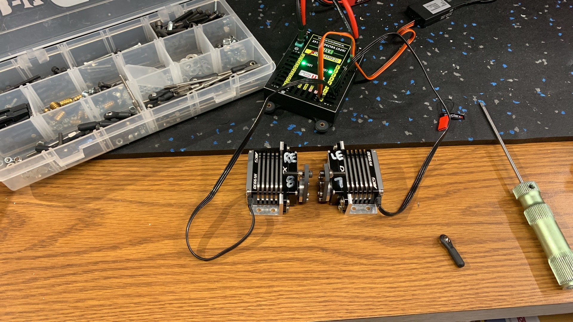
Wings finished up on both aircraft. New one gets tip lights and made up lenses with coloured West Systems epoxy.
Installed
Covers installed and linkages painted
New Rudder doesn't have blind nut exposed. There ended up being one but just needed to find it and cut out skin to expose.
02-15-2023, 09:05 AM
#532
My Feedback: (1)
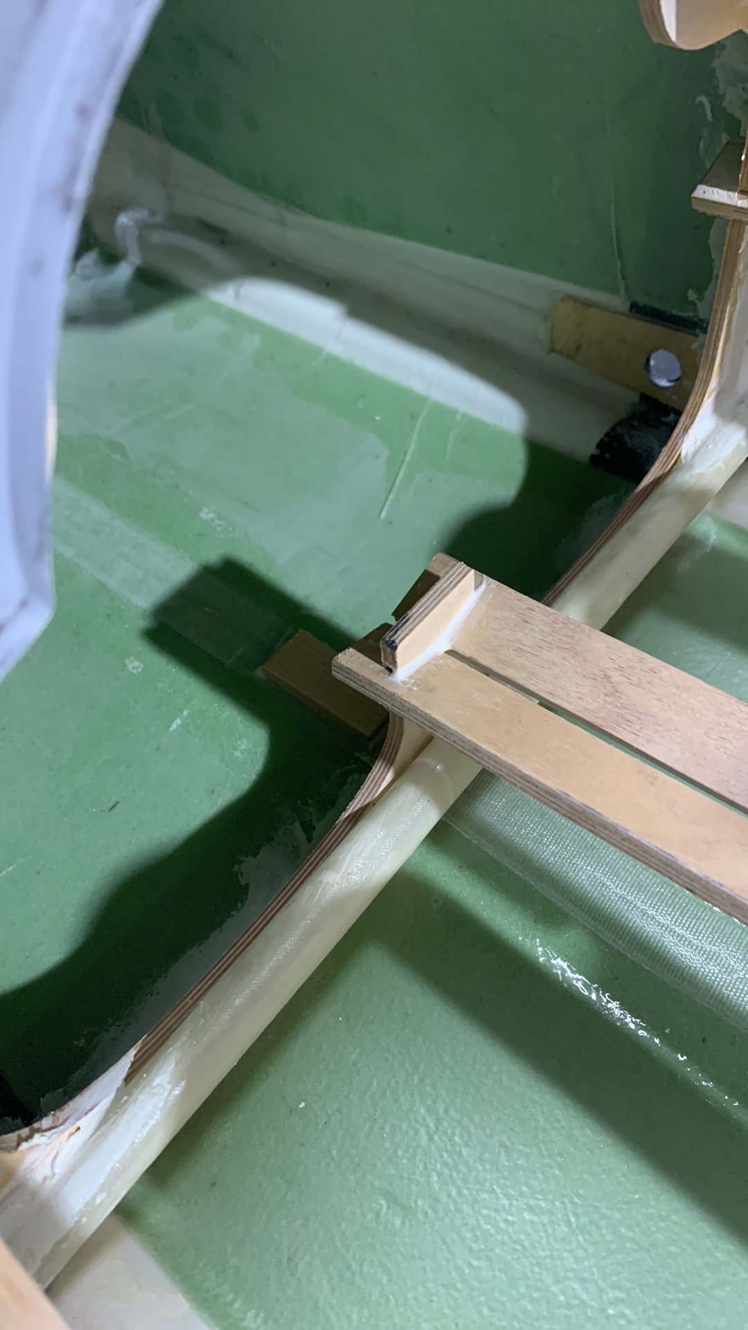
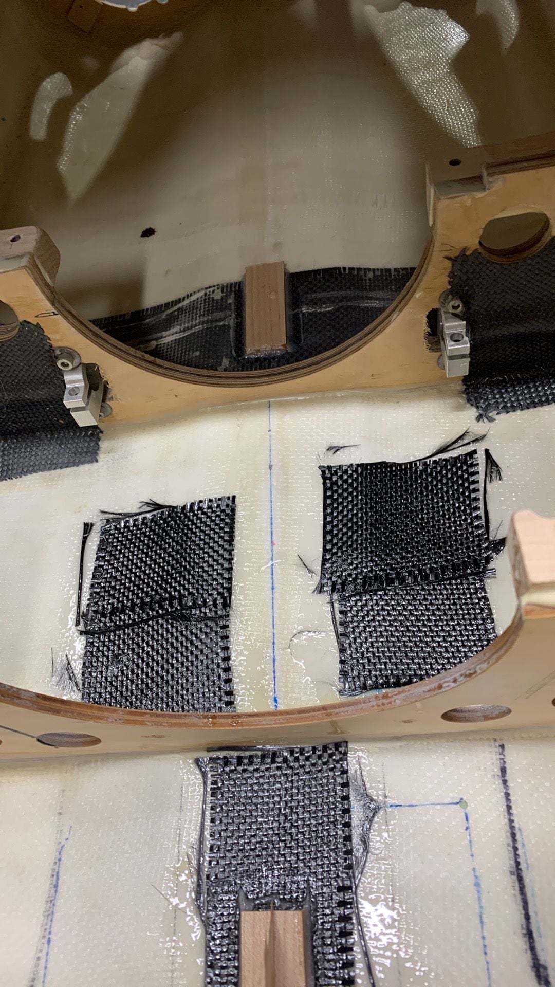
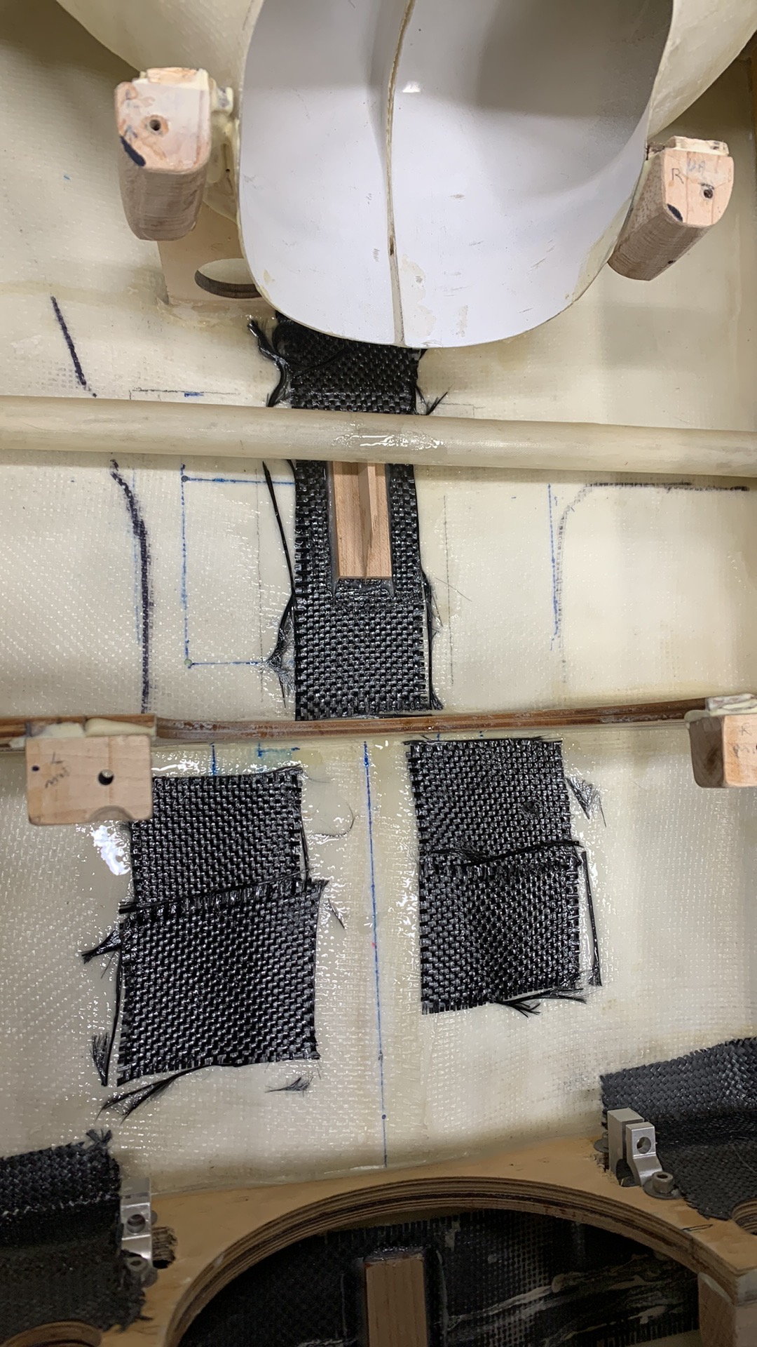
Center tank maple block glued in place behind engine mount formers. Cant see in the picture but I glued a piece of carbon onto the center section of engine rails. This is because I drilled a hole through this area to pass the tail section wires through. Needed reinforcement.
Front of new aircraft. Long strip of maple 1/4" wood installed. Adds support for fuel tanks.
Rudder hinging.
Old aircraft. Maple blocks added for center tank.
New Aircraft center tank installed.
Used keyholes for center tank.
Old aircraft center tank mounted.
02-15-2023, 09:11 AM
#533
My Feedback: (1)
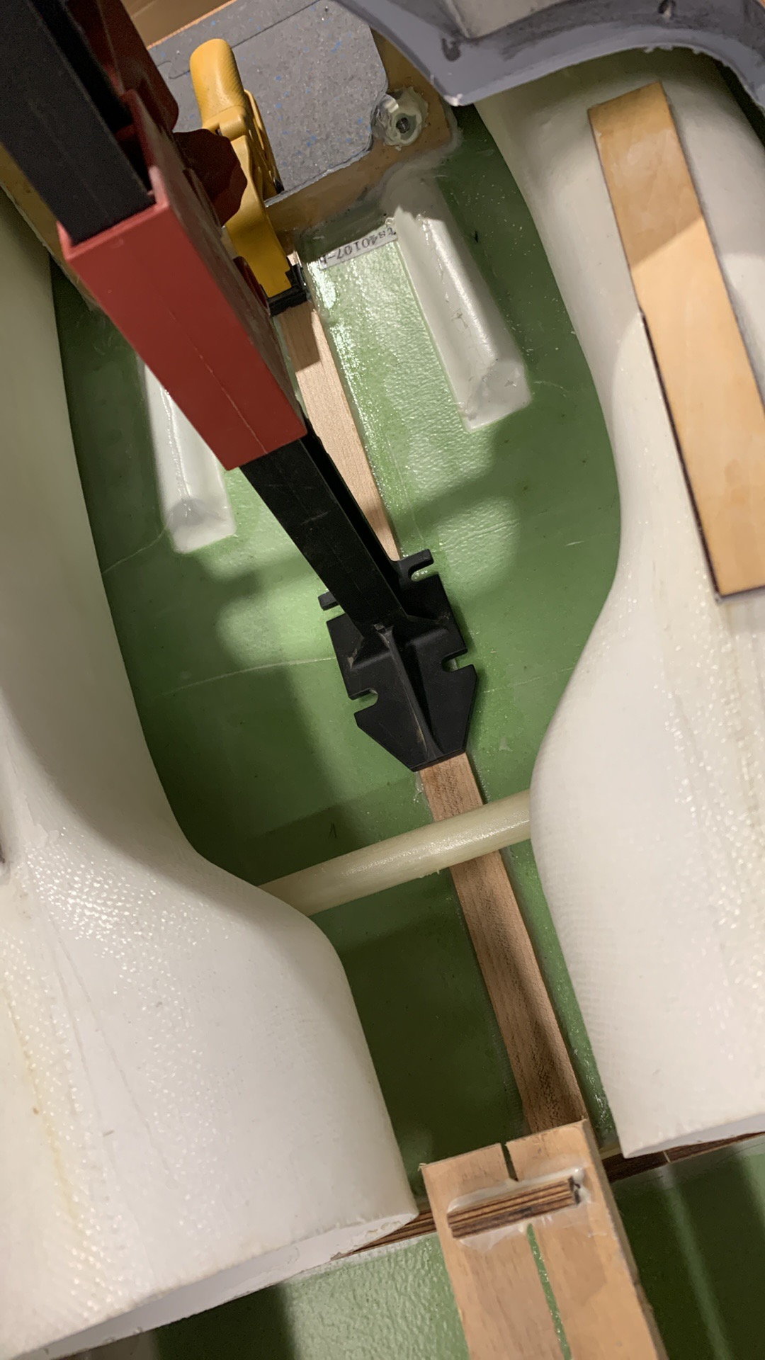
Rudder Setup on old aircraft. Not ideal, as i prefer clevis' but due to holes through former and odd angles balls were needed on one side and clevis on the other side.
New aircraft. Perfect setup!
Hole added to rudder for rear facing light.
Vertical stab leading edge light cutout. The lights we used here are 2 separate units. Perfect.
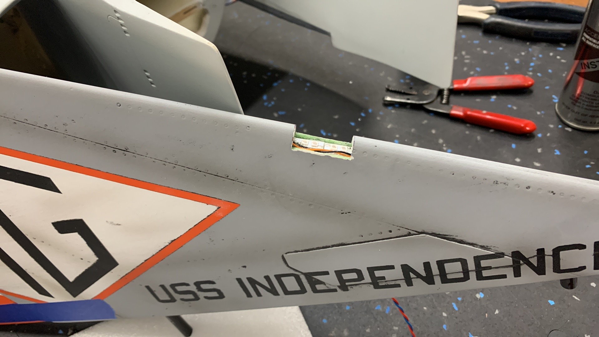
Added included heat shrink and then lights on top. CA used to glue it all in place.
Location of Rudder light wires.
Rudder leading edge lens complete.
Working on elevators on old aircraft.
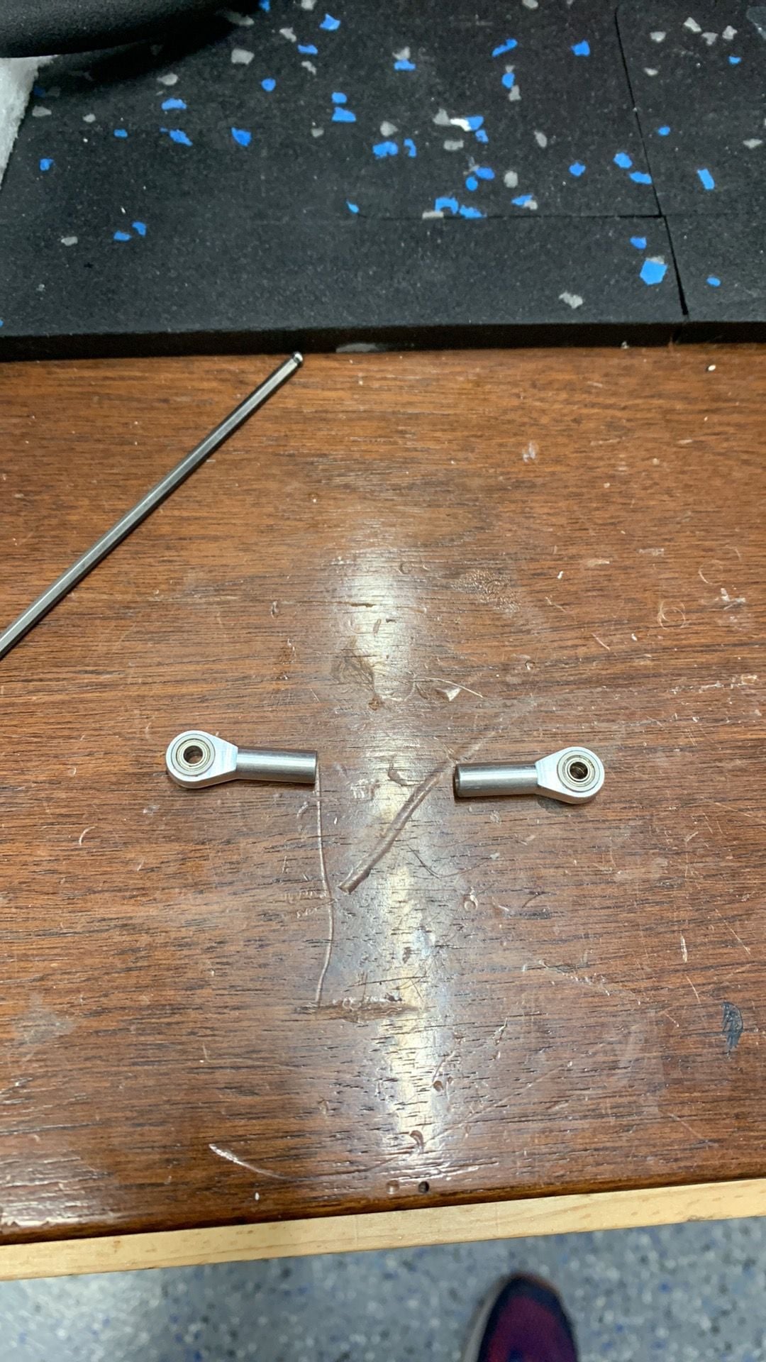
Hardware included with old kit. Not using as no side to side movement availiable.
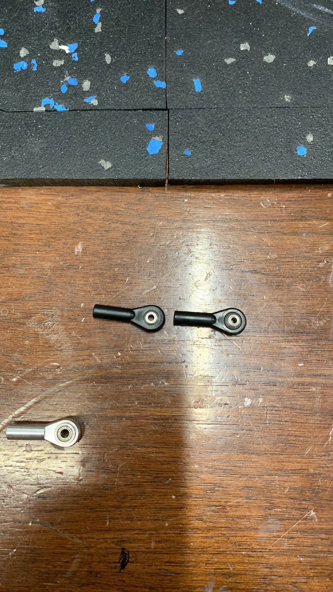
elevator hardware included with new kit. Not using as it uses 2mm hardware to go through balls and elevator horns are 2.5mm or 3mm hardware.
02-15-2023, 09:15 AM
#534
My Feedback: (1)
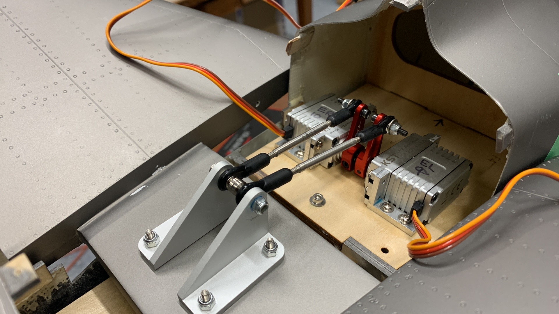
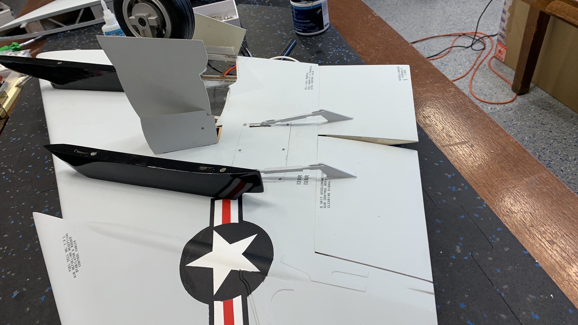
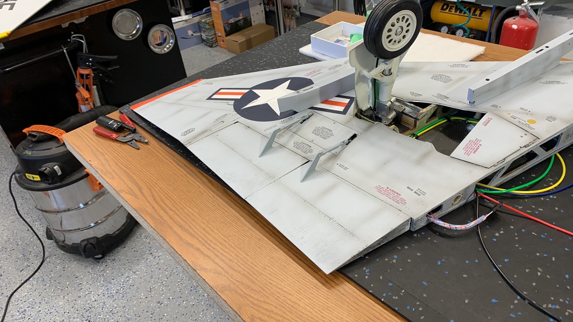
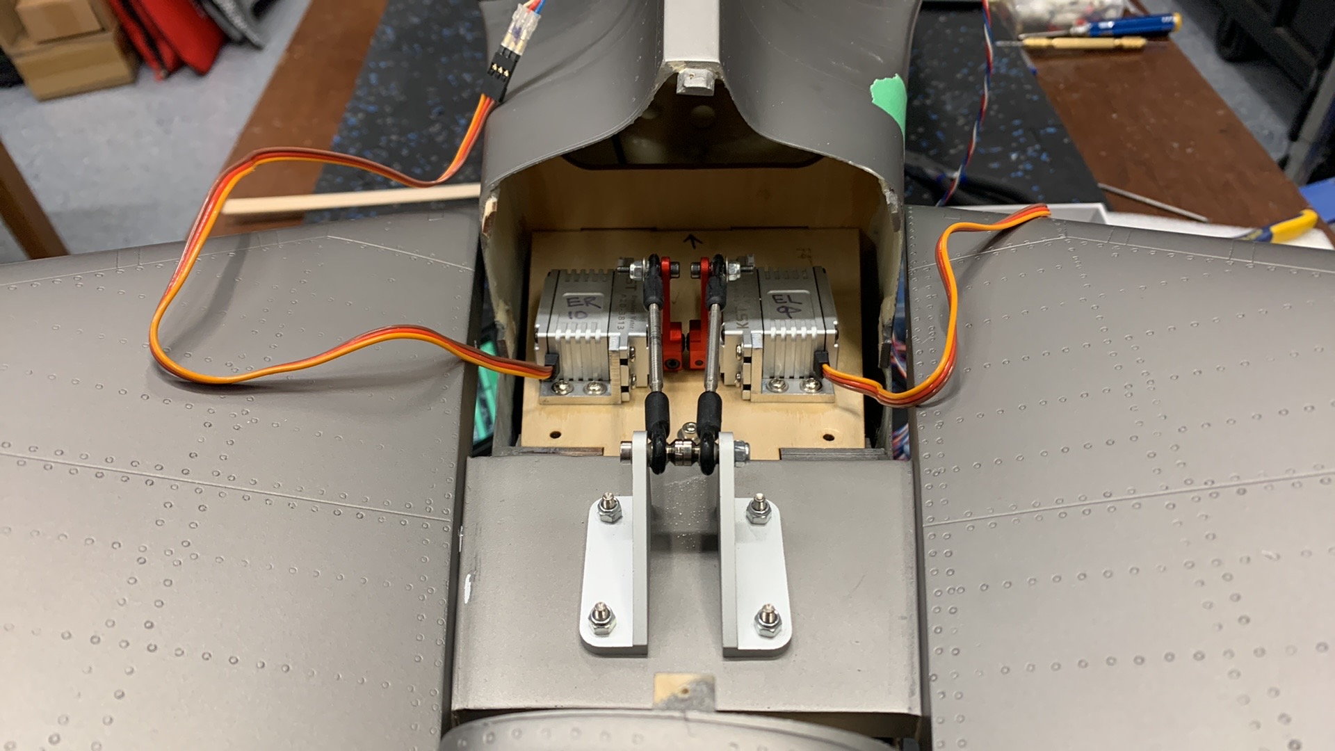
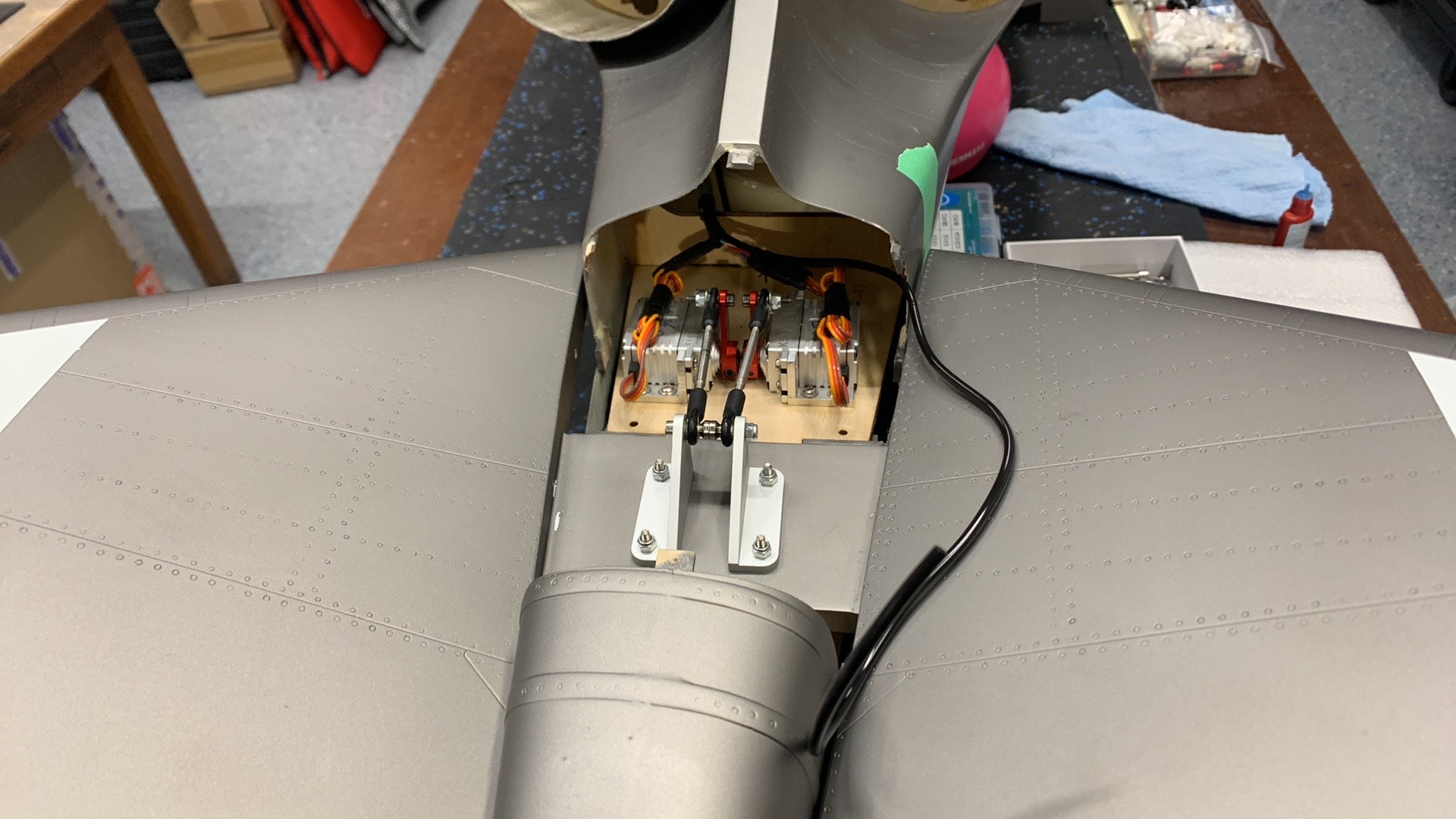
OLD Aircraft Elevator setup. NOTE! I ended up moving the surface mounted ball joints as this area needs to be kept clear for Tail Chute Pushrod to come through.
New kit has much more of the elevator cutout removed compared to old it.
New kit elevator setup.
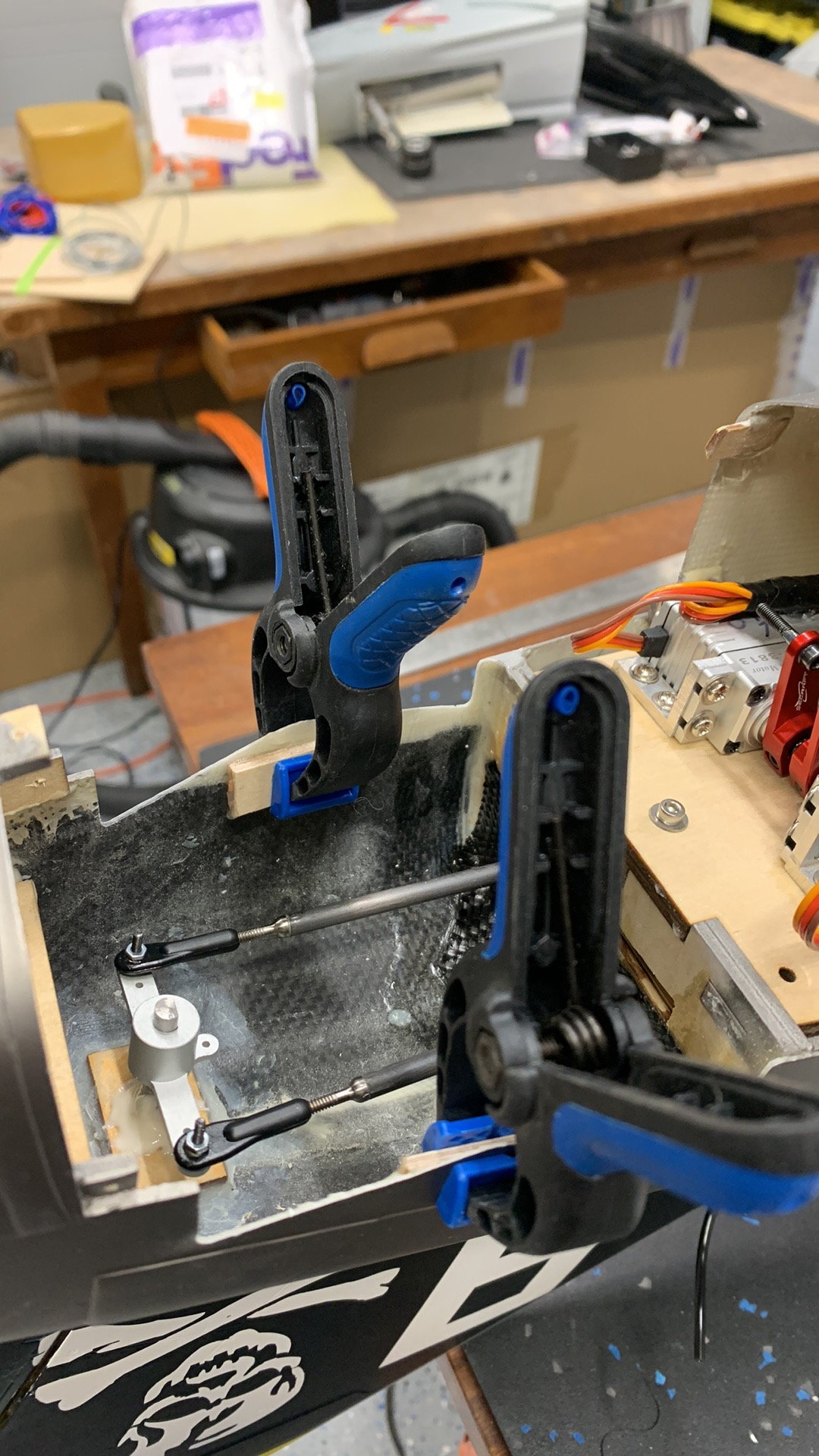
Adding backer for elevator covers to screw into.
Working on Turkey feather mounting on new kit.
Old kit, turkey feathers were already sorted by the pevious owner.
02-15-2023, 09:18 AM
#535
My Feedback: (1)
New Turkey feathers
Old turkey feathers
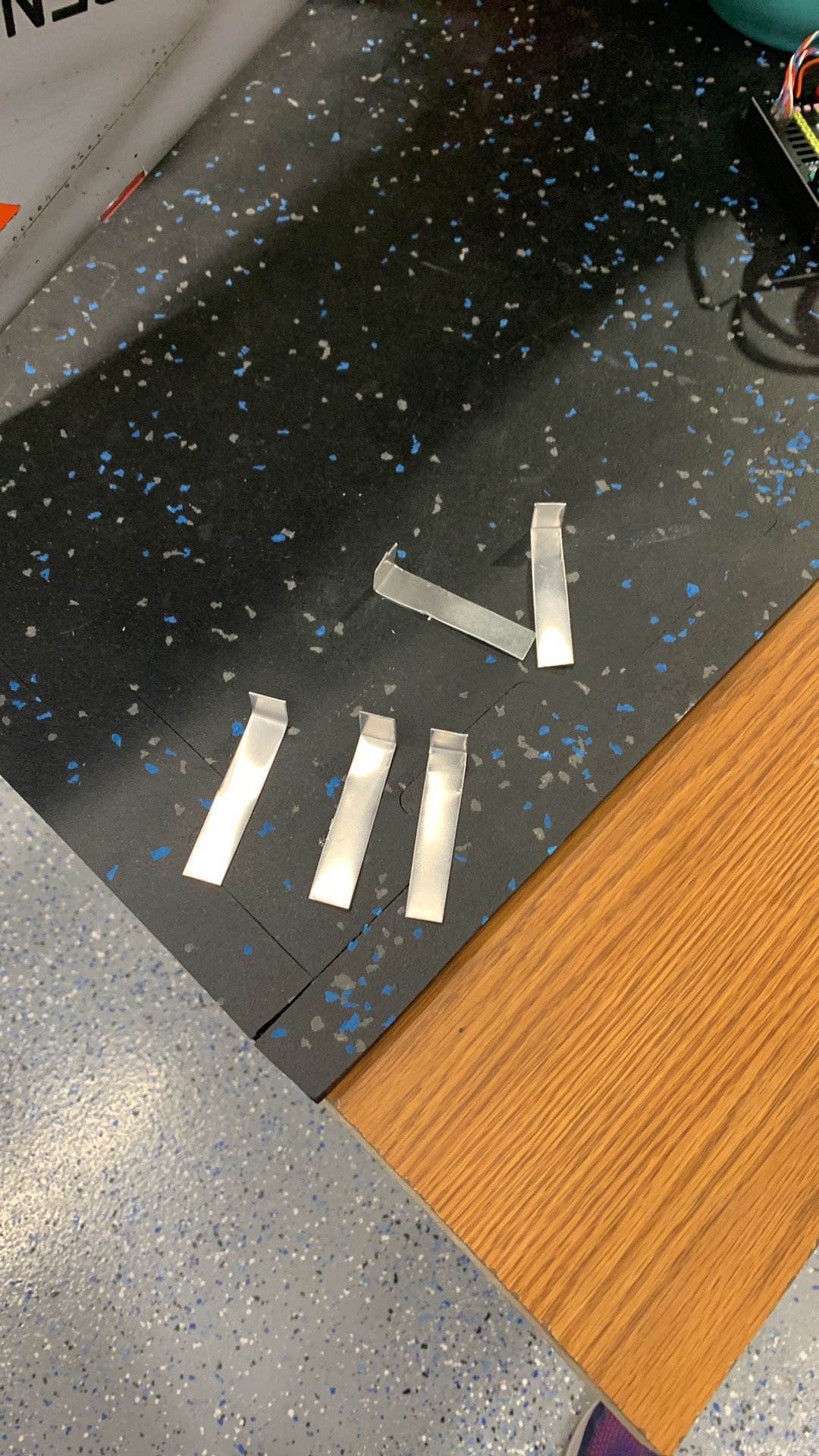
Aluminum straps for mounting.
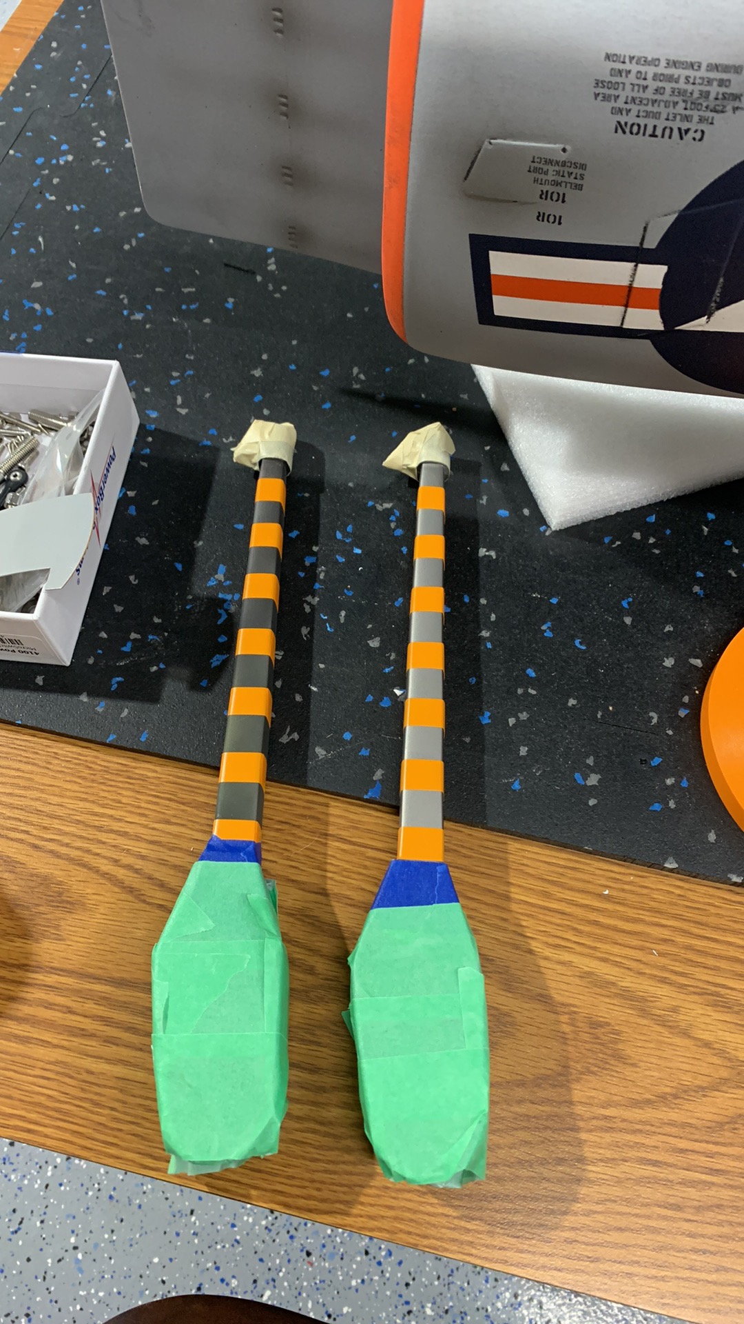
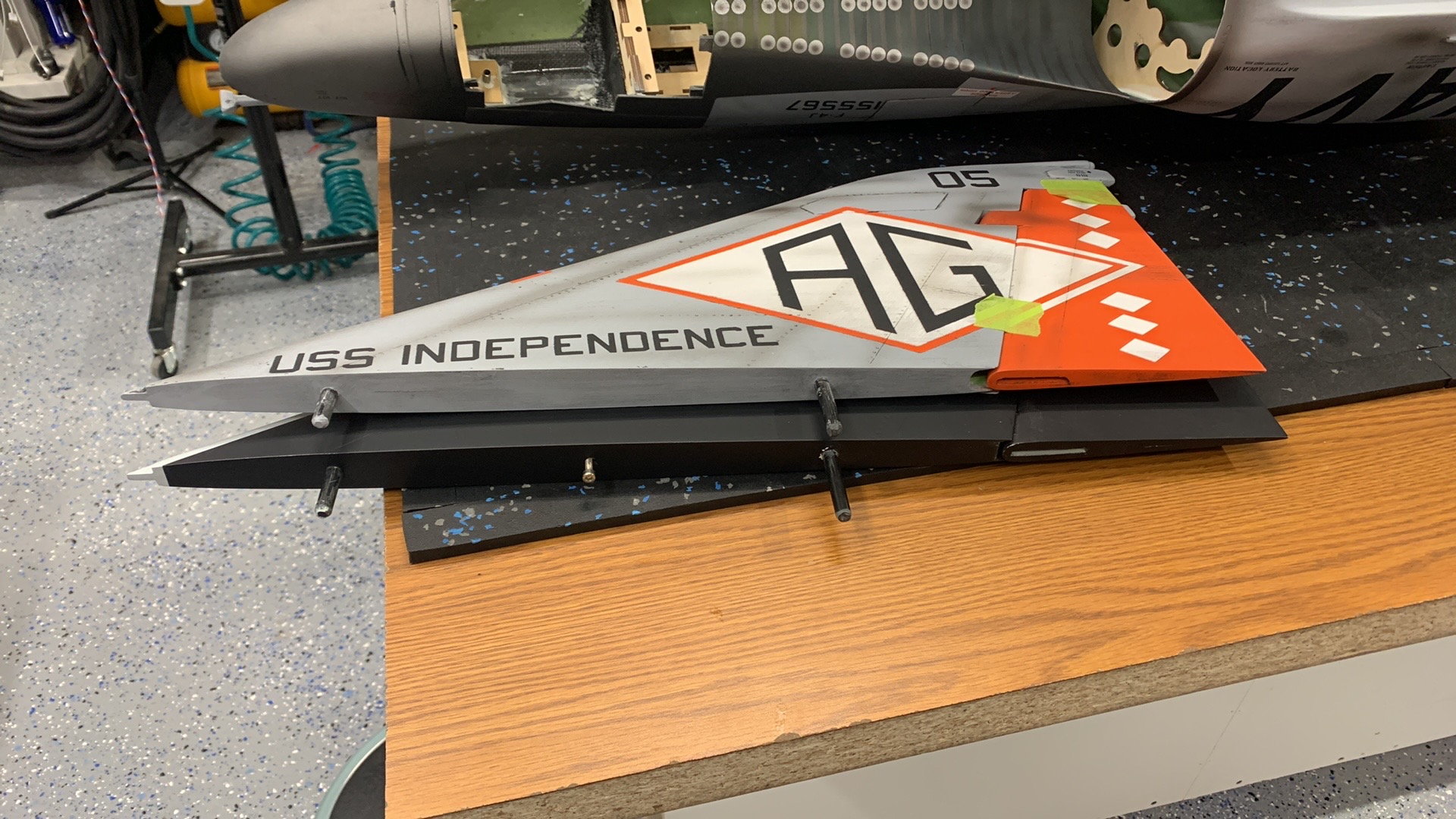
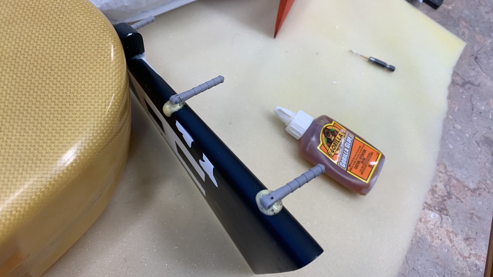
Tail hooks prepped off for paint.
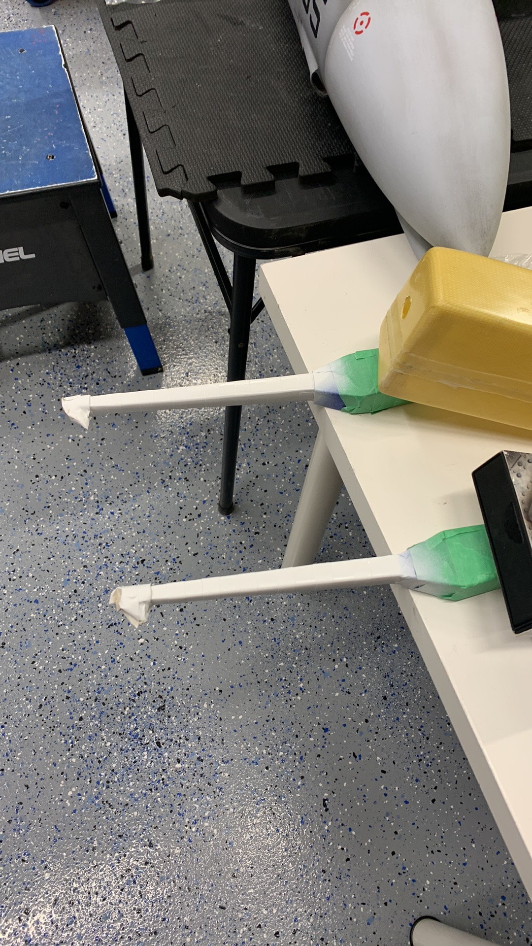
Painted
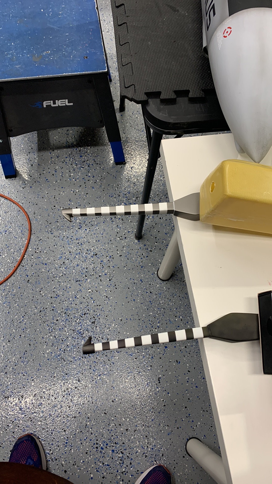
Final Result. Tail hooks will be screwed on. Need to be removable for access to tail section hatch. Tail hooks will not be functional.
 02-21-2023, 05:51 PM
#537
Join Date: May 2018
Posts: 3
Likes: 0
Received 0 Likes
on
0 Posts
I know it�s in this thread but for the life of me I can�t find it. I�m installing a Kigtech 210 with a larger stock y tailpipe with the bent up tail section. I know people are saying flip the pipe so they are facing more downward. Question is how much and how. Do you zero the turbine on the mounts with shims and then run the flipped tailpipe more or less centered in the exhaust nozzle portion? Do you keep the 5 degree downward tail section of the turbine plus flipping the pipe so that it�s even more downward like approximately 10-12 degrees downward? If anybody has done this install on a single 180 plus turbine and stock pipe can you post how you did it and how it flew? I was going to use the stock rails at 5 degrees and center the inverted y pipe or maybe slightly toward the top so they aren�t heating up the exhaust nozzles.
thanx!
thanx!
02-22-2023, 06:14 AM
#538
My Feedback: (1)
I know it’s in this thread but for the life of me I can’t find it. I’m installing a Kigtech 210 with a larger stock y tailpipe with the bent up tail section. I know people are saying flip the pipe so they are facing more downward. Question is how much and how. Do you zero the turbine on the mounts with shims and then run the flipped tailpipe more or less centered in the exhaust nozzle portion? Do you keep the 5 degree downward tail section of the turbine plus flipping the pipe so that it’s even more downward like approximately 10-12 degrees downward? If anybody has done this install on a single 180 plus turbine and stock pipe can you post how you did it and how it flew? I was going to use the stock rails at 5 degrees and center the inverted y pipe or maybe slightly toward the top so they aren’t heating up the exhaust nozzles.
thanx!
thanx!
02-22-2023, 07:54 AM
#539
Join Date: May 2018
Posts: 3
Likes: 0
Received 0 Likes
on
0 Posts
Ok so you want to have 0 degrees on the turbine mount and invert the tailpipe and try to get that to 5 degrees? With the stock mounts they are at 5 degrees downward angle so I need to change that or the inverted tailpipe will have way more than 5. Bottom line it seems you need 5 degrees downward on the tailpipe end where it exits. So
02-22-2023, 08:30 AM
#540
My Feedback: (1)
Ok so you want to have 0 degrees on the turbine mount and invert the tailpipe and try to get that to 5 degrees? With the stock mounts they are at 5 degrees downward angle so I need to change that or the inverted tailpipe will have way more than 5. Bottom line it seems you need 5 degrees downward on the tailpipe end where it exits. So
I built one with Tam pipe straight and one with stock pipe turned upside down
Last edited by kevinthoele; 02-22-2023 at 08:32 AM.
02-22-2023, 09:02 AM
#543
My Feedback: (1)
huge photo drop from the last 2 videos.
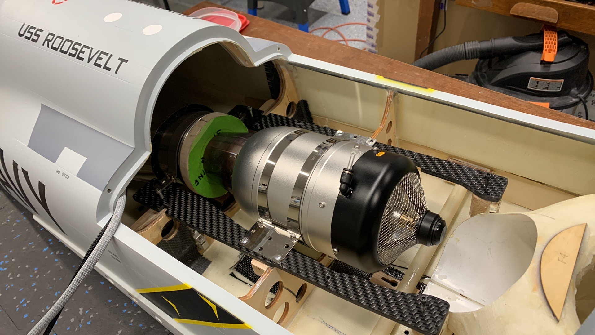
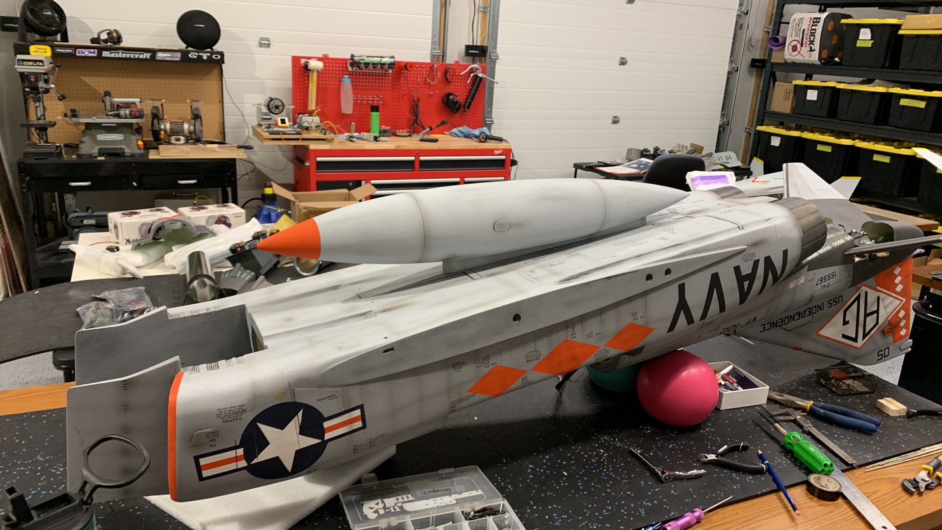
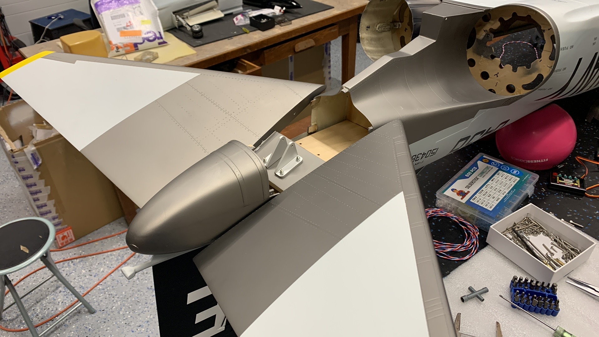
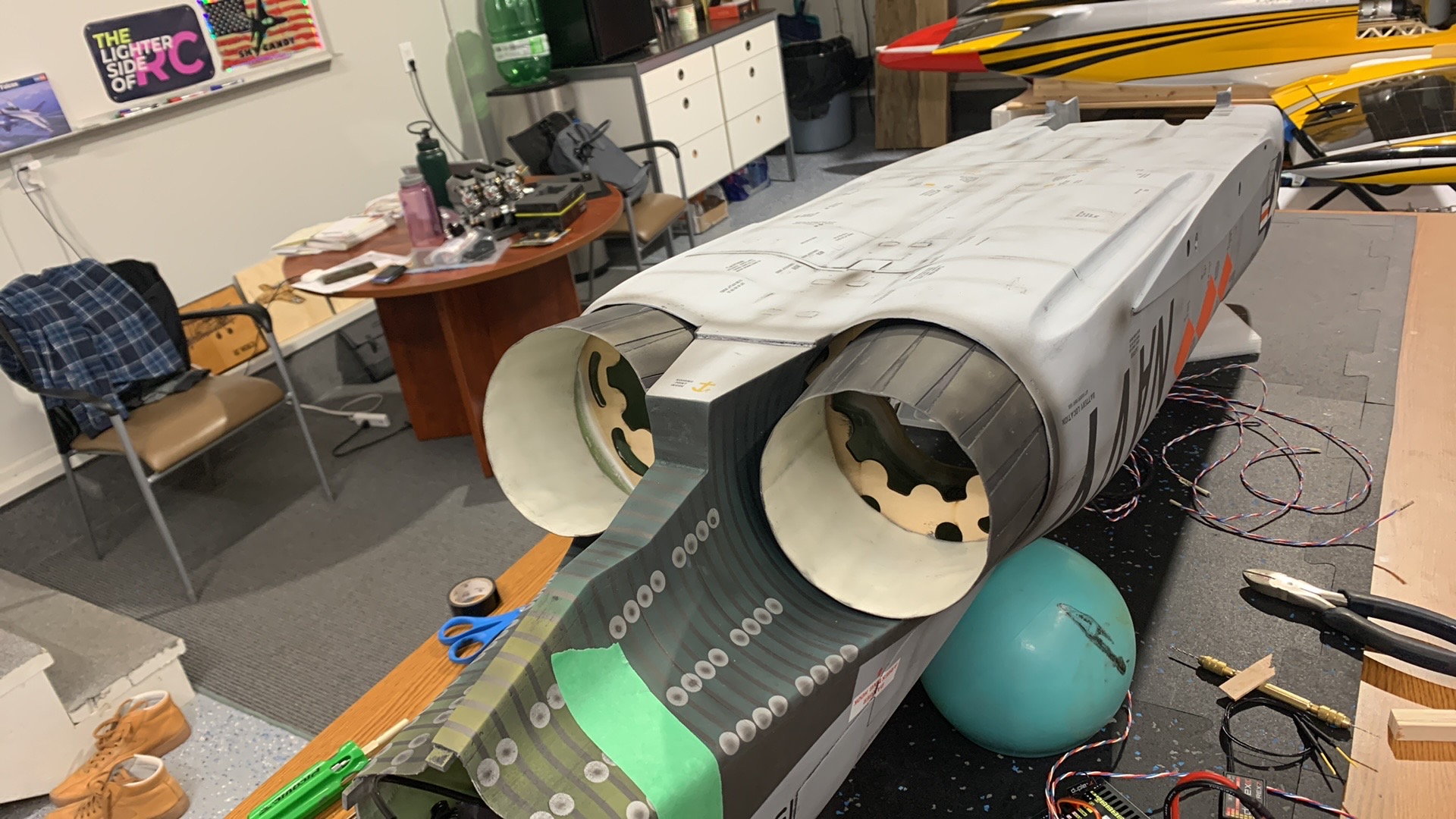
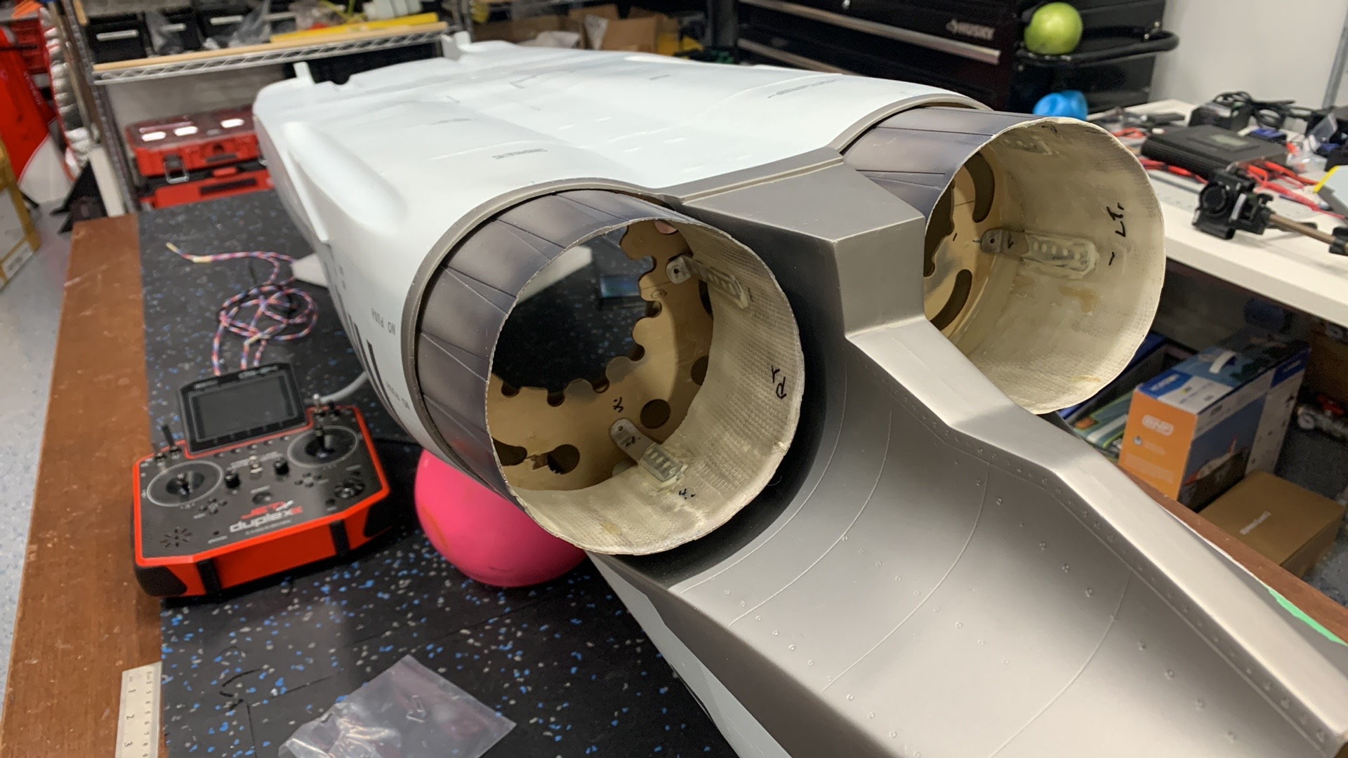
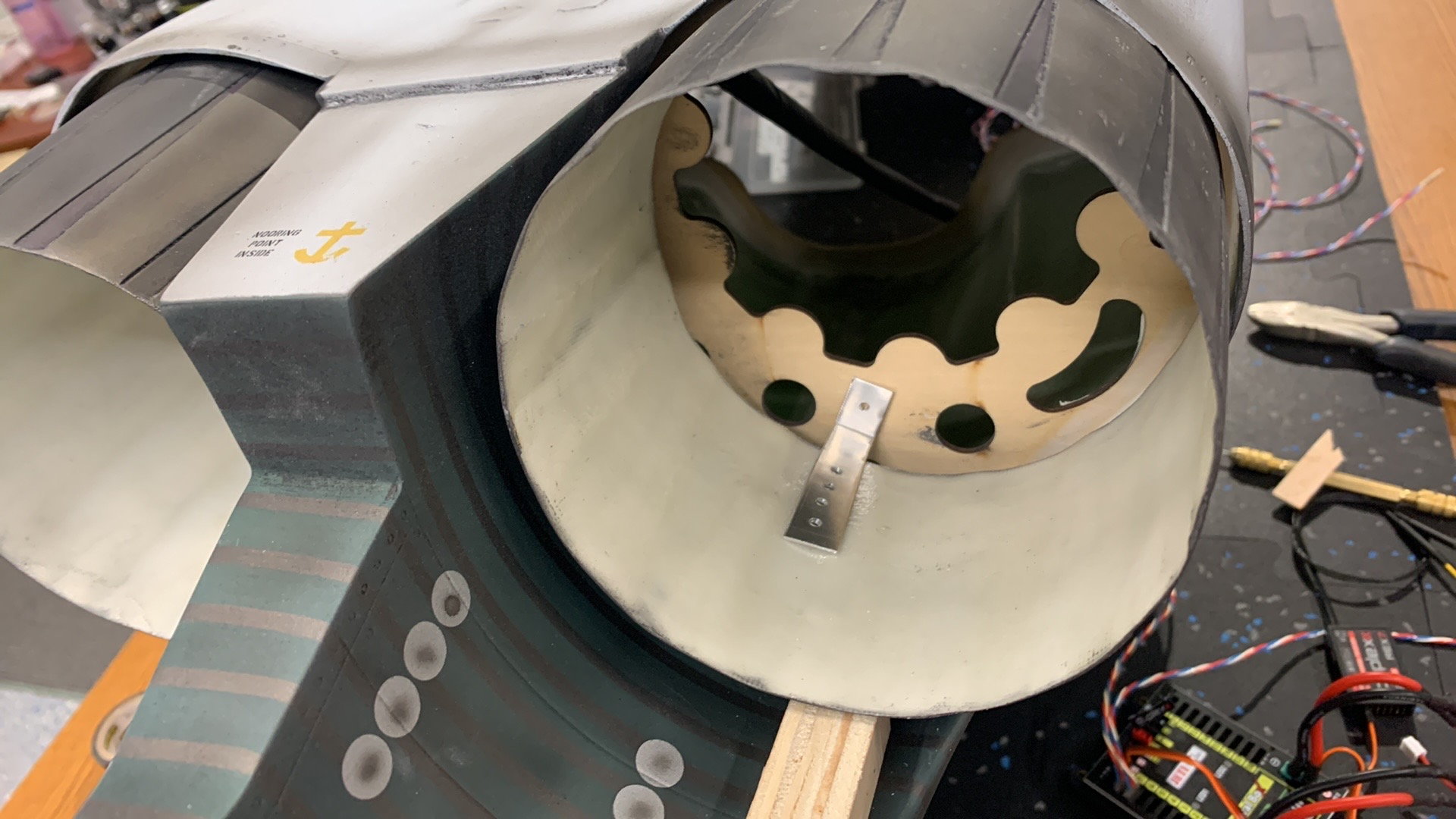
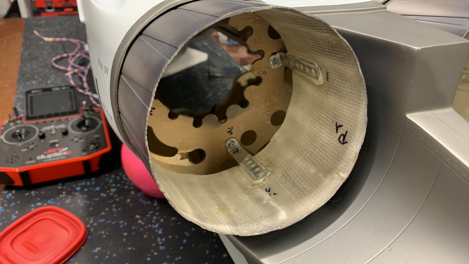
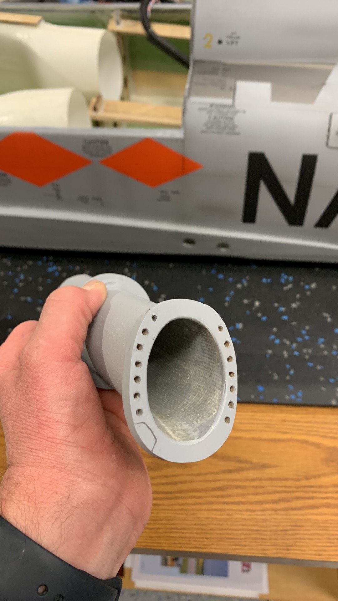
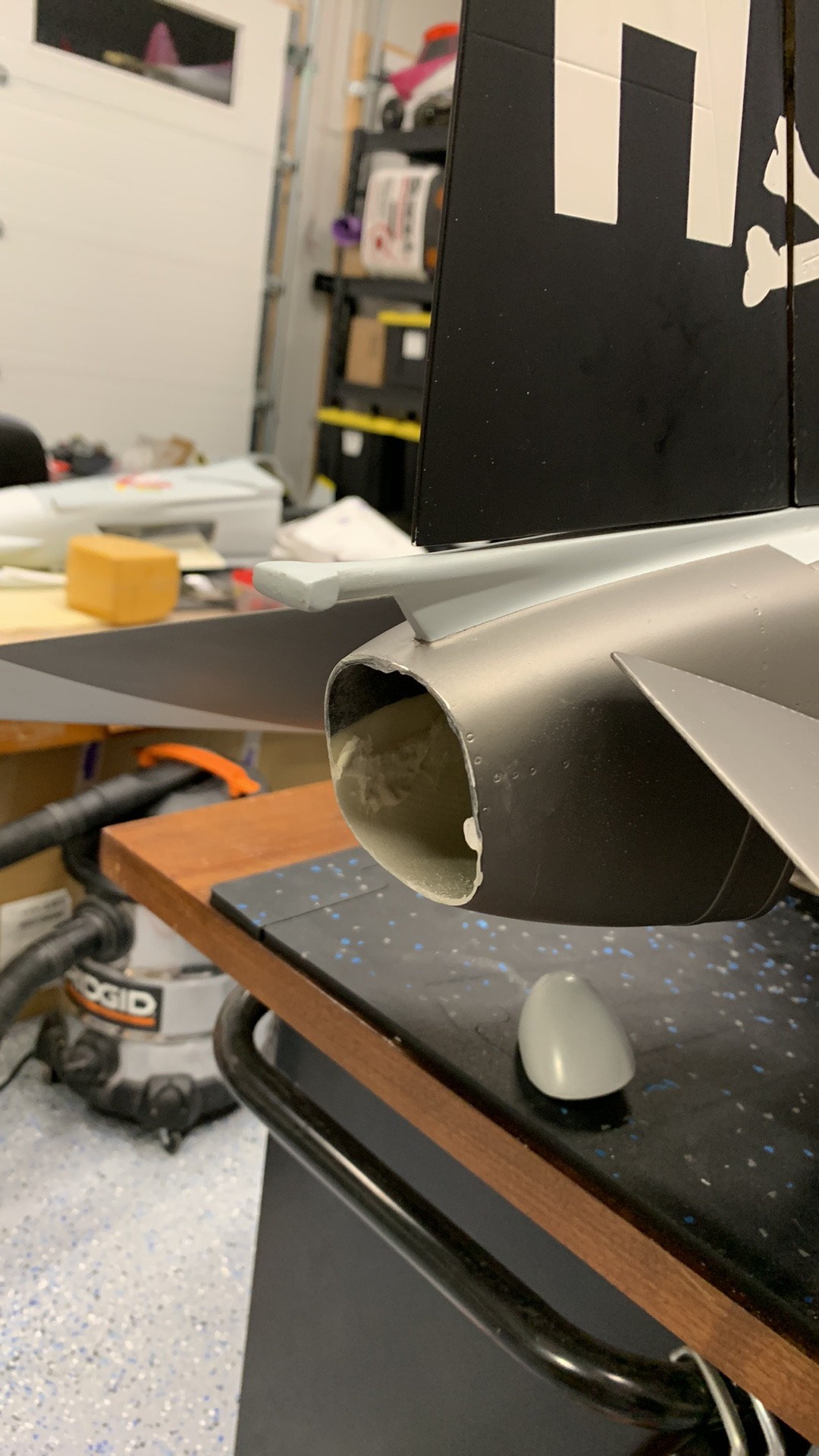
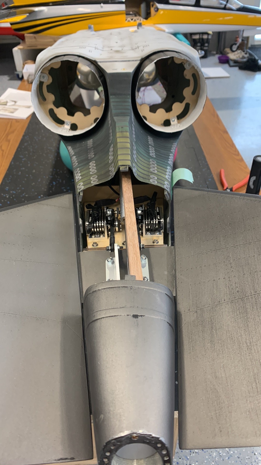
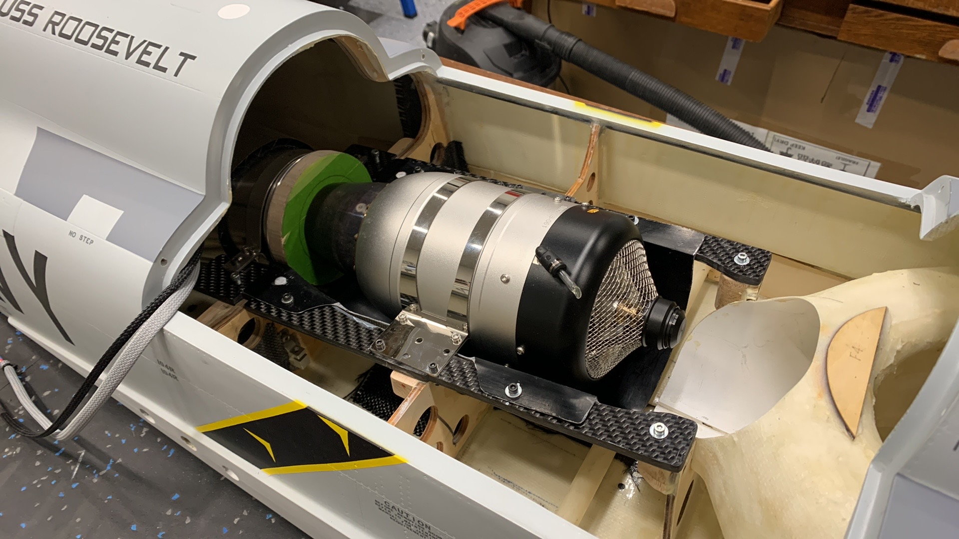
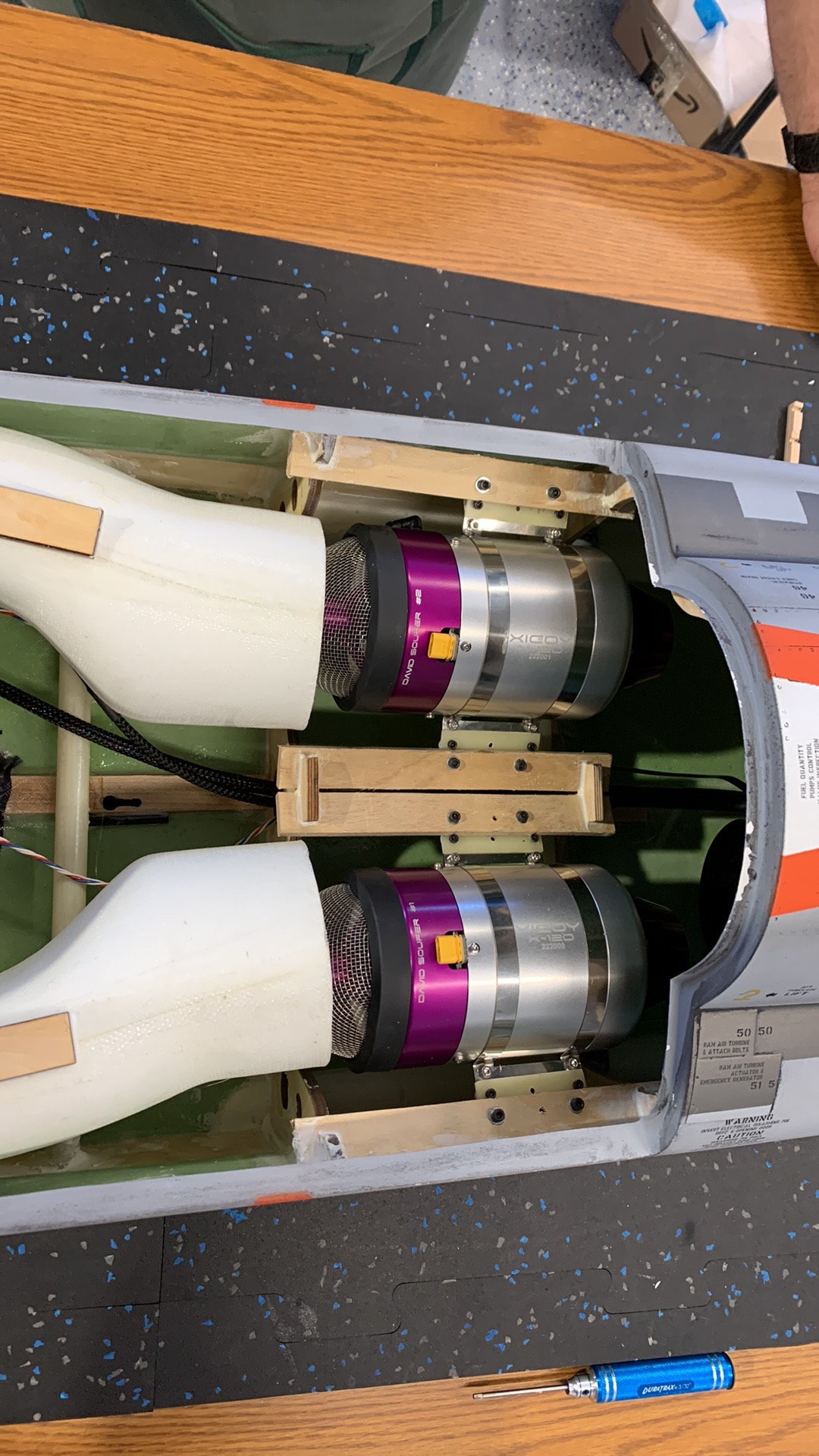
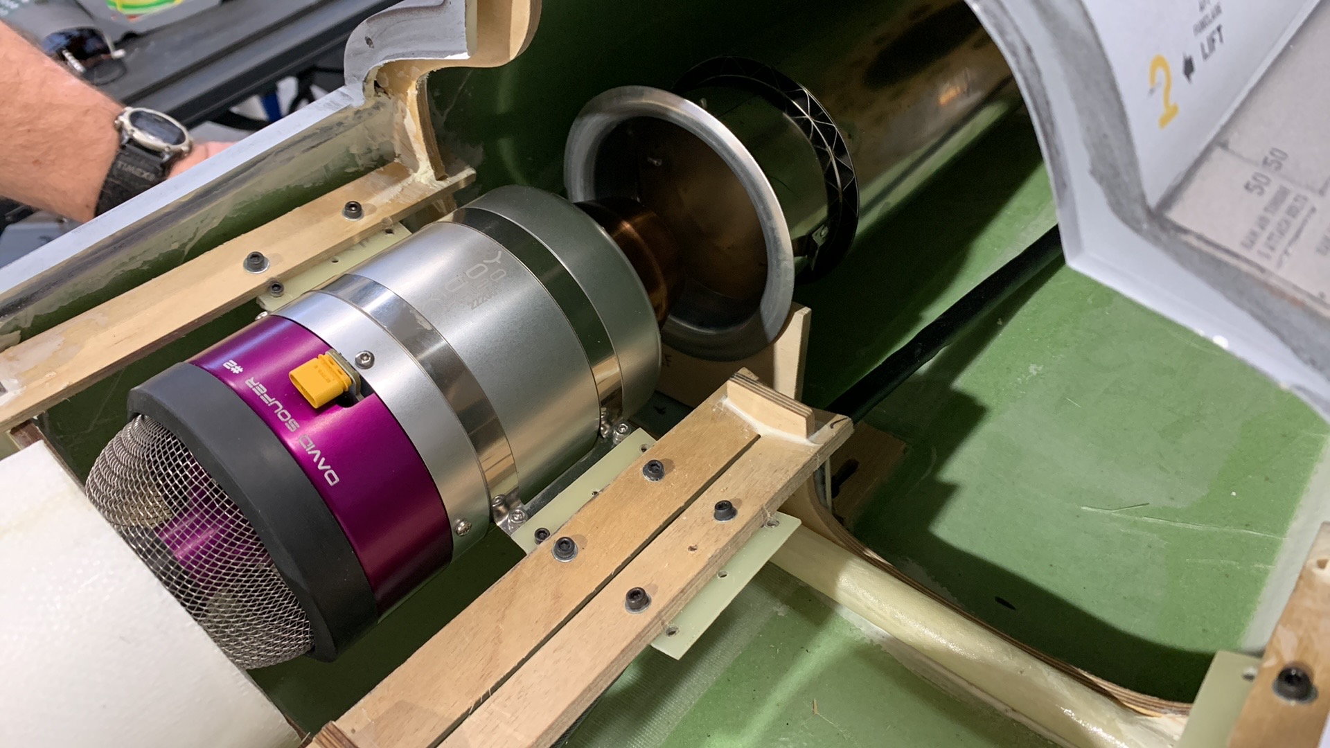
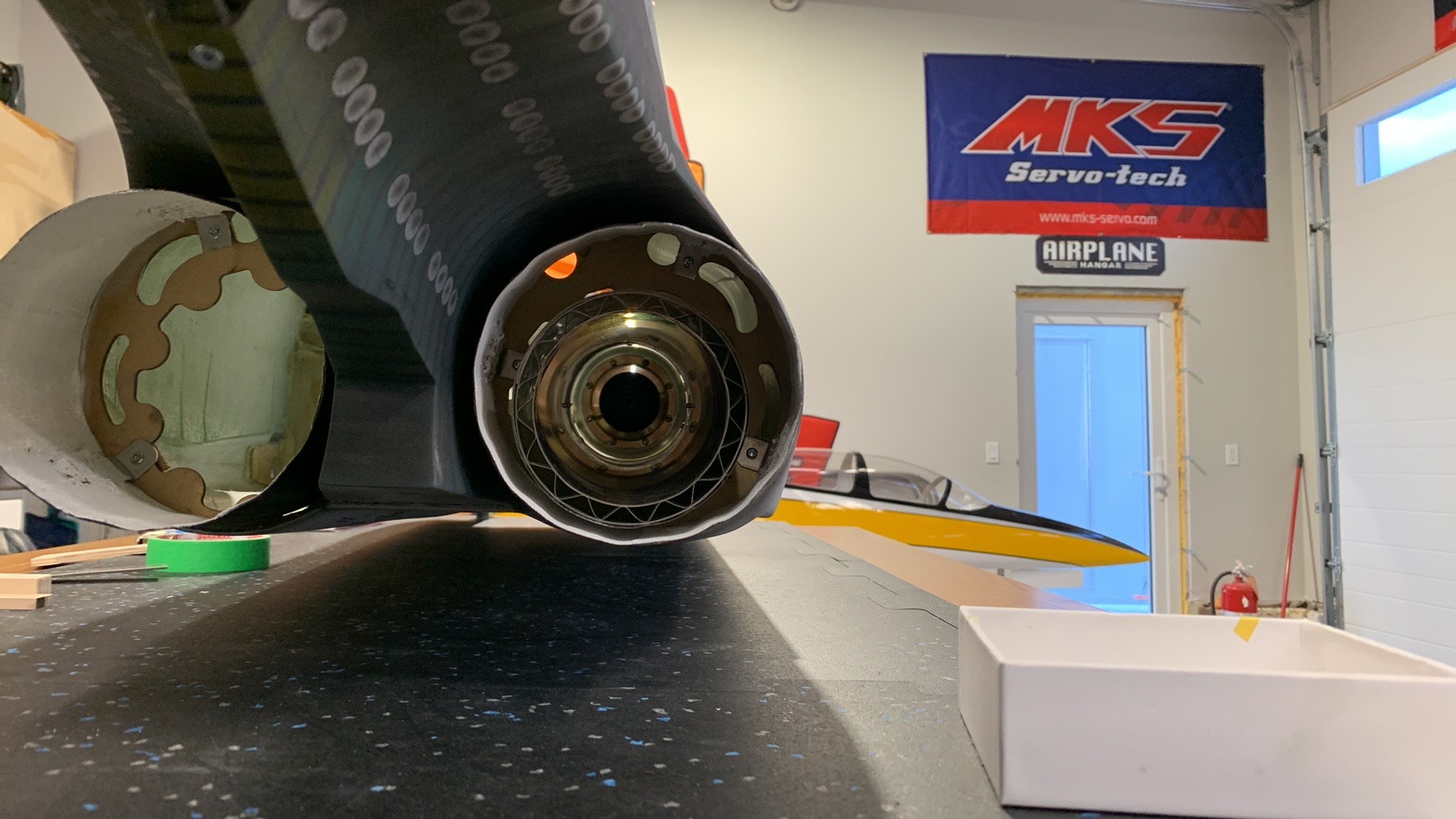
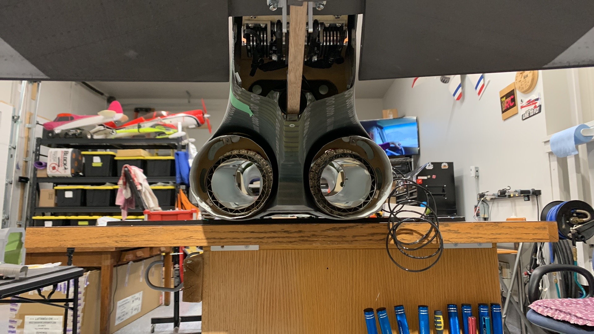
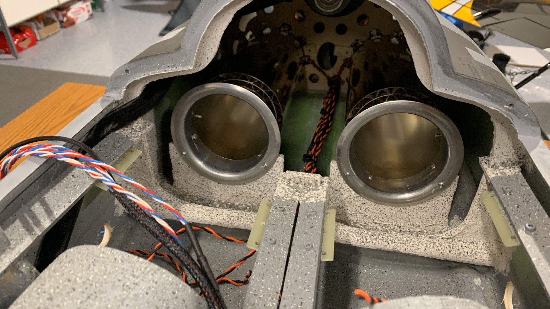
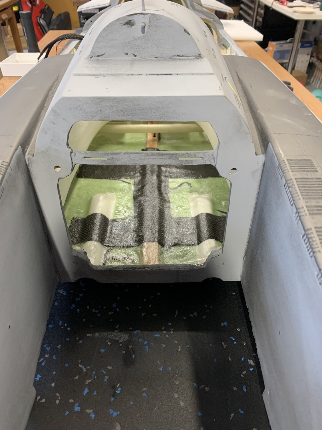
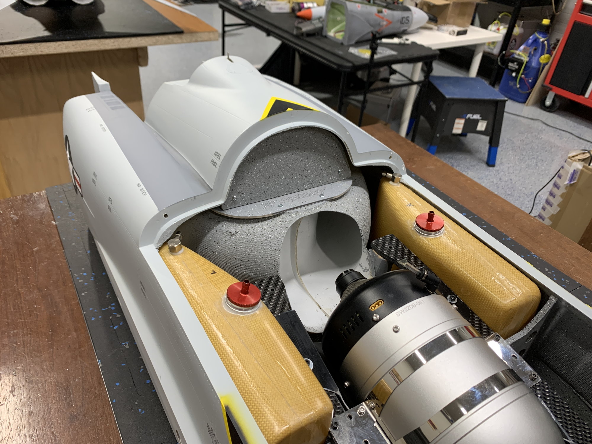
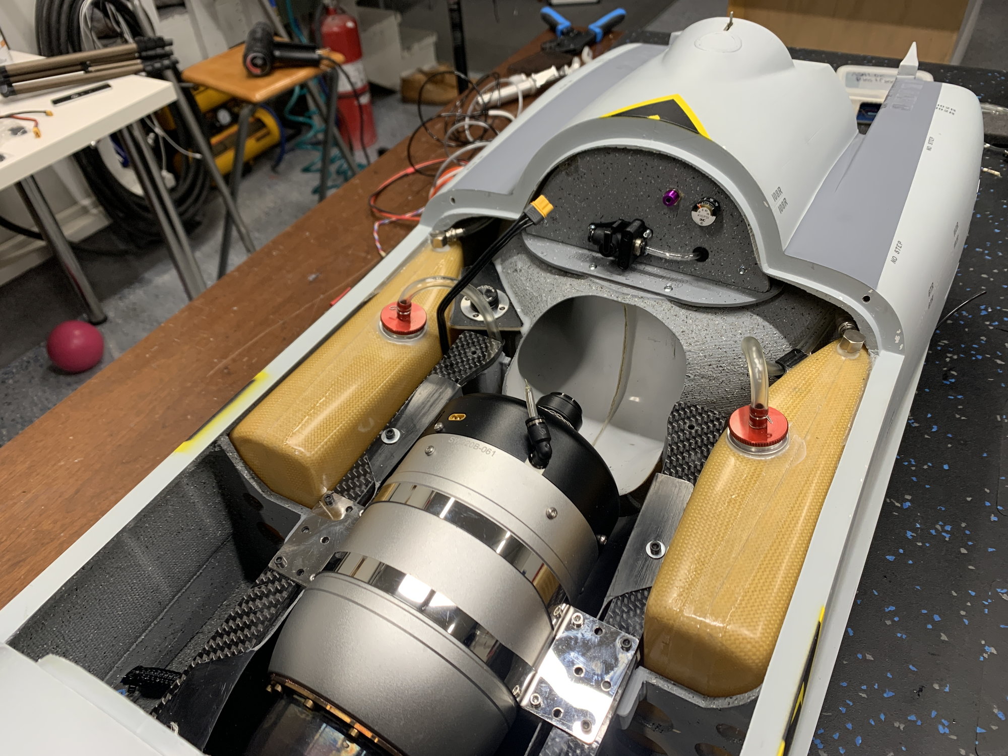
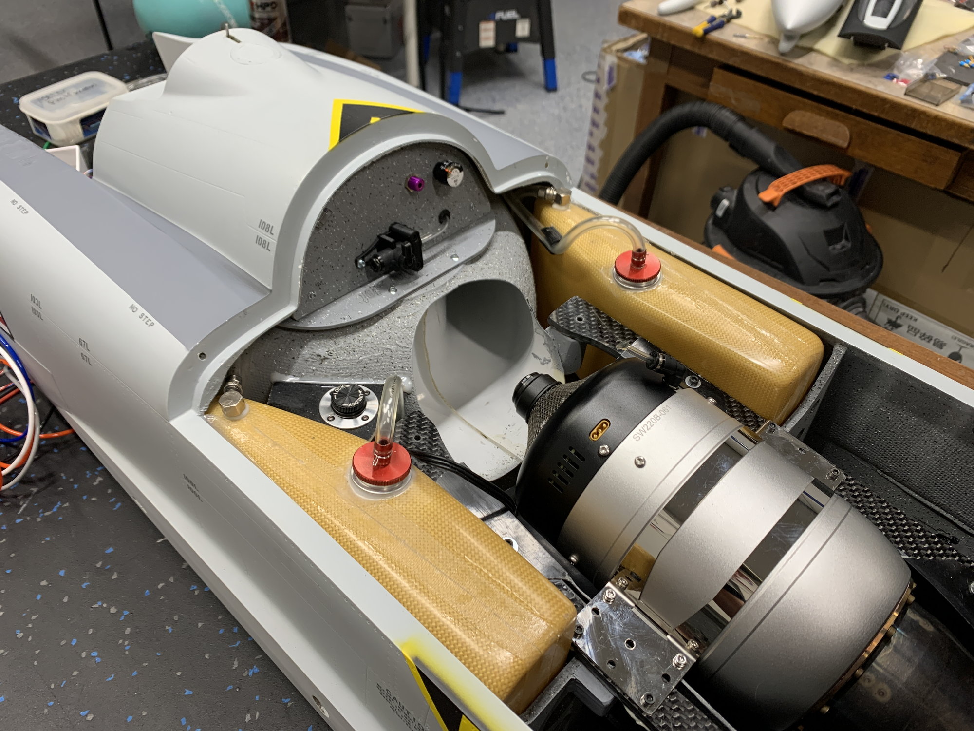
Lining up engine with pipe. Rails have 5 degrees of down added. Pipe is a tams straight pipe so it's all in line at about 5 degrees down.
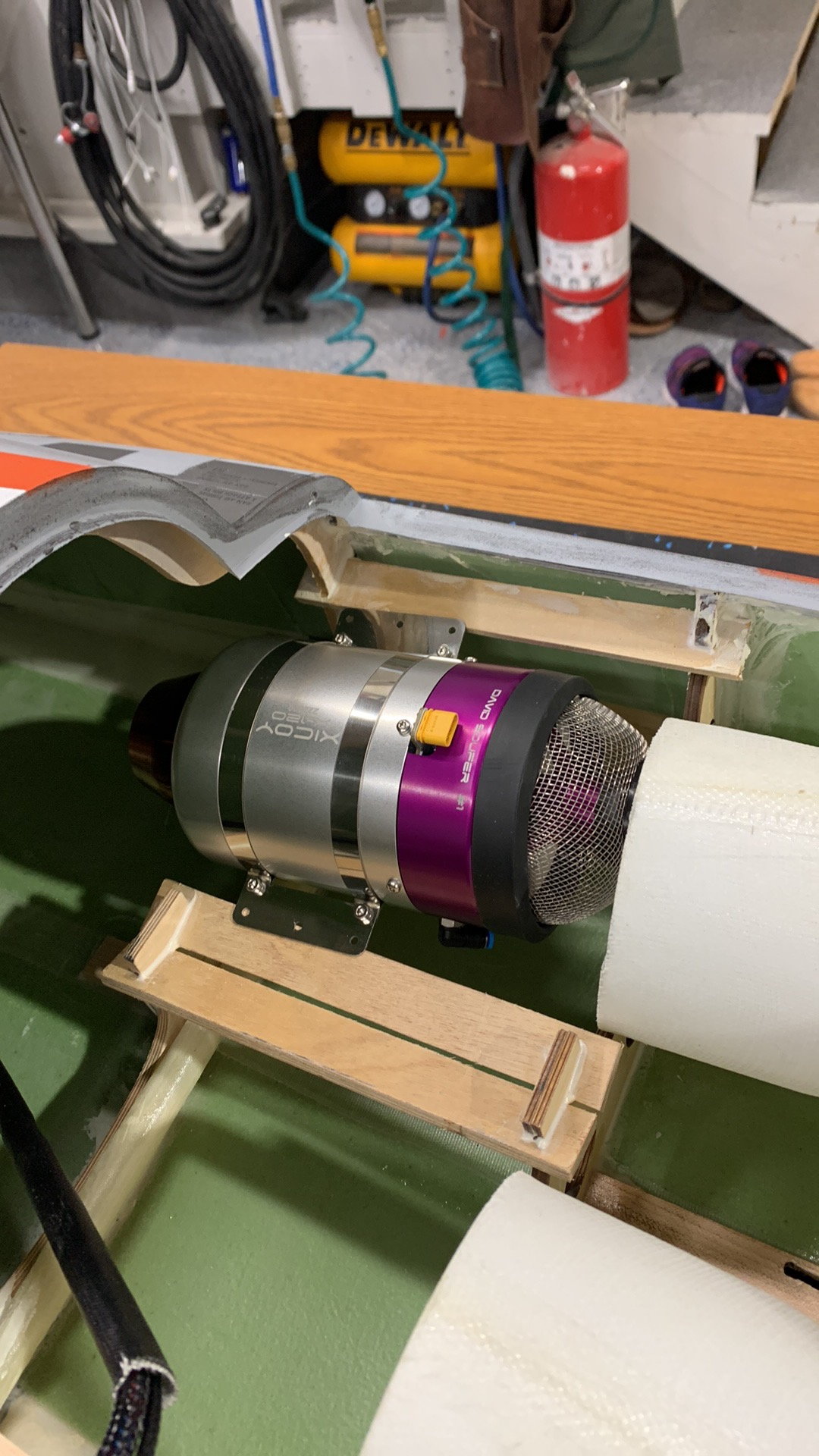
Twin rails have down slope built in. In order to maintain proper slope the turbines needed to be mounted to the underside of the rails.
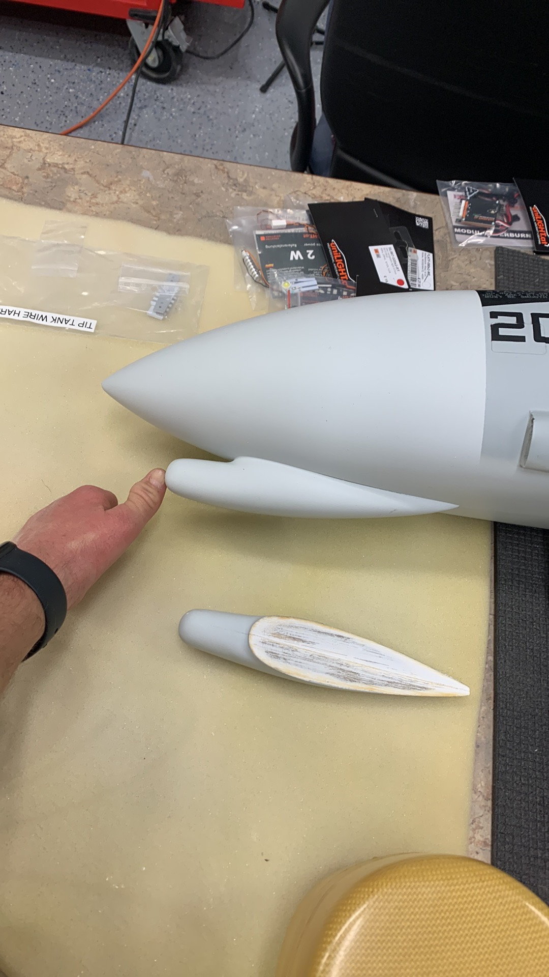
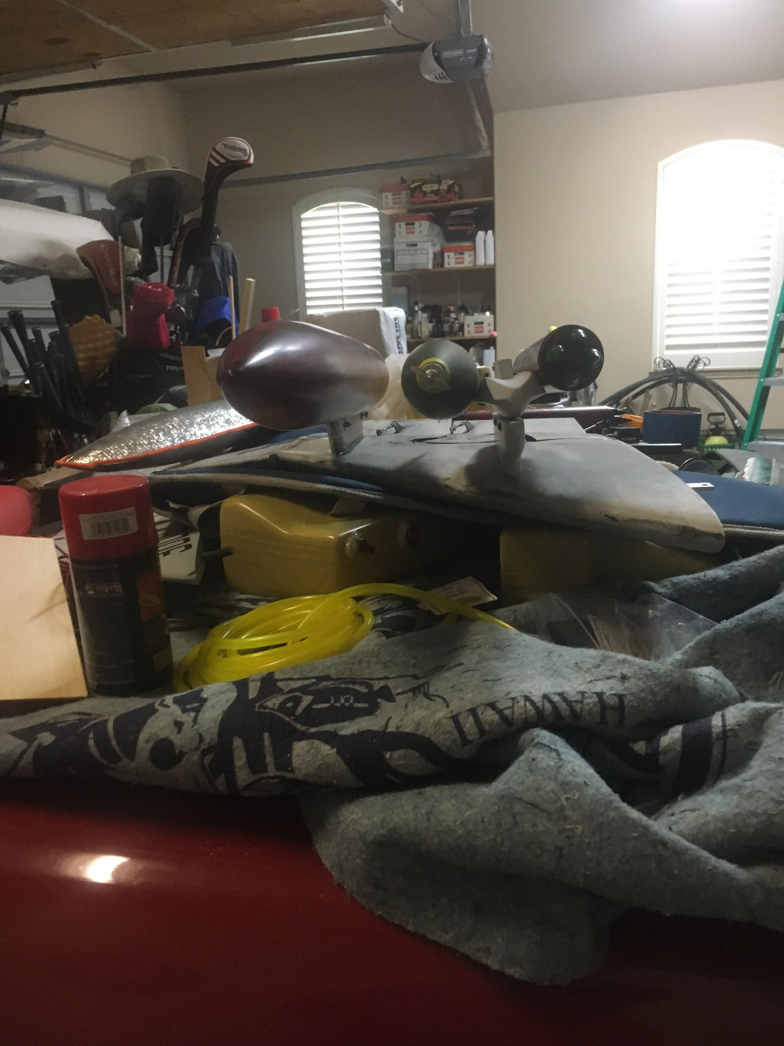
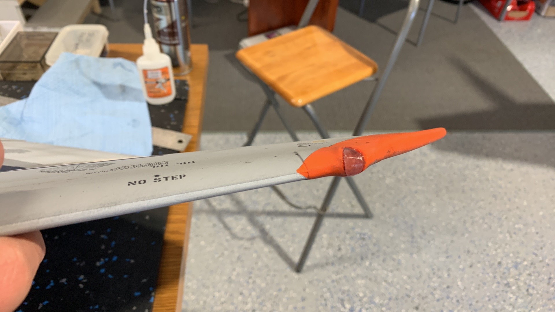
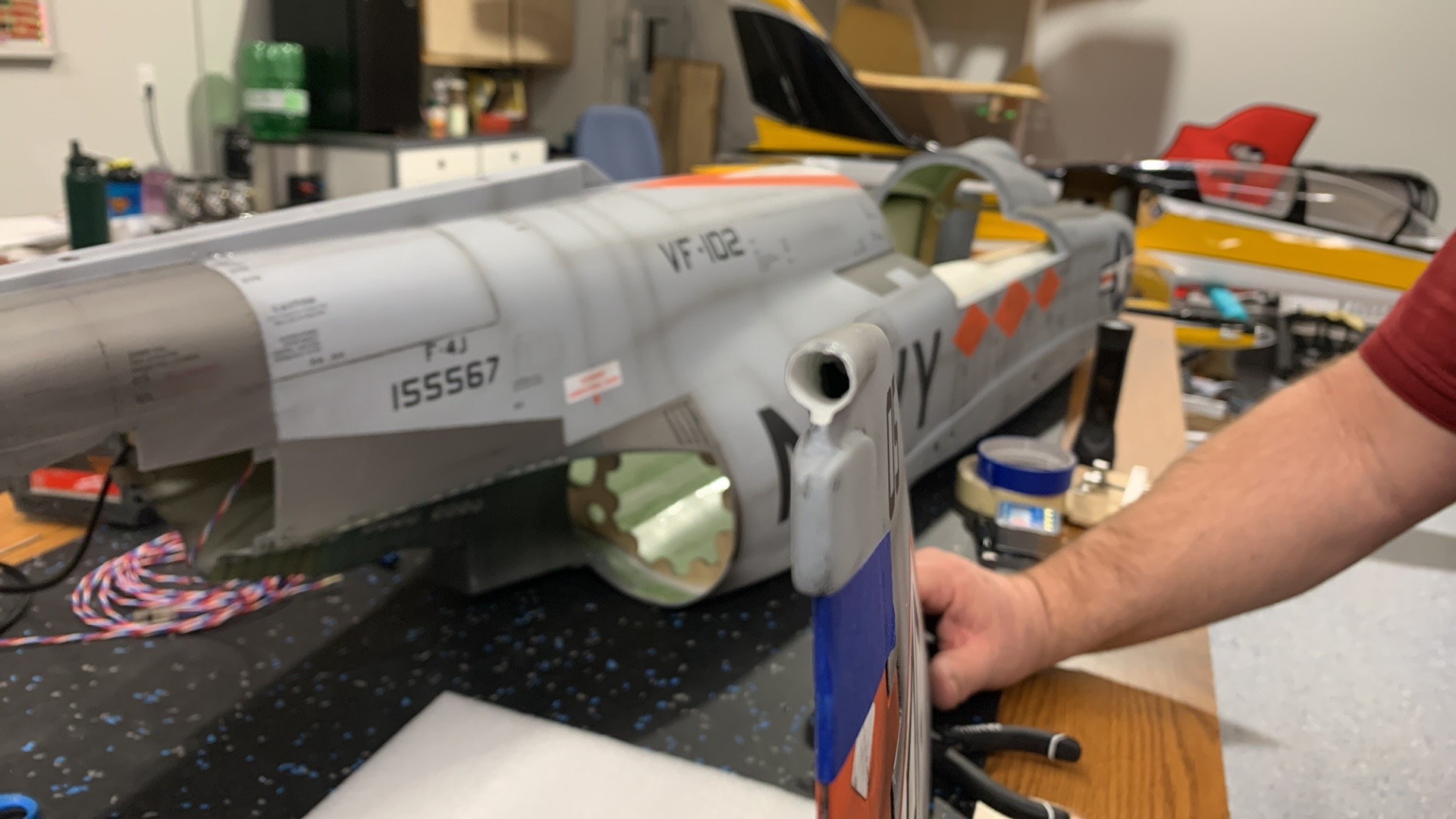
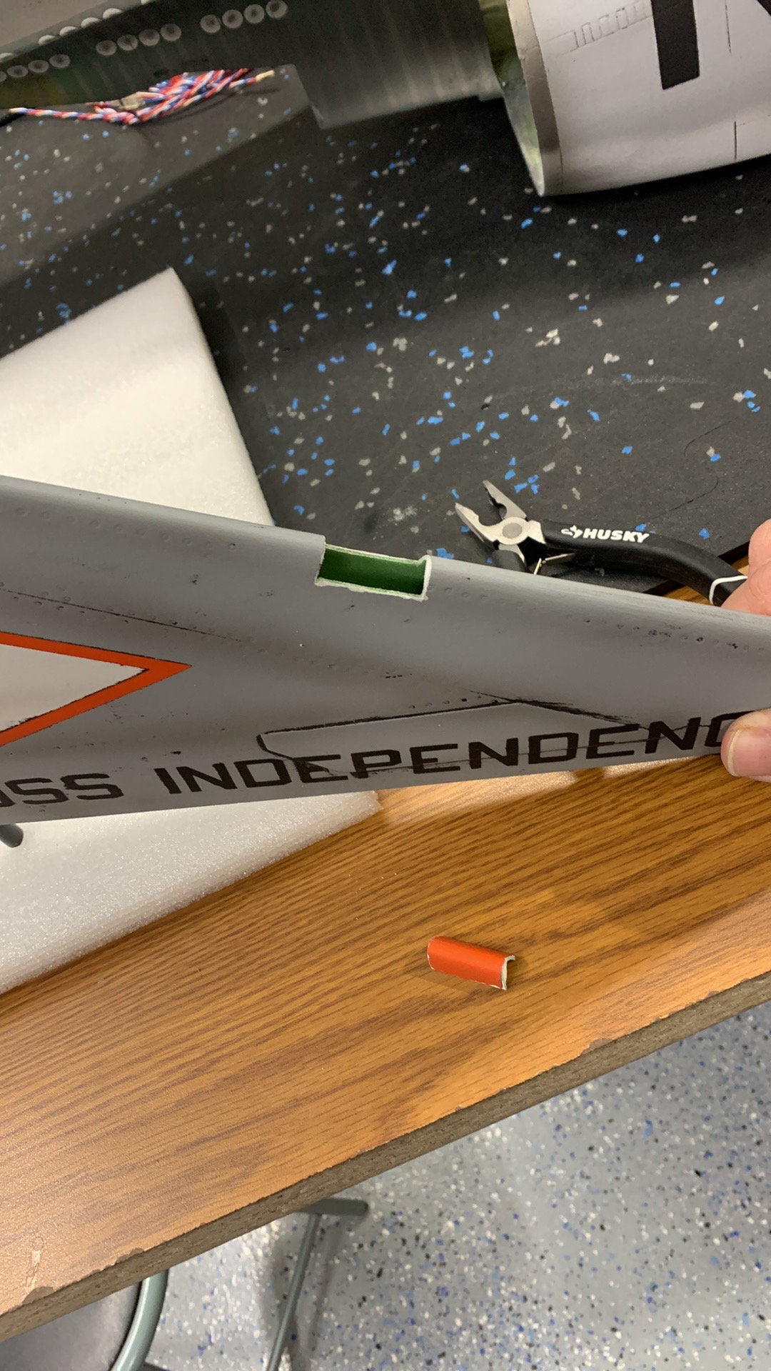
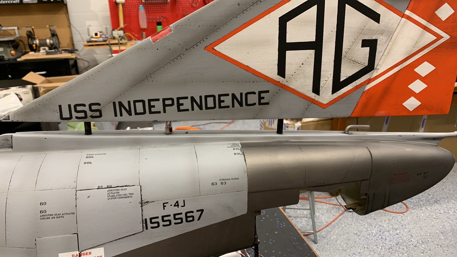
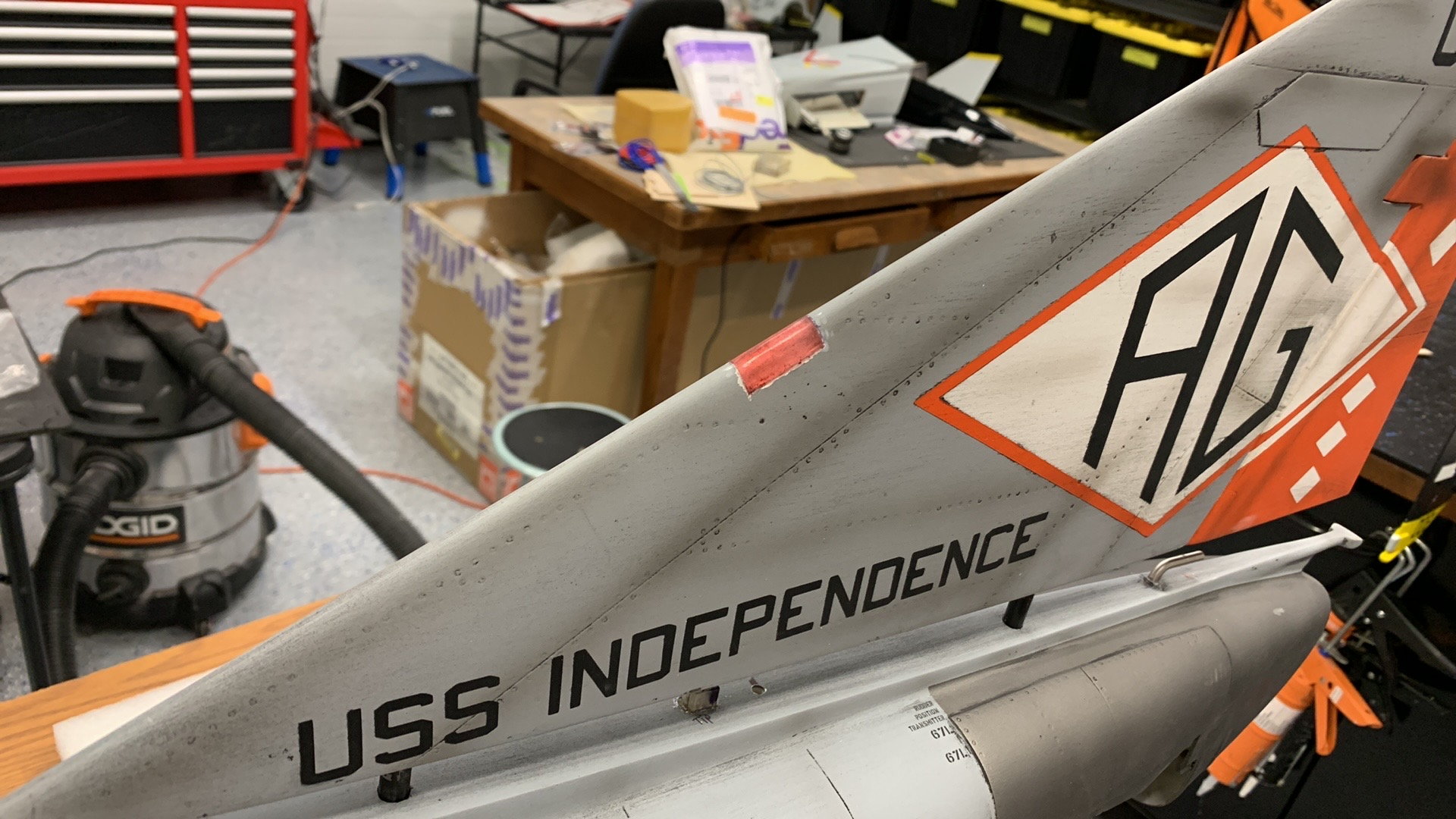
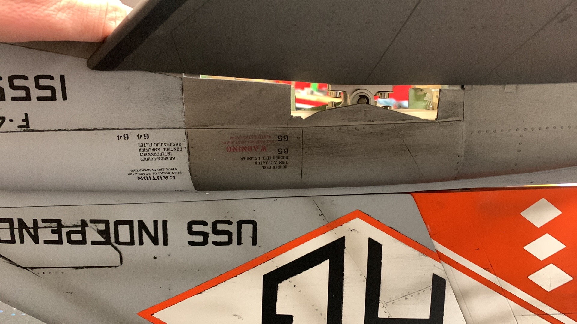
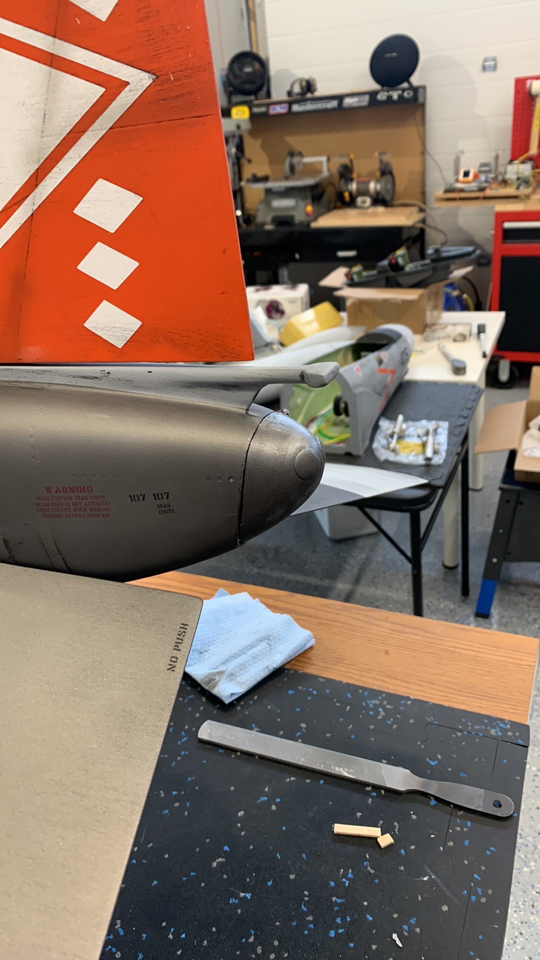
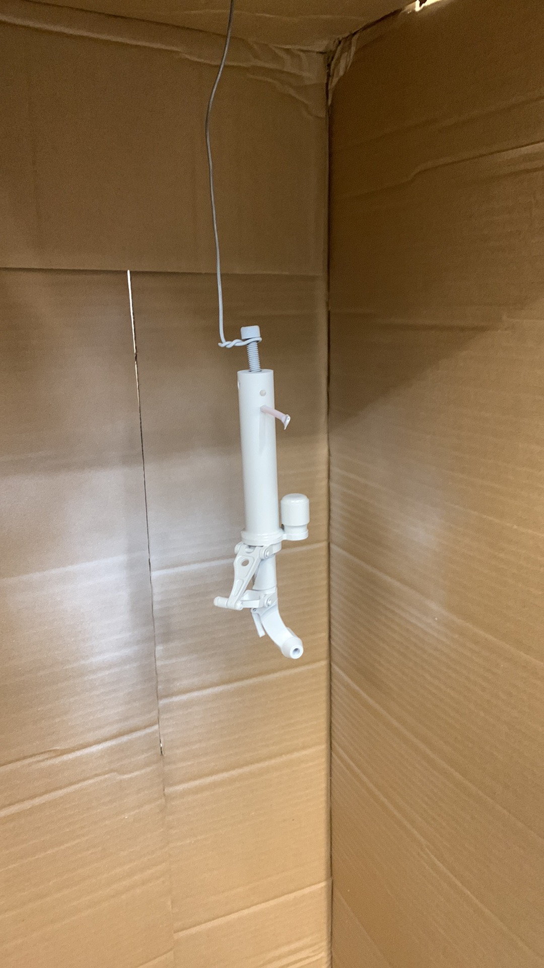
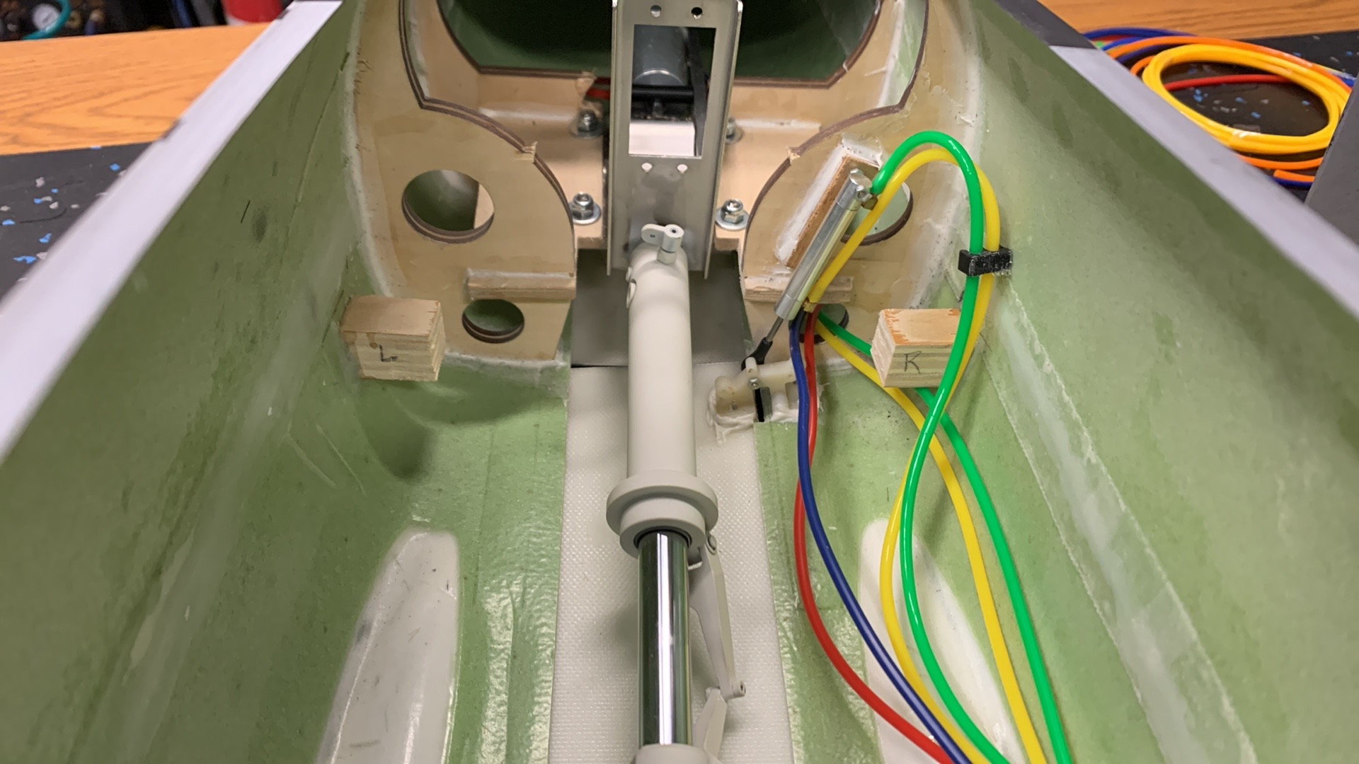
Pitot Tube location on both Aircraft
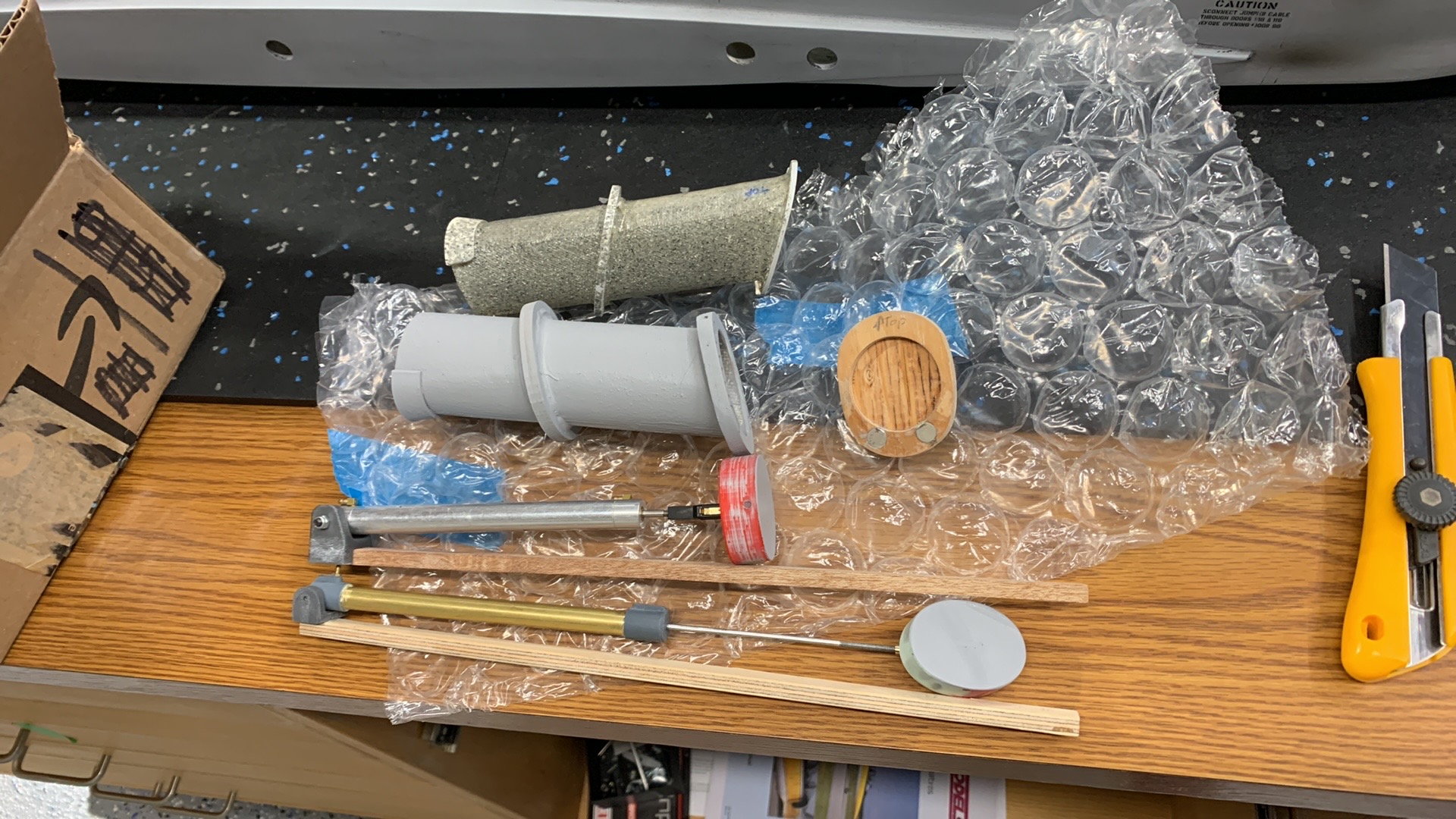
Original detail for scale kit sent off to my 3D Guy and he made up a copy of it. Tube is Fiberglass like the original. We used a Skymaster Air cylinder for chute operation. It's shorter so I added an extension to the shaft.
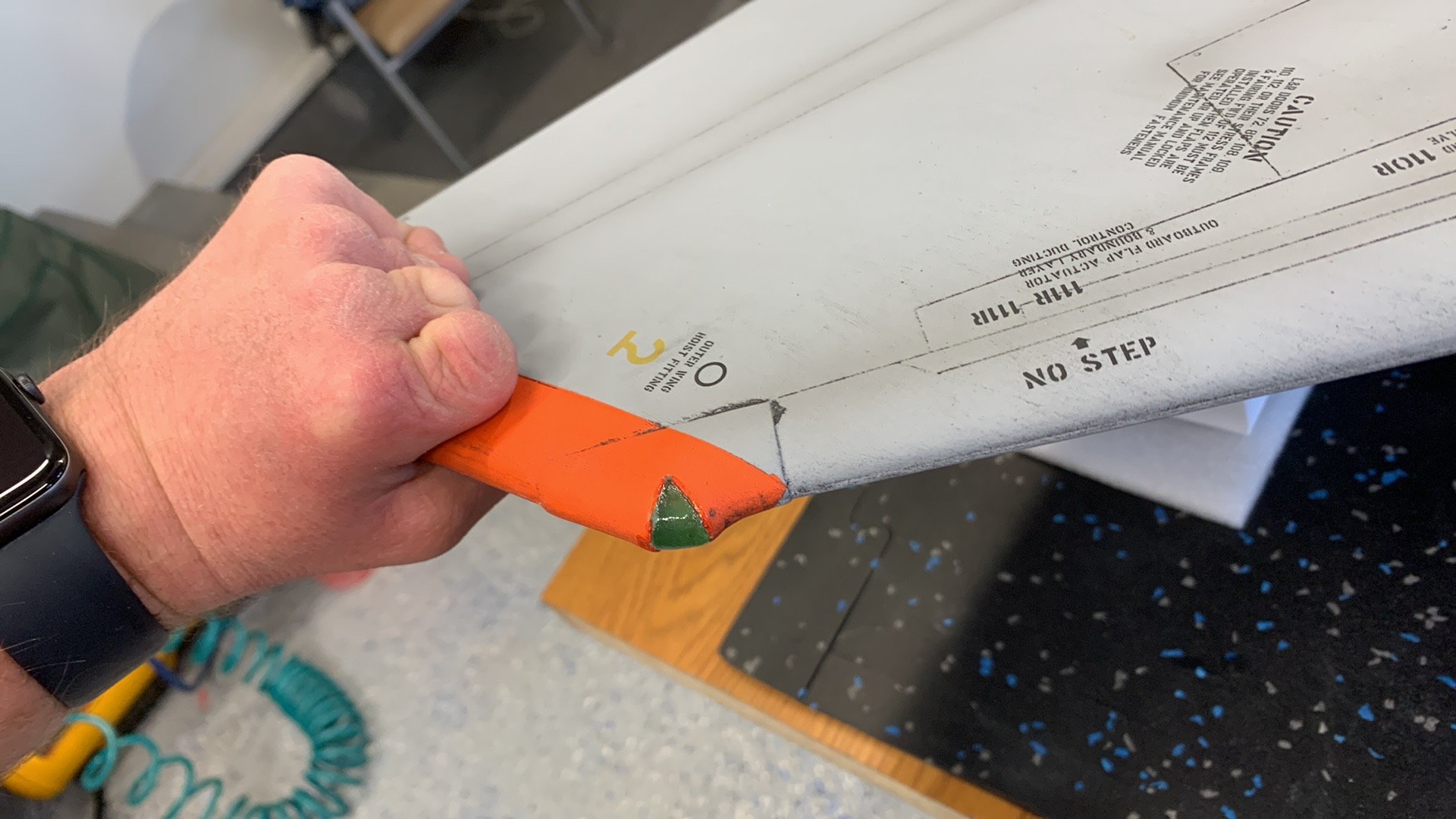
Old kit, I used the new end piece with the detail for scale kit. On the new one we used the cut off tip for this.
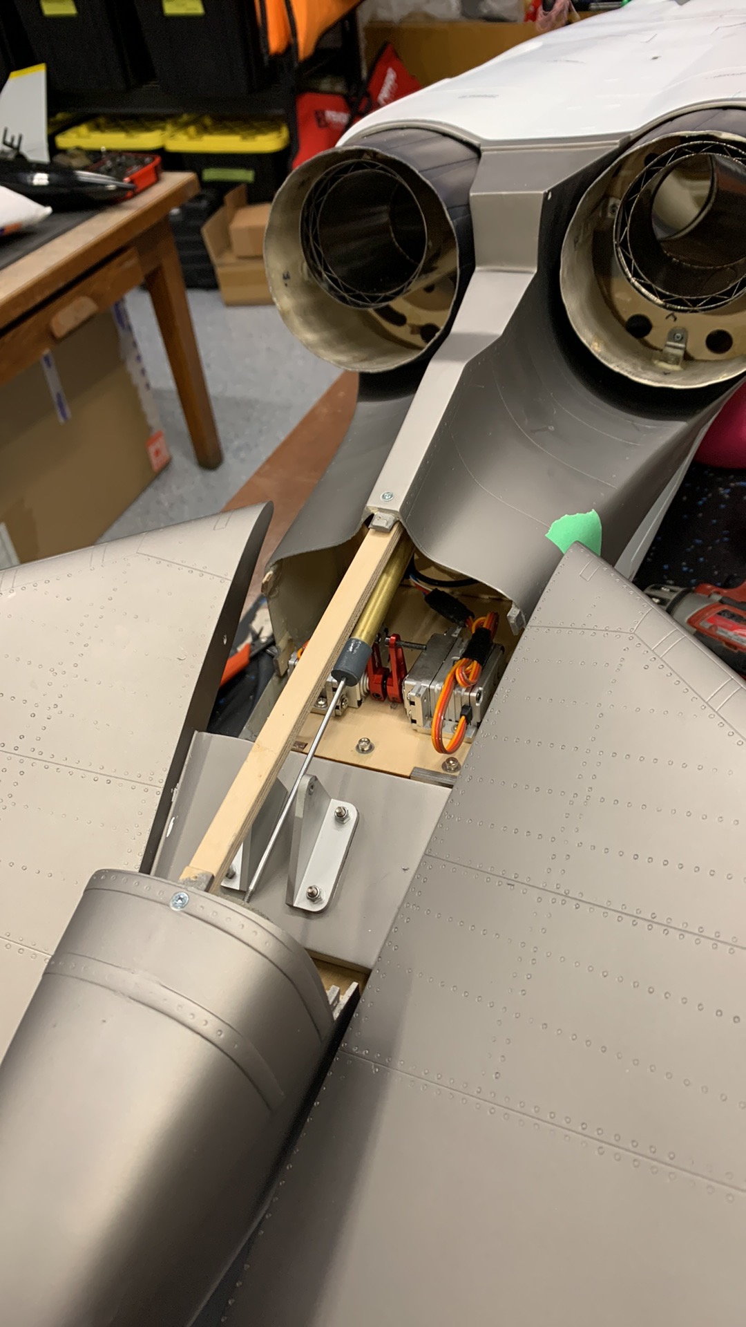
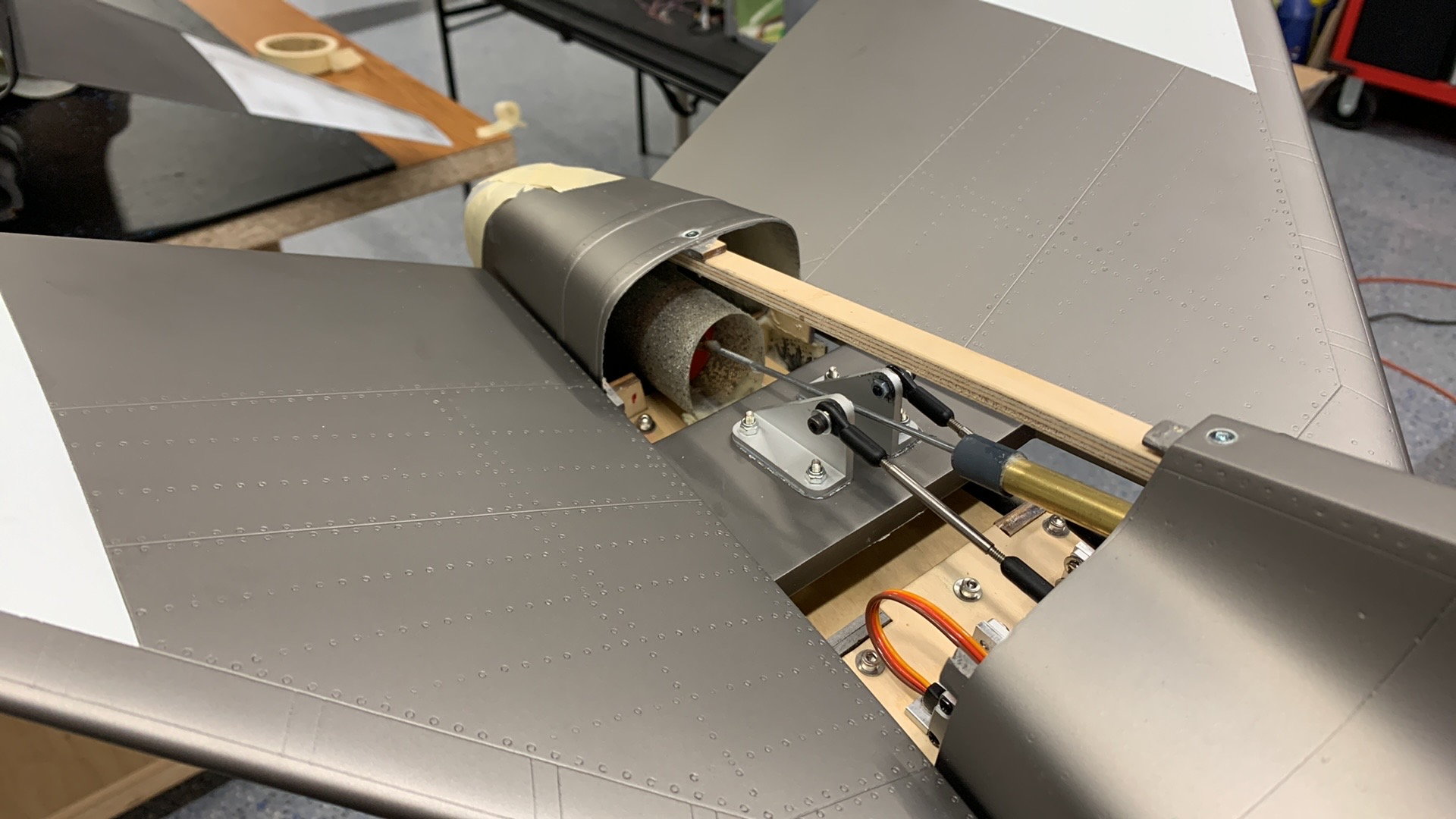
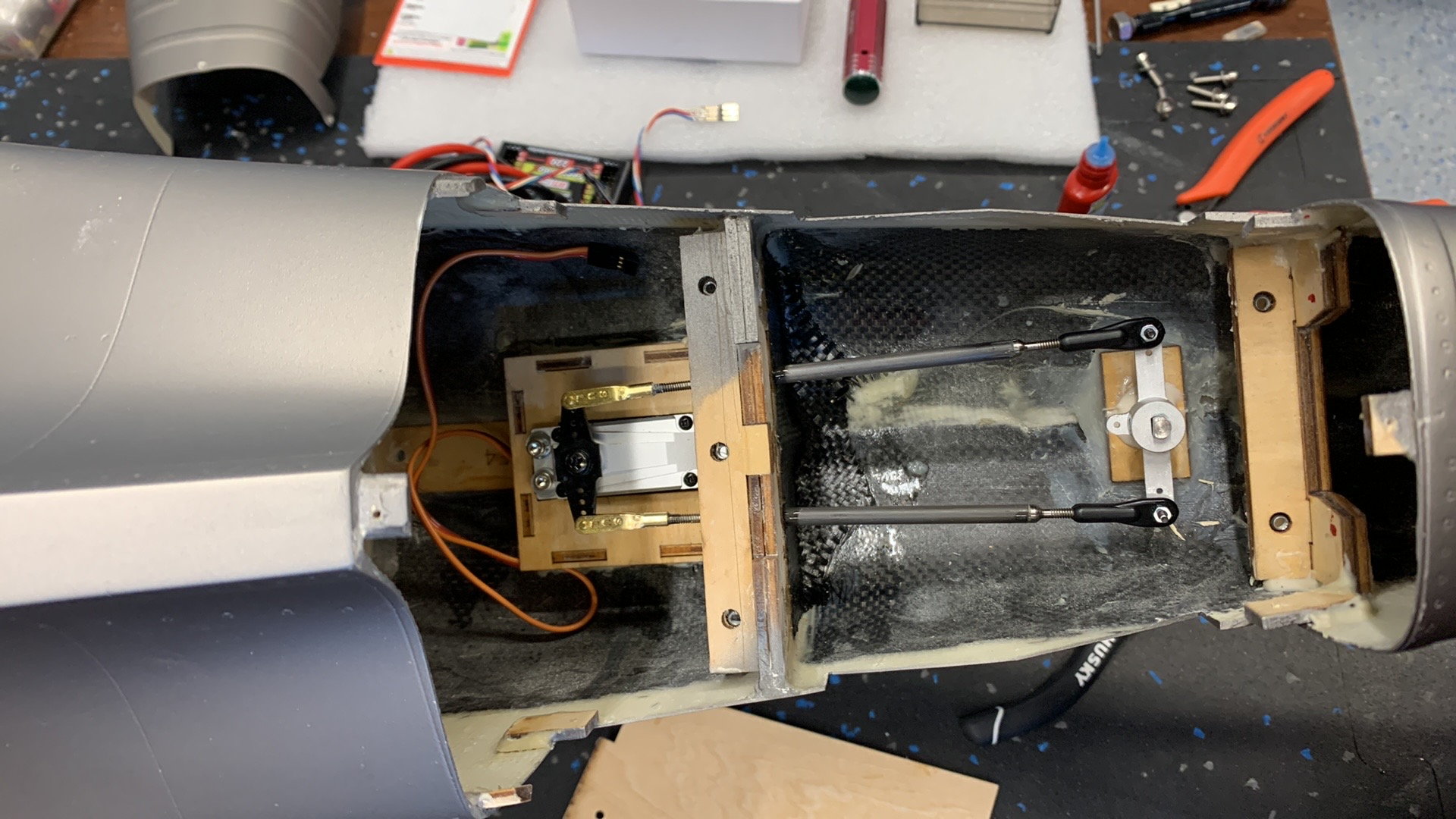
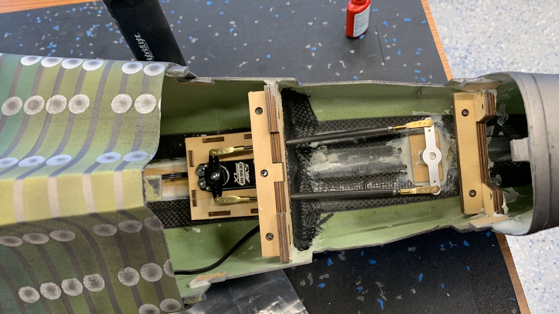
Elevator linkages moved to outside of horns for clearance.
Lining up engine with pipe. Rails have 5 degrees of down added. Pipe is a tams straight pipe so it's all in line at about 5 degrees down.
Twin rails have down slope built in. In order to maintain proper slope the turbines needed to be mounted to the underside of the rails.
Pitot Tube location on both Aircraft
Original detail for scale kit sent off to my 3D Guy and he made up a copy of it. Tube is Fiberglass like the original. We used a Skymaster Air cylinder for chute operation. It's shorter so I added an extension to the shaft.
Old kit, I used the new end piece with the detail for scale kit. On the new one we used the cut off tip for this.
Elevator linkages moved to outside of horns for clearance.
02-22-2023, 09:06 AM
#544
My Feedback: (1)
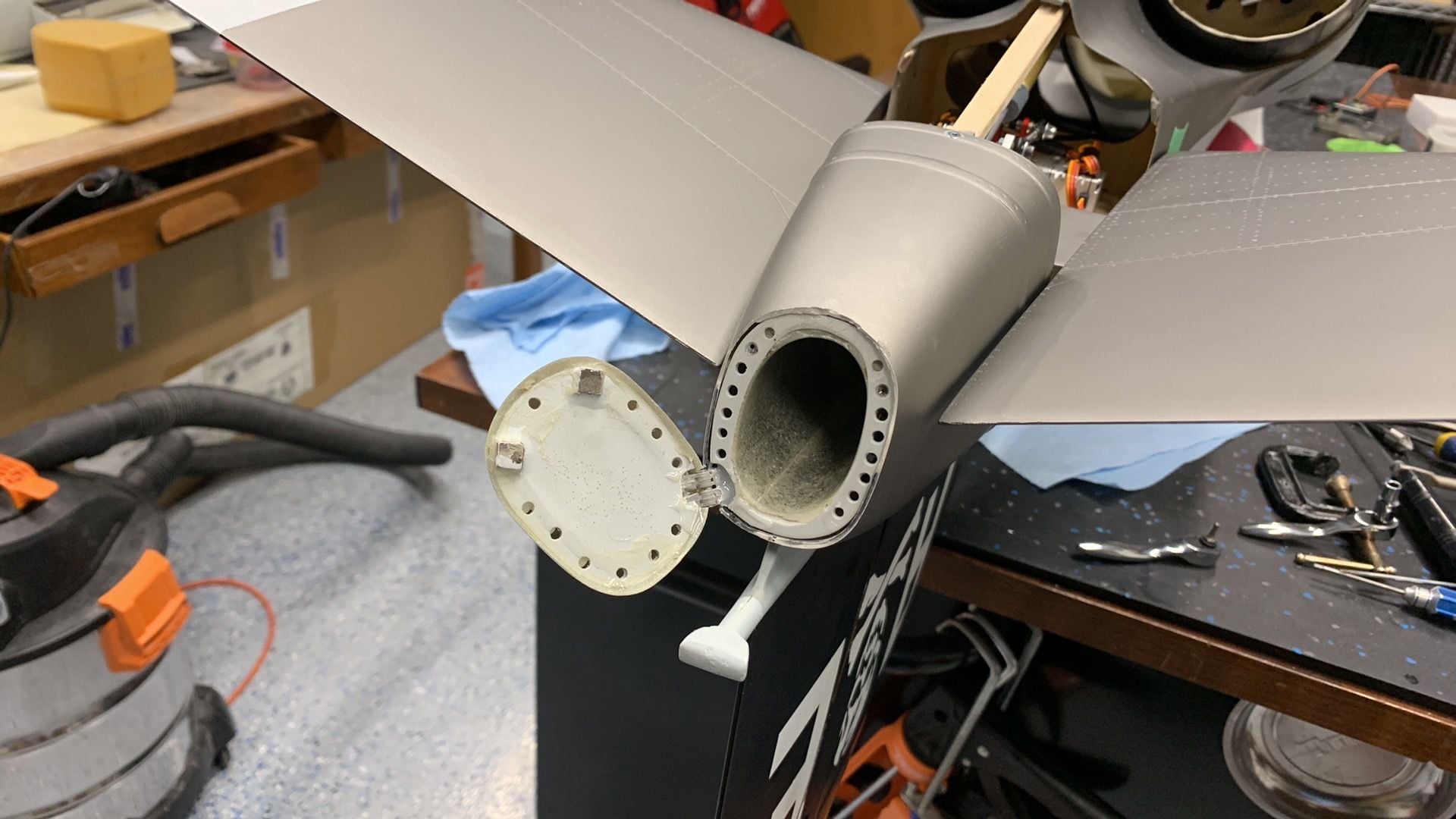
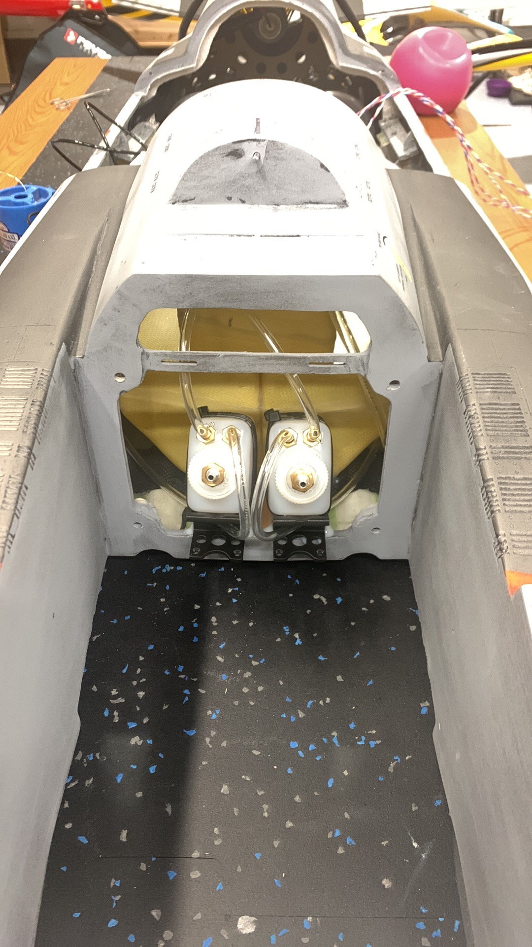
New twin chute hatch complete. Uses original cut off.
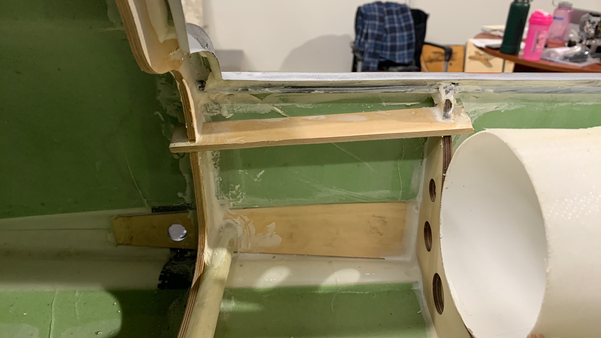
G10 plates made and fastened in place. Nuts glued to backside of turbine mounts so easy removal and G10 plates stay put.
Beautiful alignment!
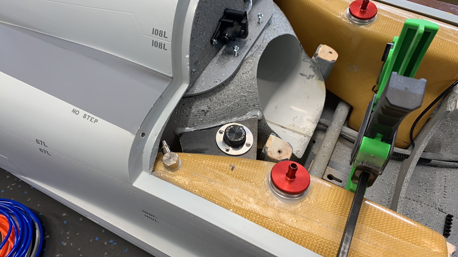
Skymaster stock bungs need an aluminum fitting to seal properly. In this case we used MAP (Model Aviation Products) Fuel fitting kit.
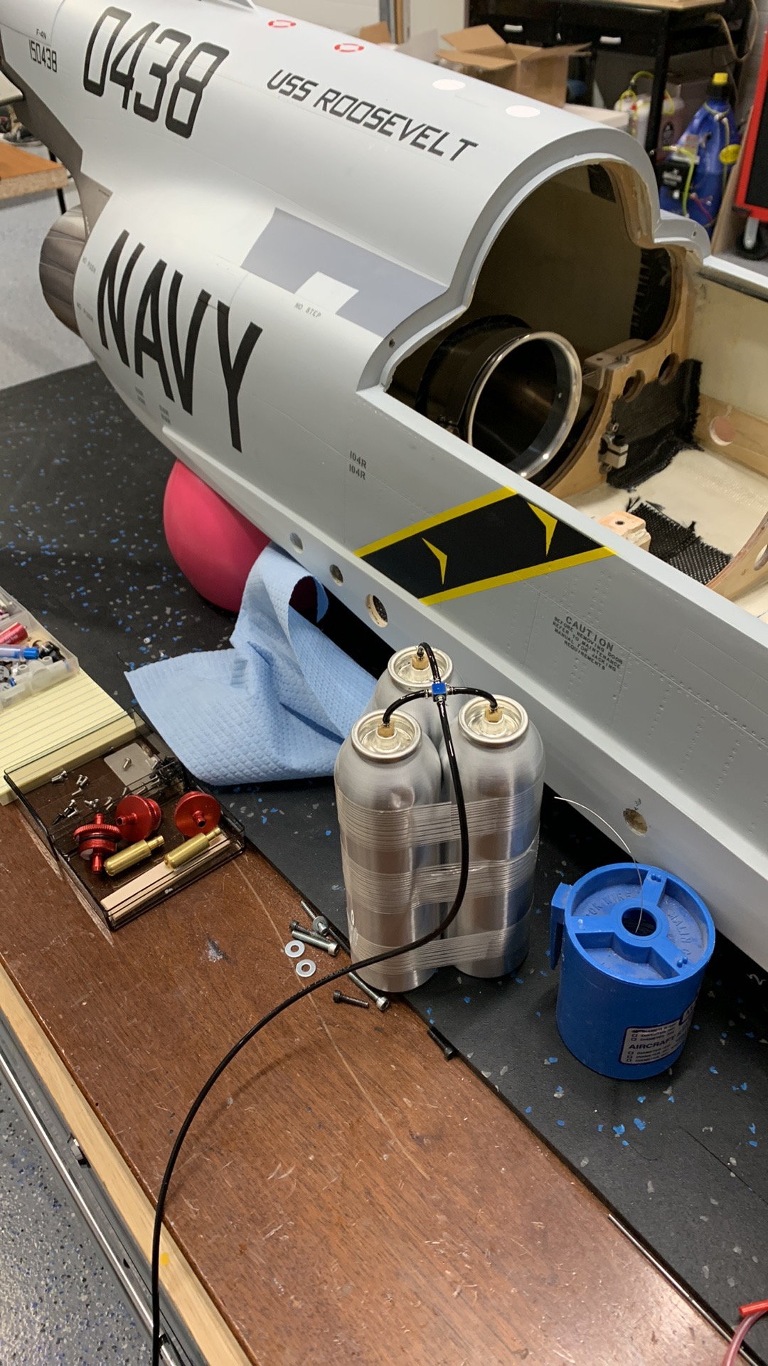
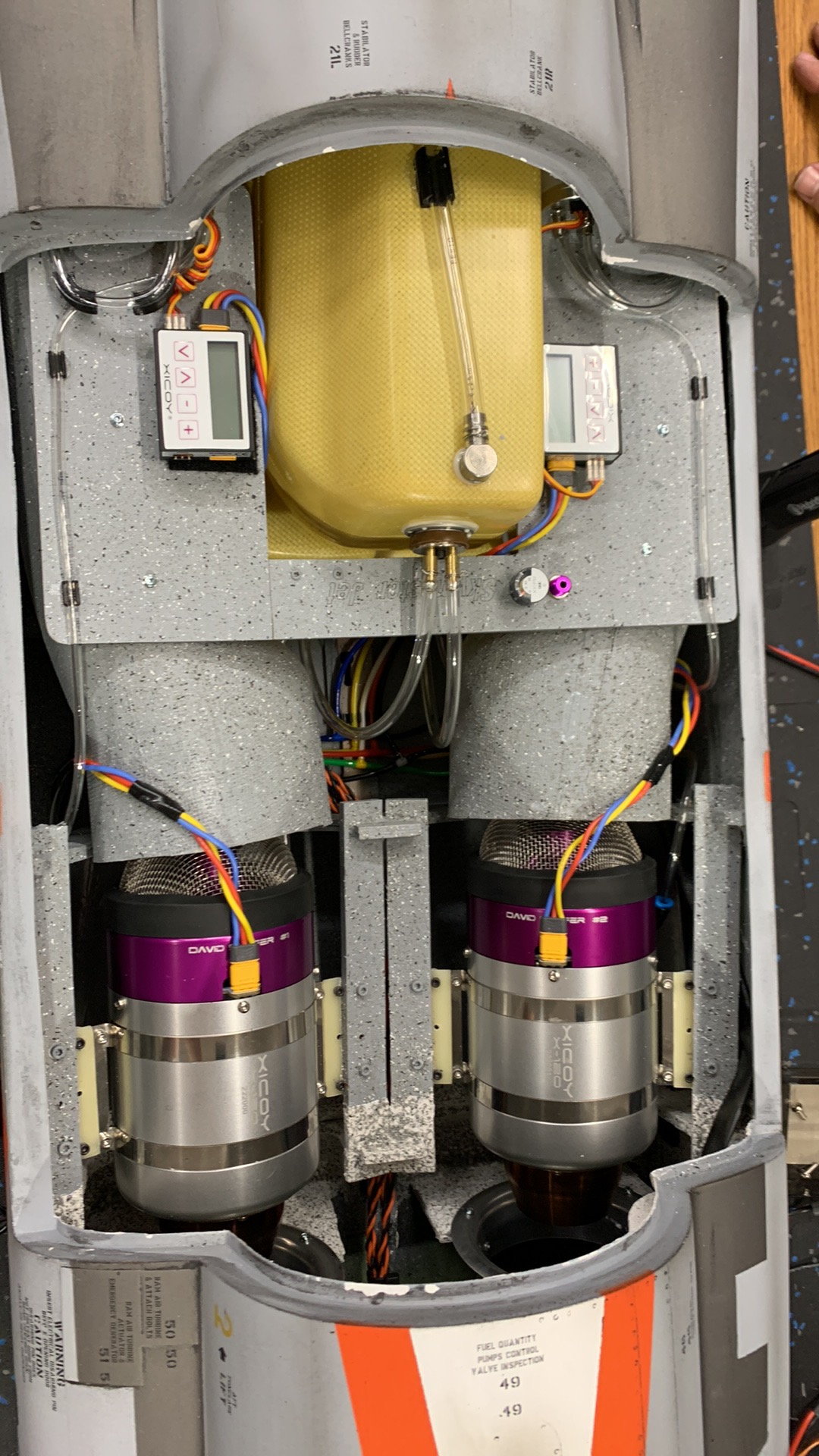
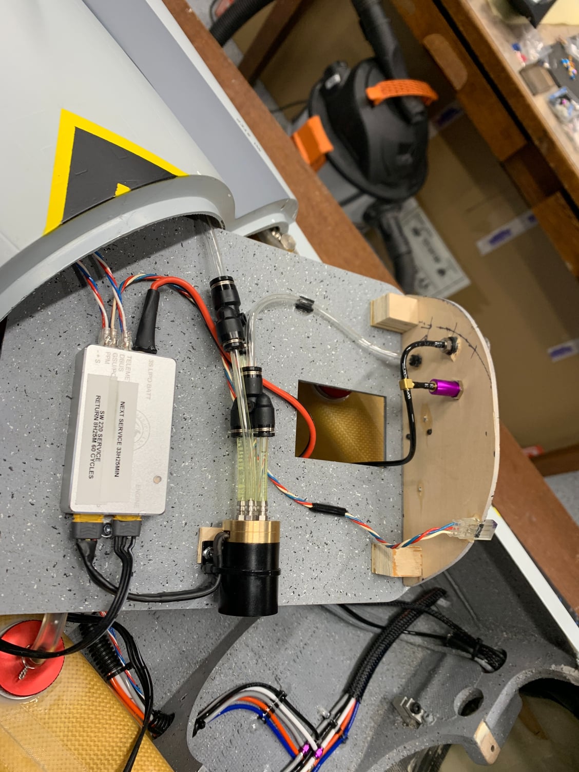
3 air takes used for the entire plane. all plumbed together. Both aircraft get a Vspeak onboard compressor.
02-22-2023, 09:17 AM
#545
My Feedback: (1)
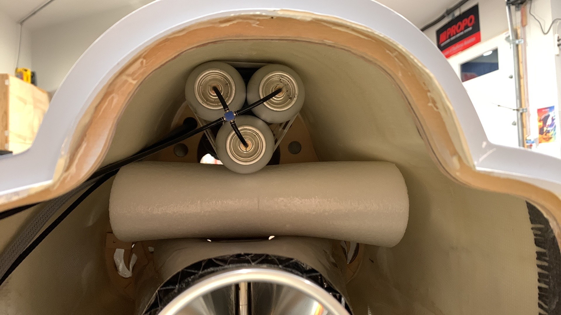
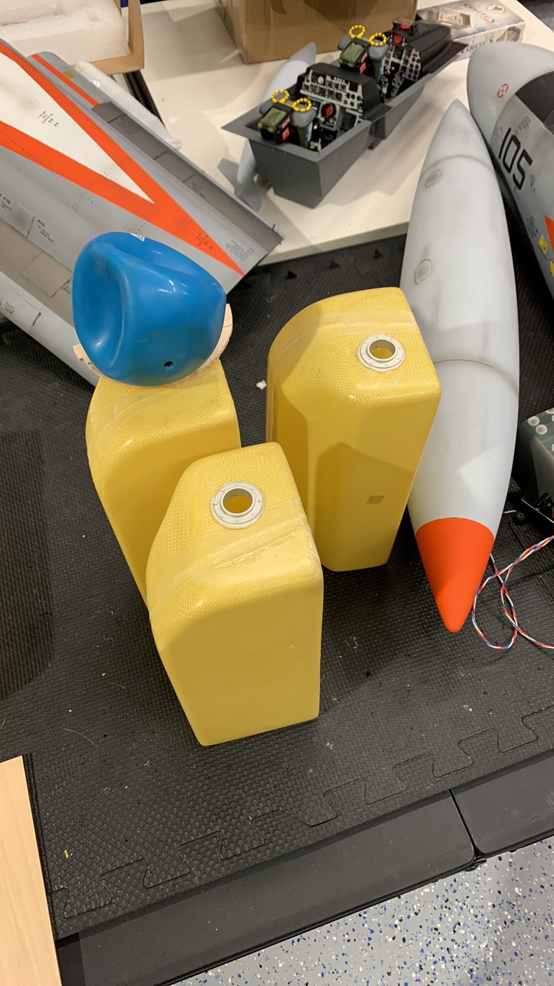
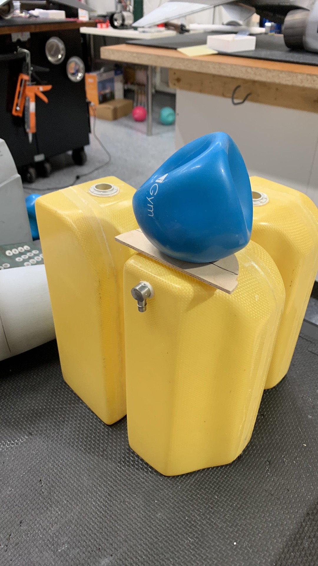
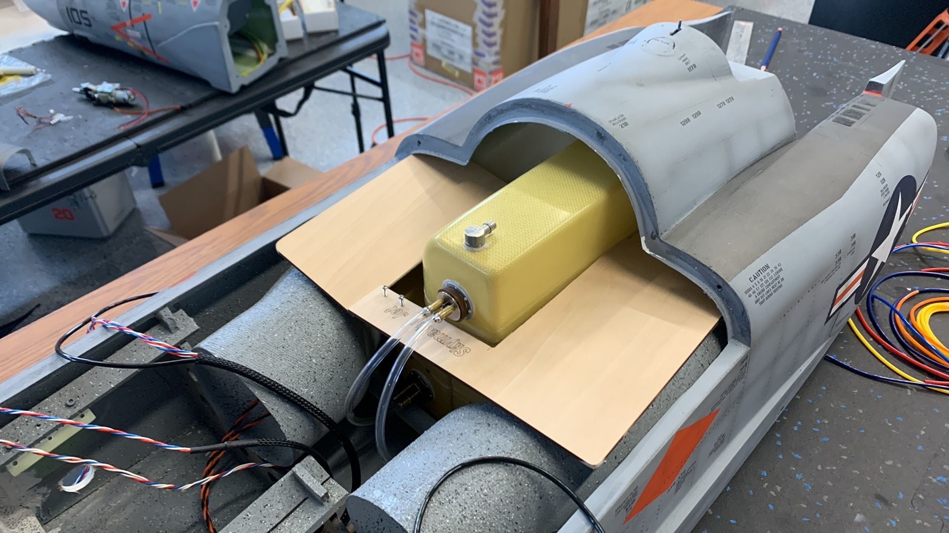
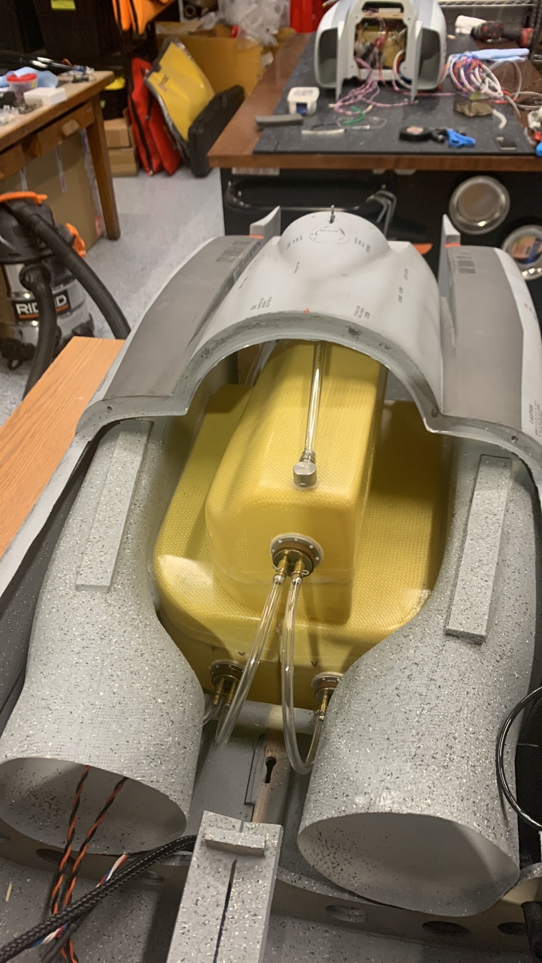
Airtanks installed with blobs of silicone. Tanks were glued together with silicone and Fiberglass tape used to strap it together.
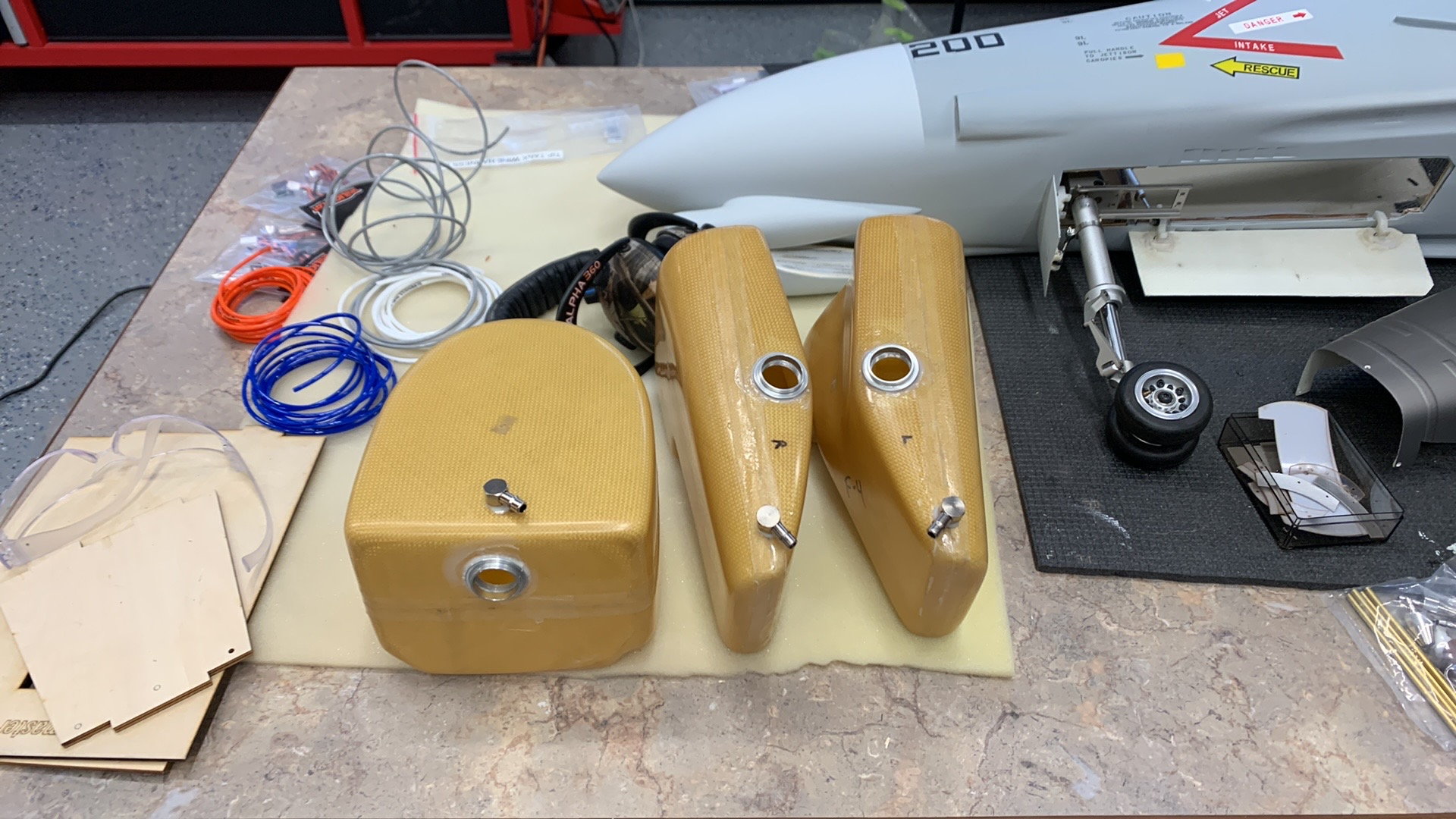
Old aircraft with single engine gets high flow fittings. Engines will be plumbed in series with front tank draining first.
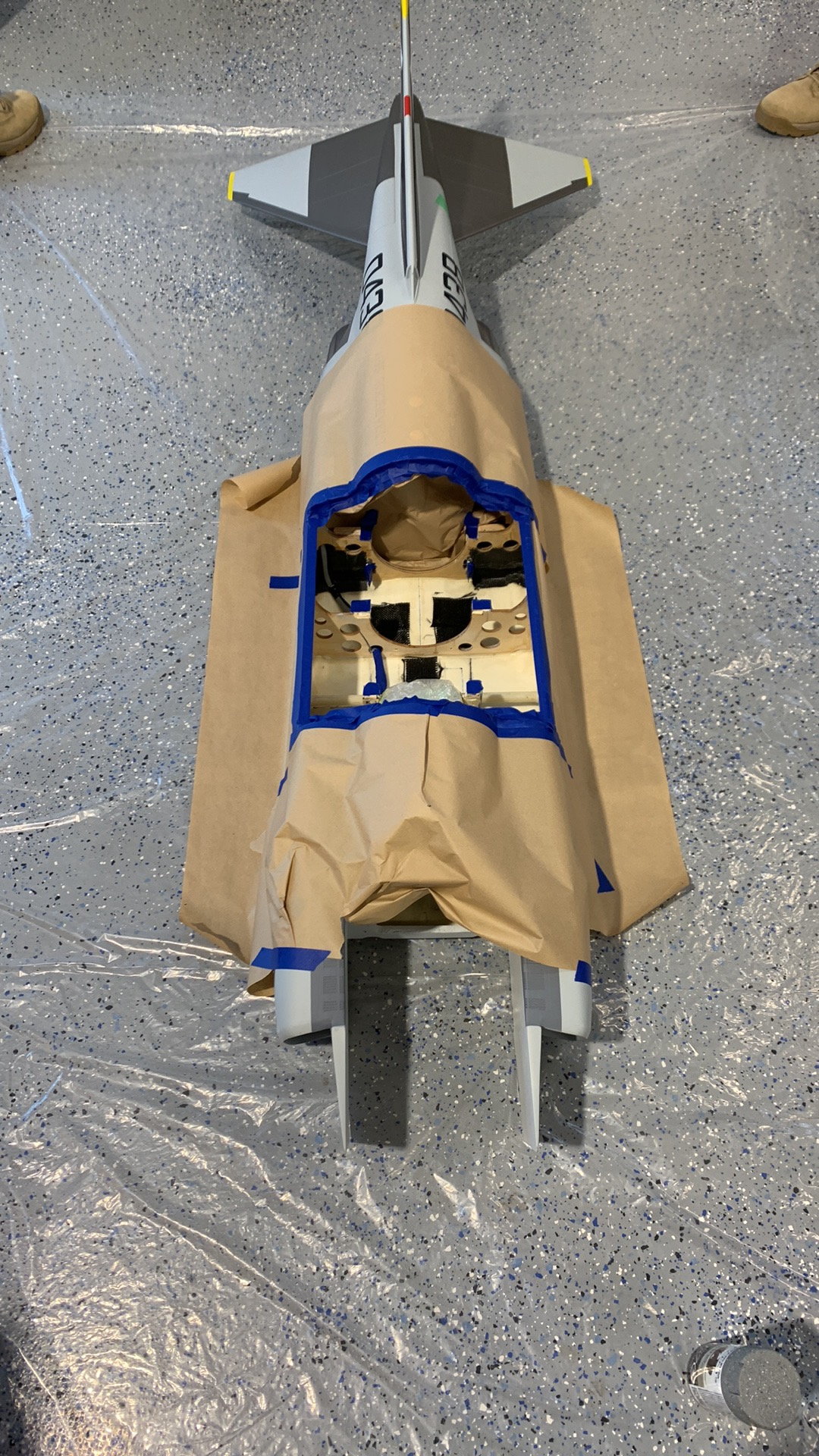
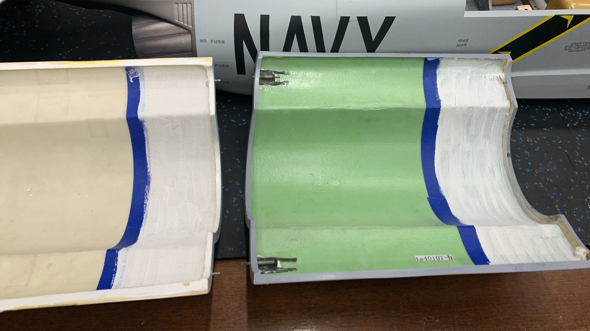
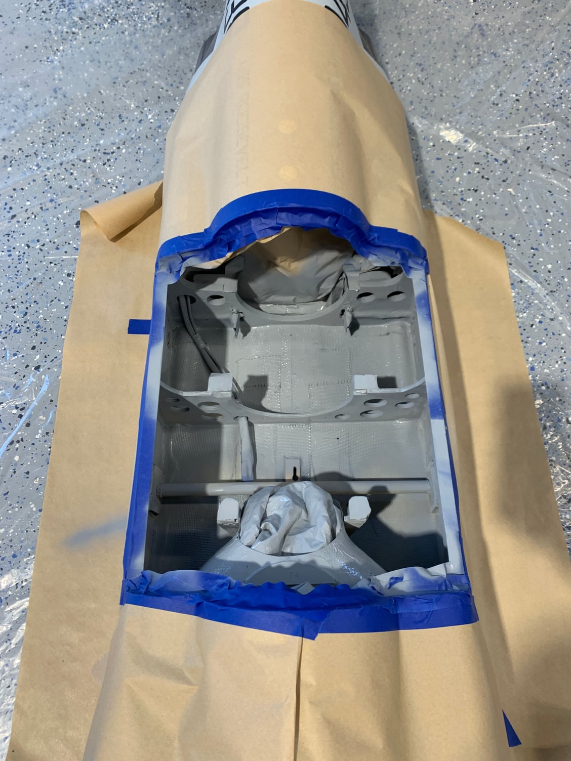
Fuselage interior paint.


tanks glued in place with silicone. Located so if they ever need to come out you can pass fishing line or safety wire through and cut it easily.
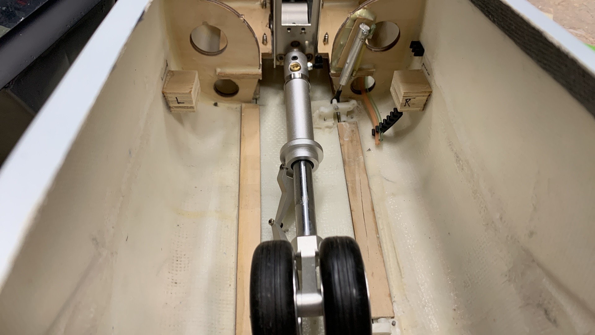
Nose Leg for New F4 Painted.
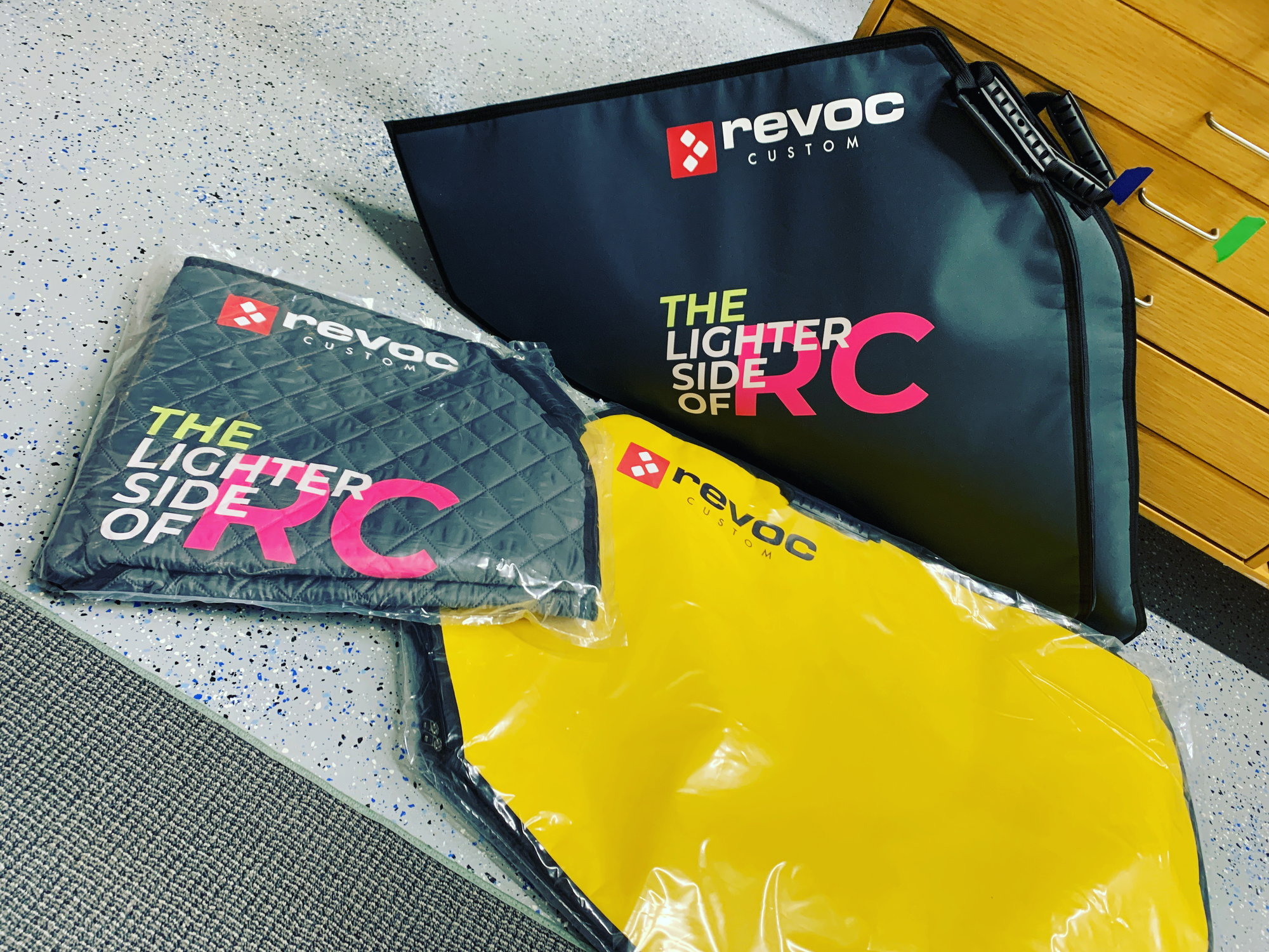
Revoc bag set arrived for the wings. This is the first order of the New Soft line bags.
02-22-2023, 09:27 AM
#546
My Feedback: (1)
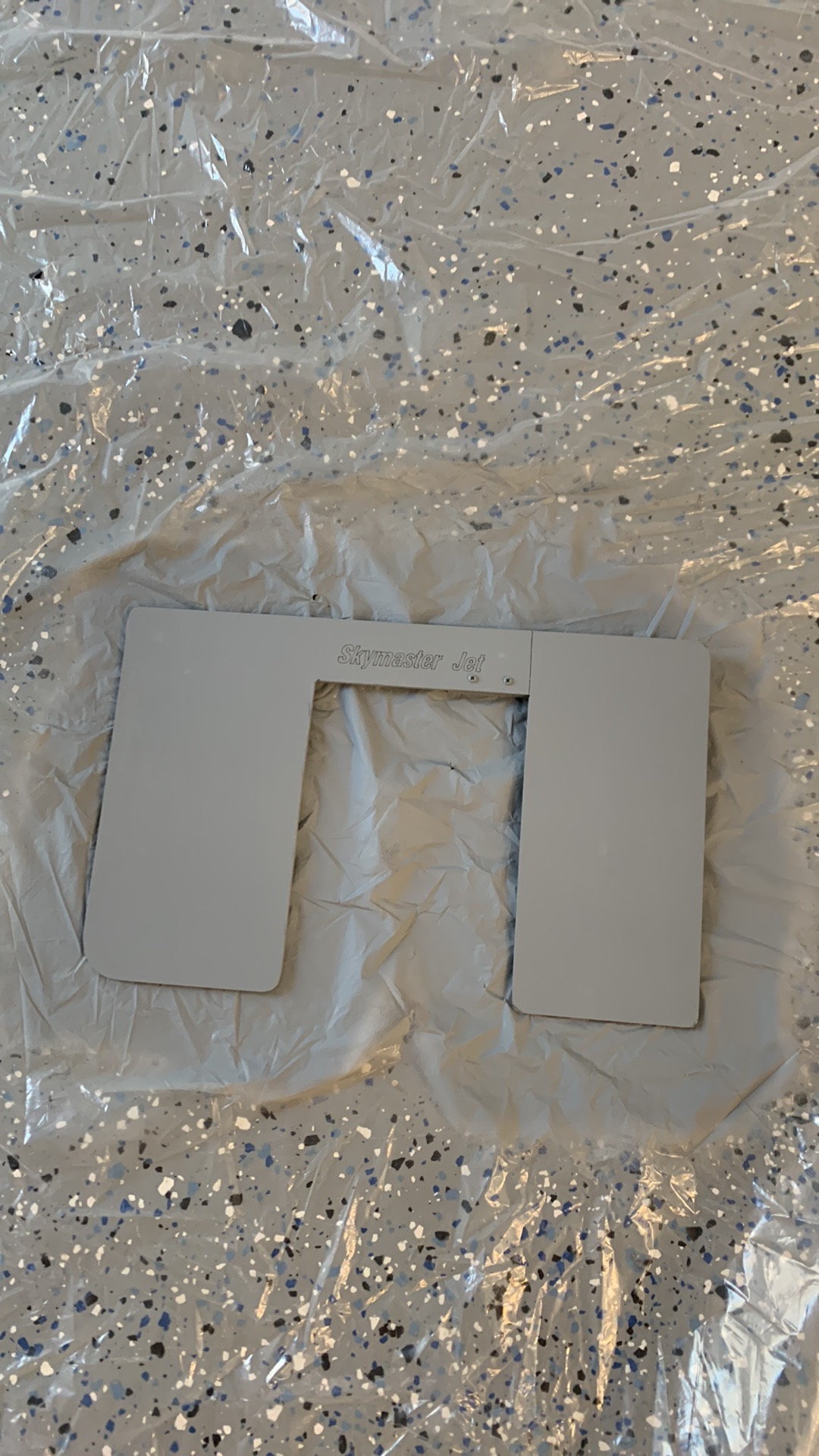
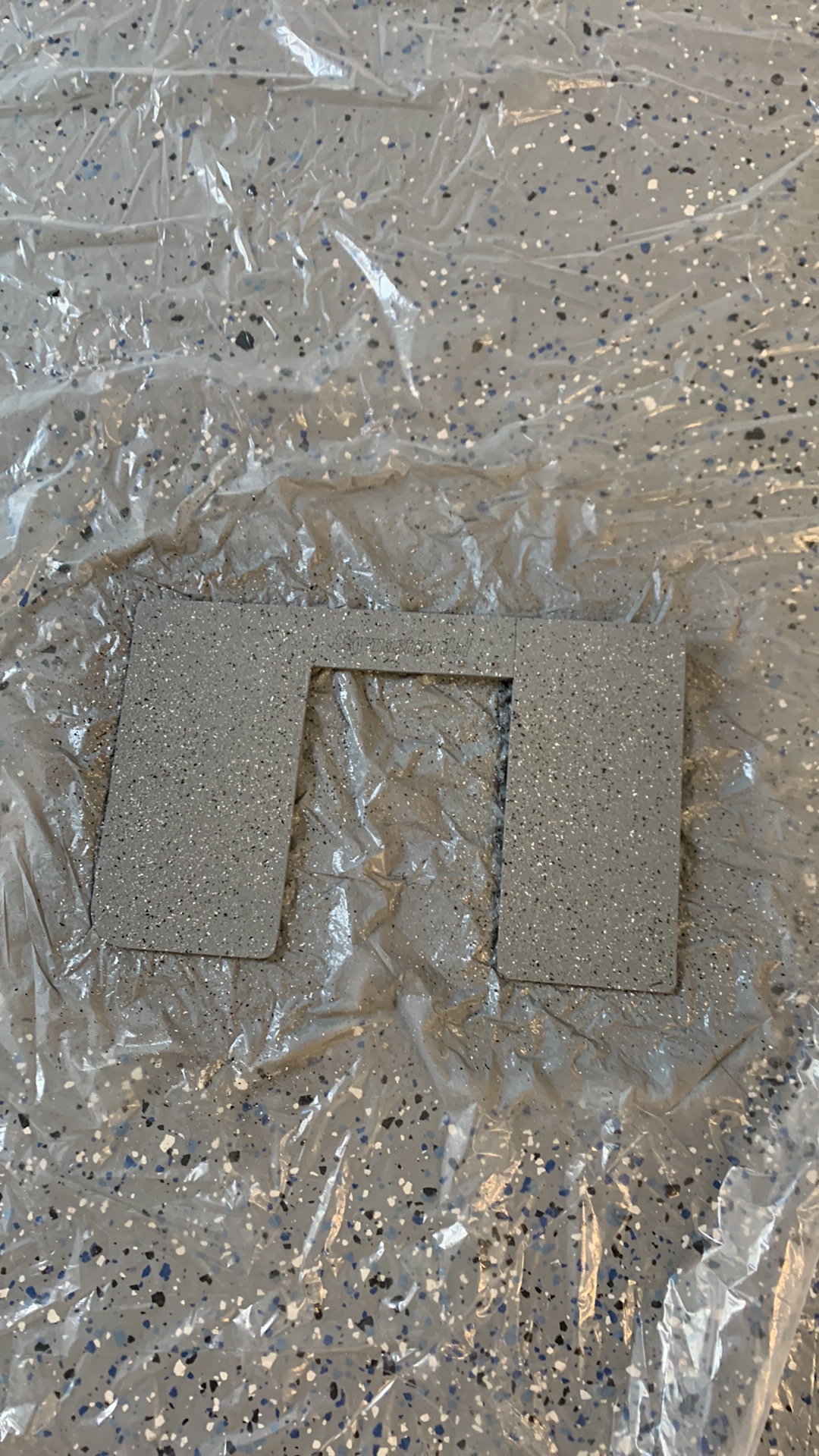
3 layers of BVM Ceramic paint added to hatch above turbines.
Pipe mount made of ply.
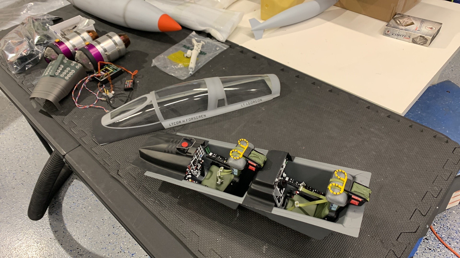
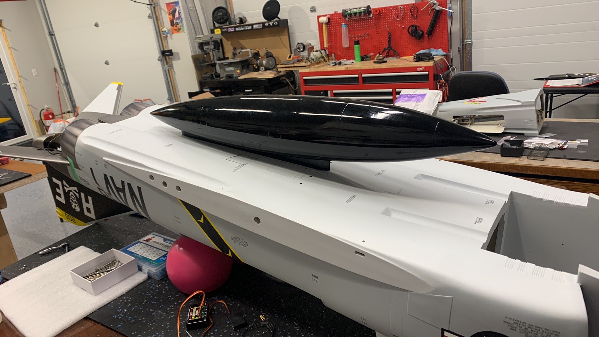
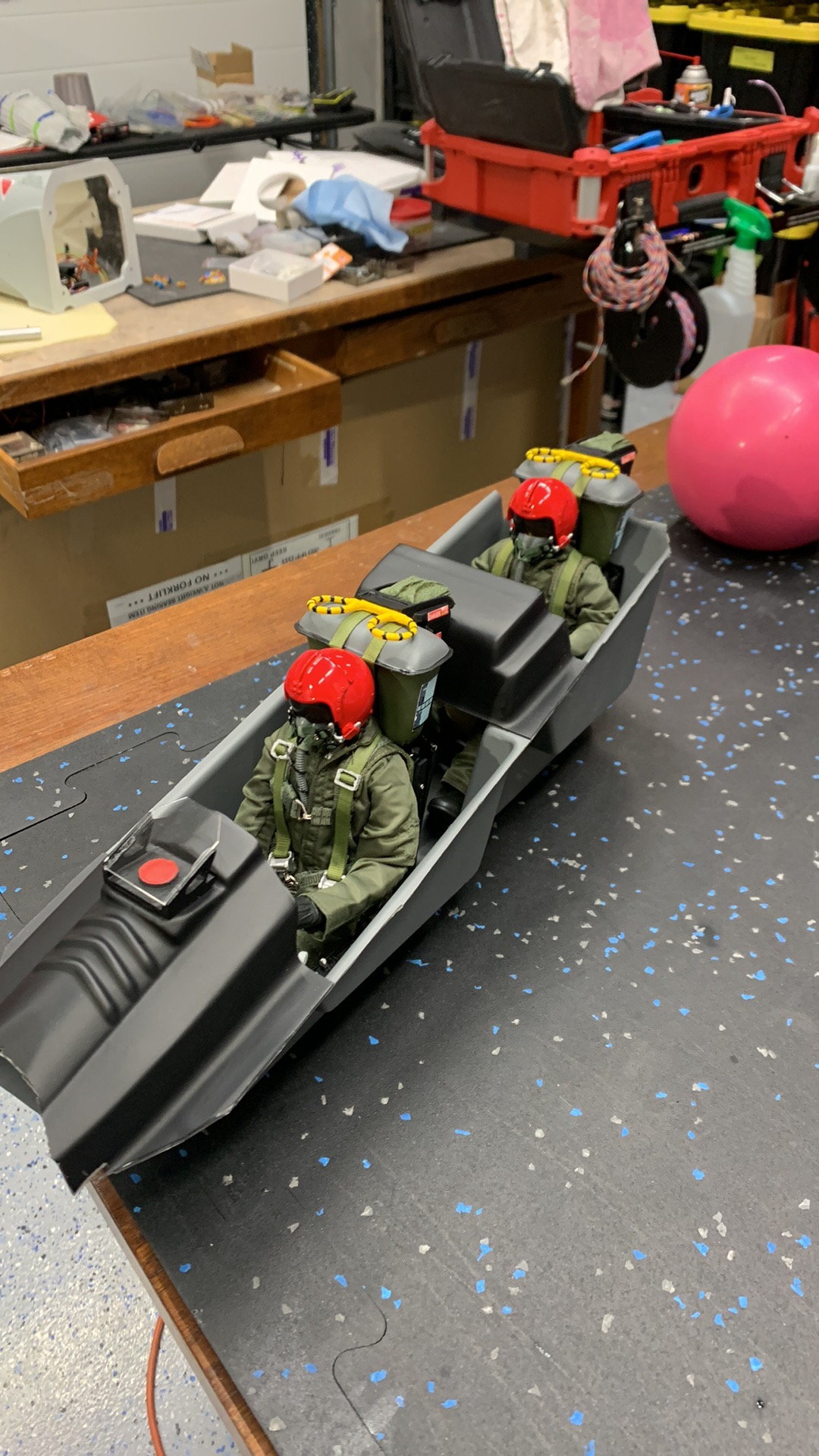
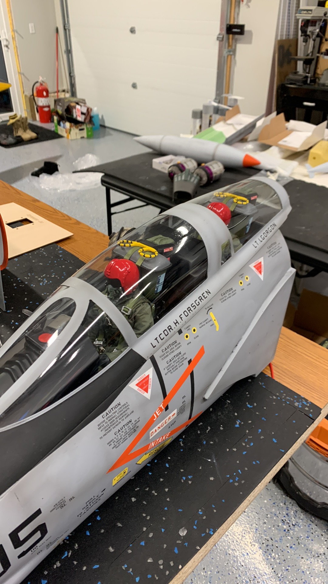
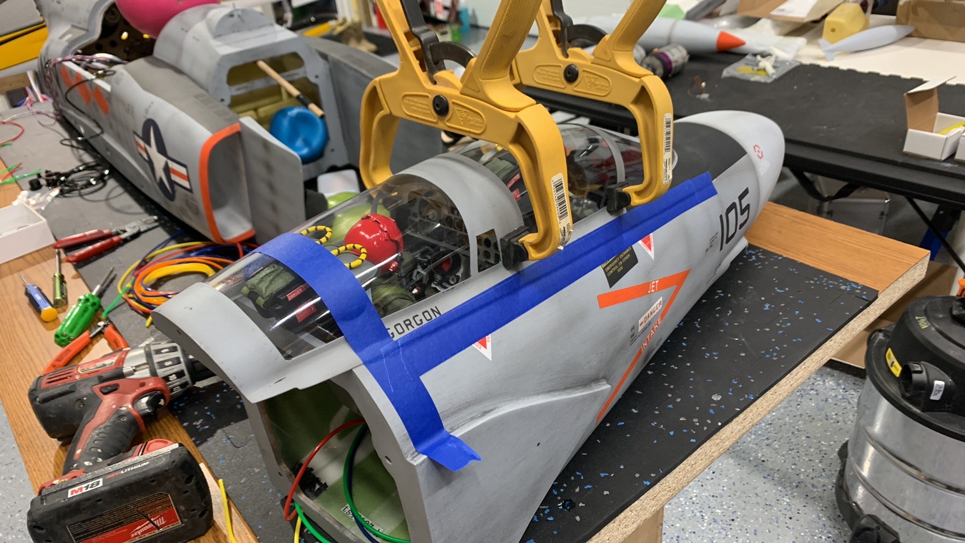
Canopy and cockpit time. The intention was to have the cockpit and pilots installed in the canopy so easy to get in and out in one step. Pull the canopy out and it all comes out in one piece.
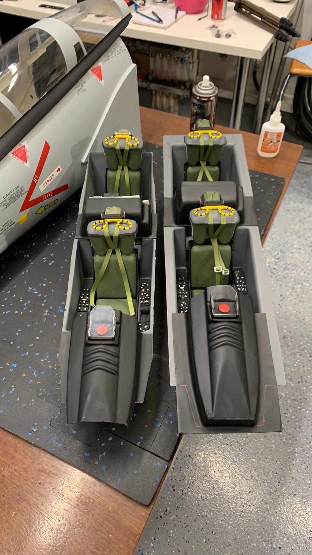
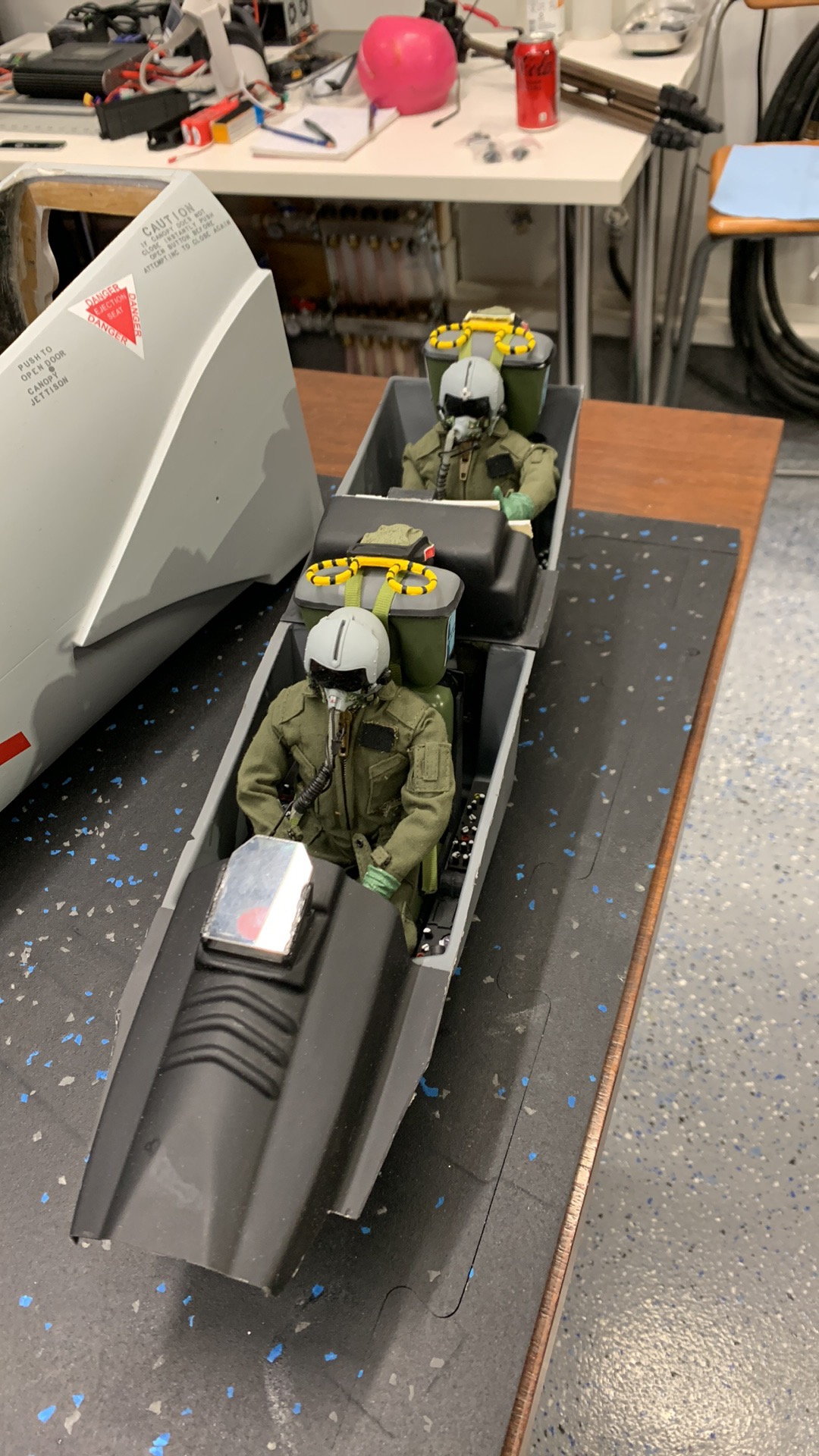
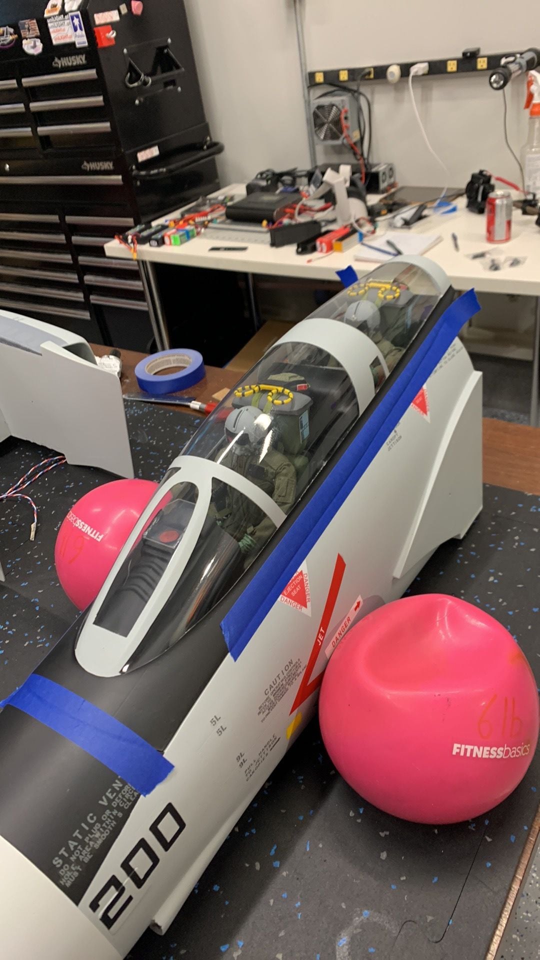
This layout also allowed the canopys to be glued to the cockpit and tighten the sides up. Without it they were too wide and stuck out.
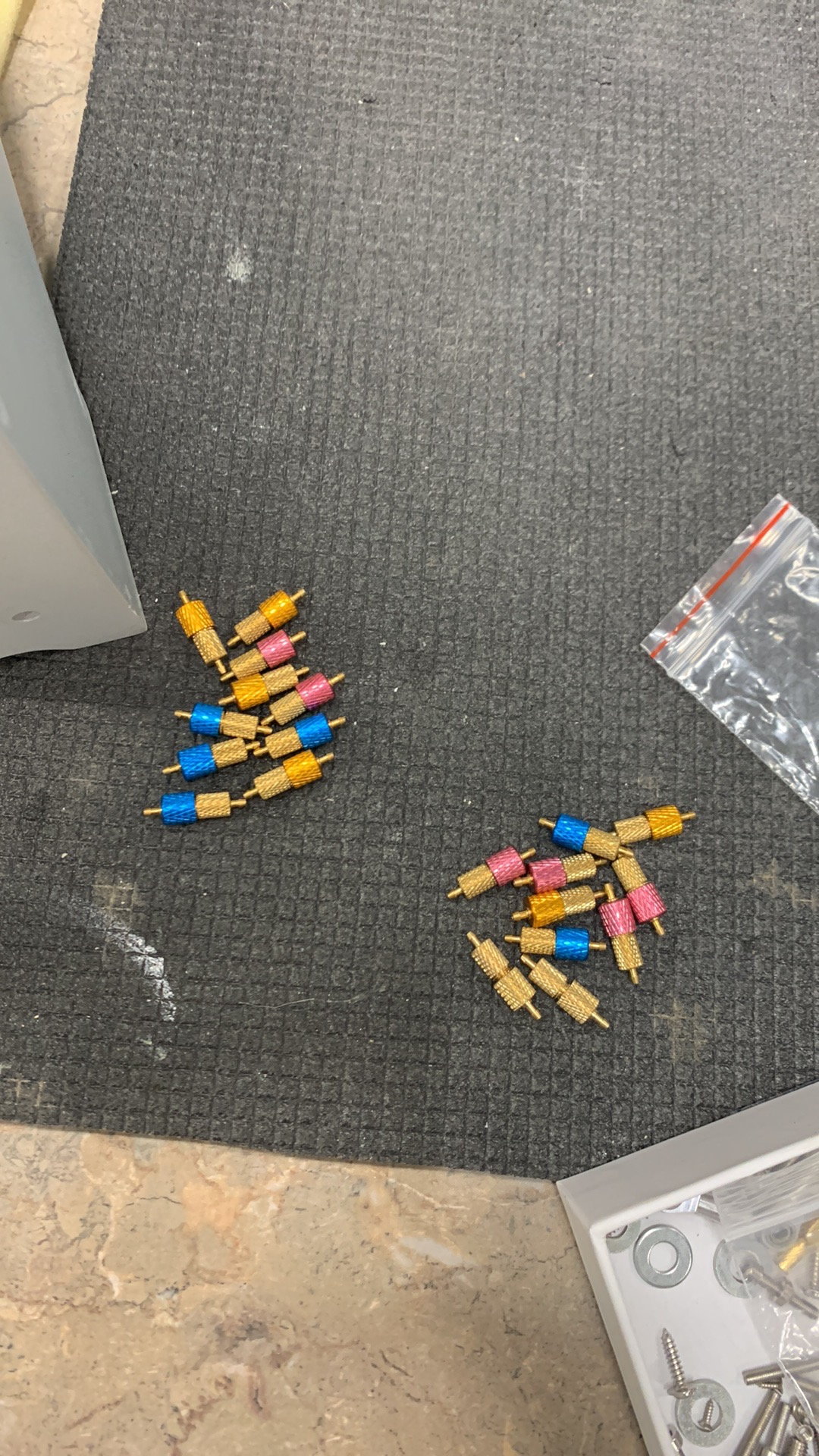
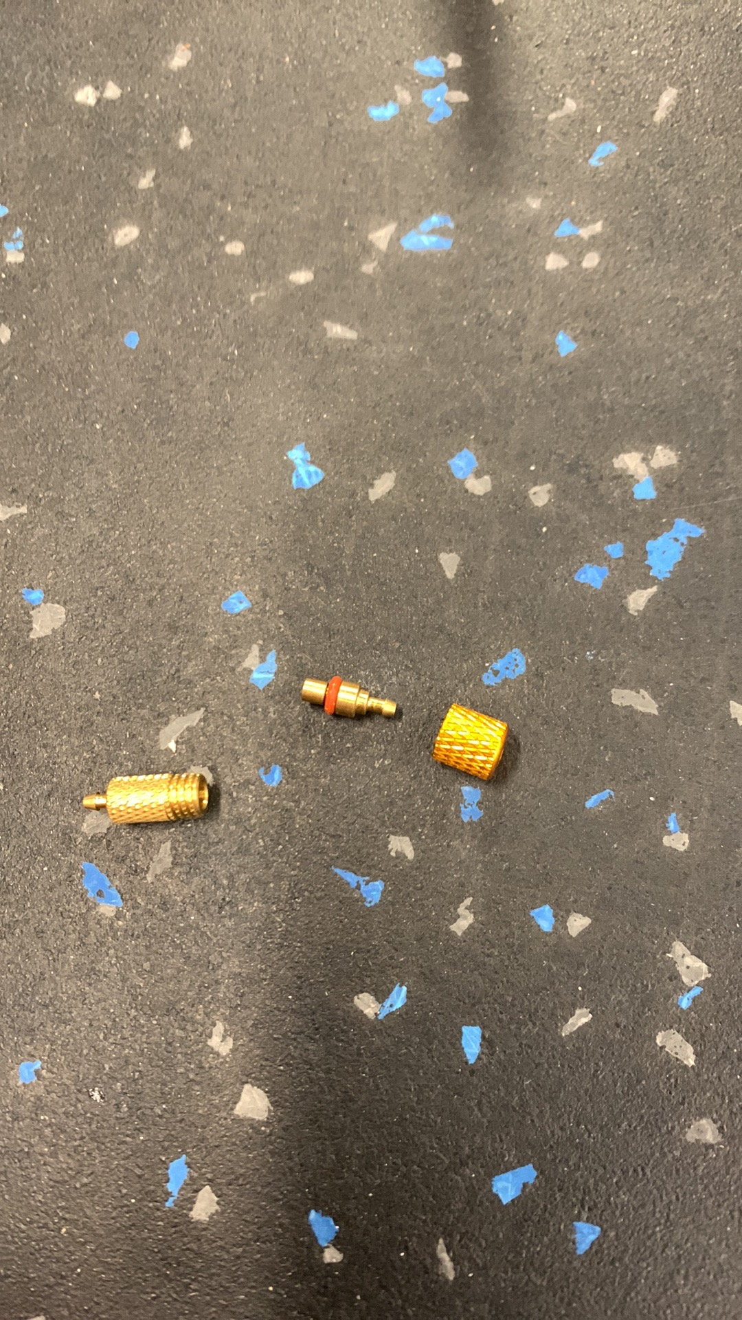
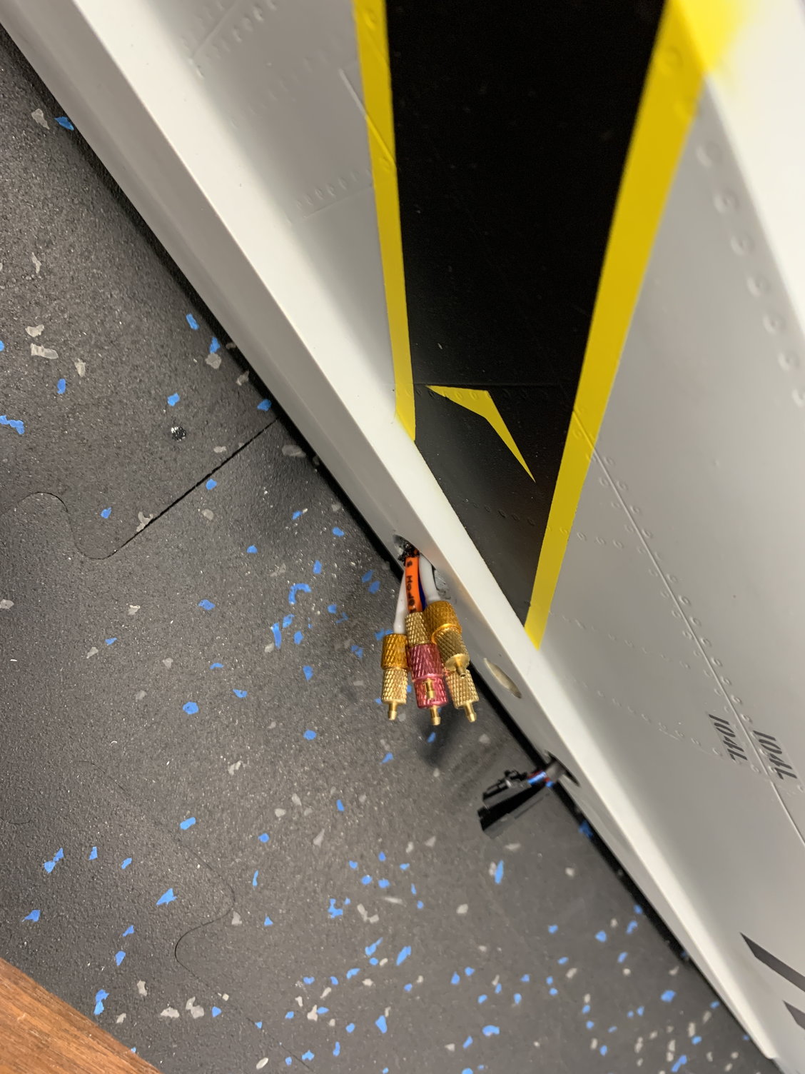
screw in airline connectors for wing joining.
 02-22-2023, 09:31 AM
#548
My Feedback: (1)
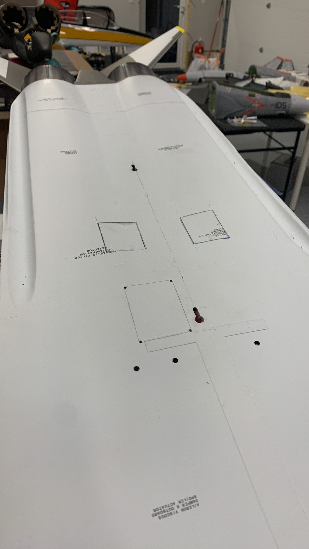
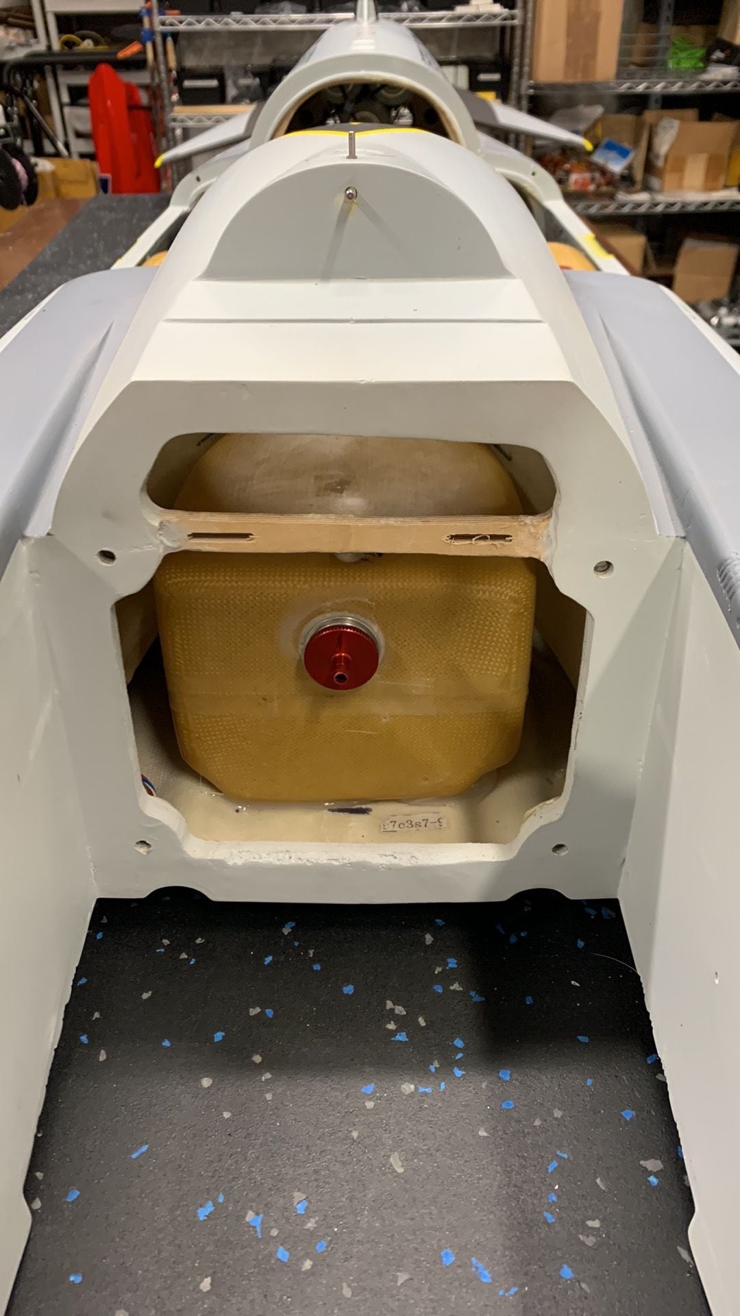
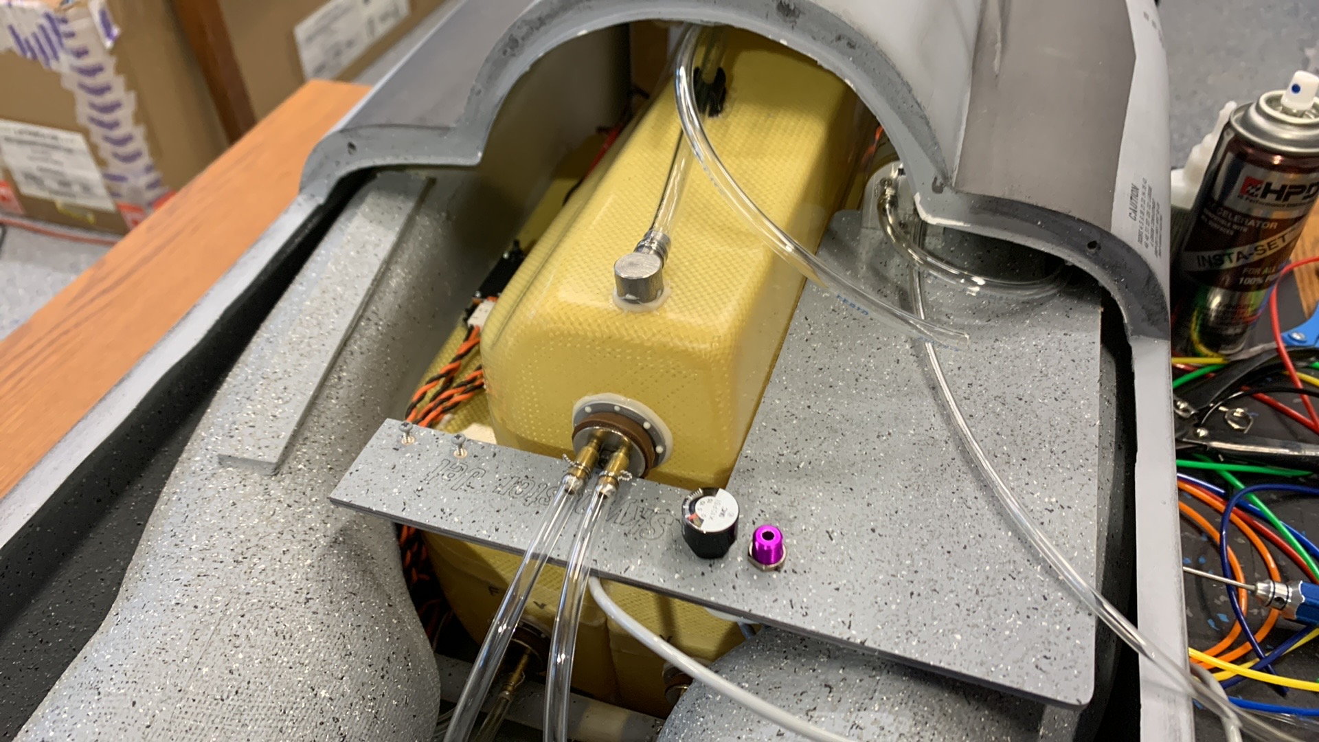
New F4 UAT location
Tanks installed and plumbed.
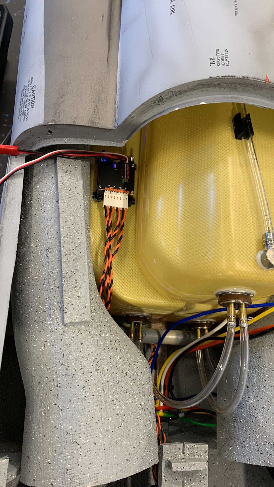
Afterburner light module location.
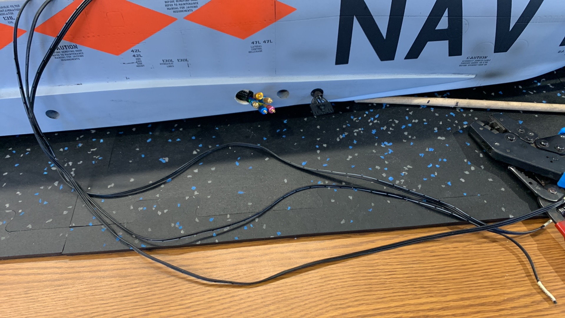
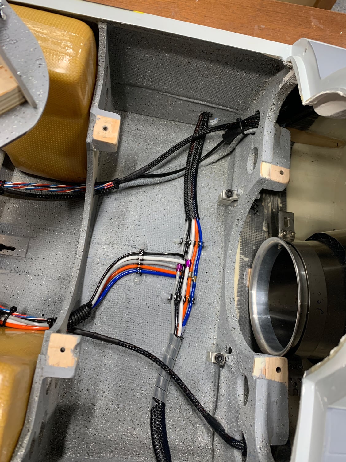
High temp silicone servo wire used for the new aircraft due to location of wires to pipe/turbine. Ashlok 9pin connector used for wing wiring.
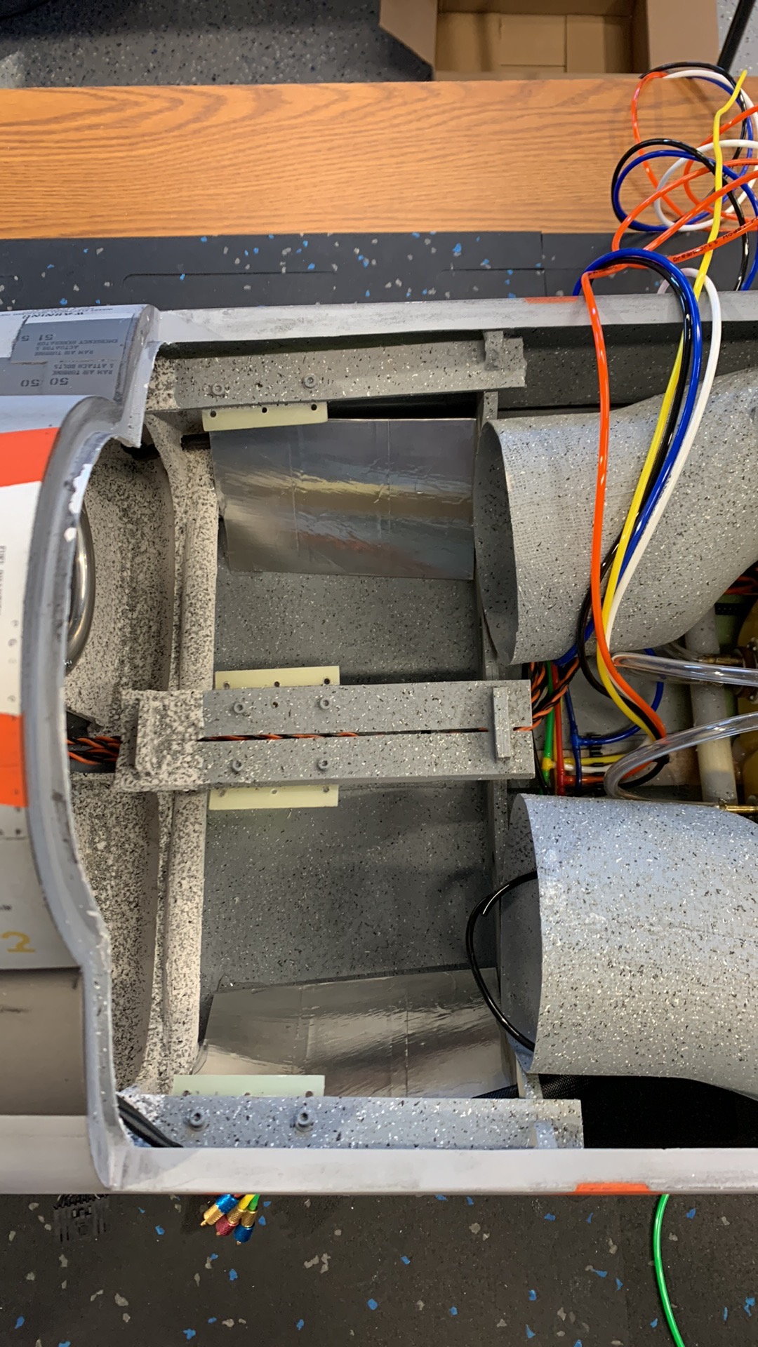
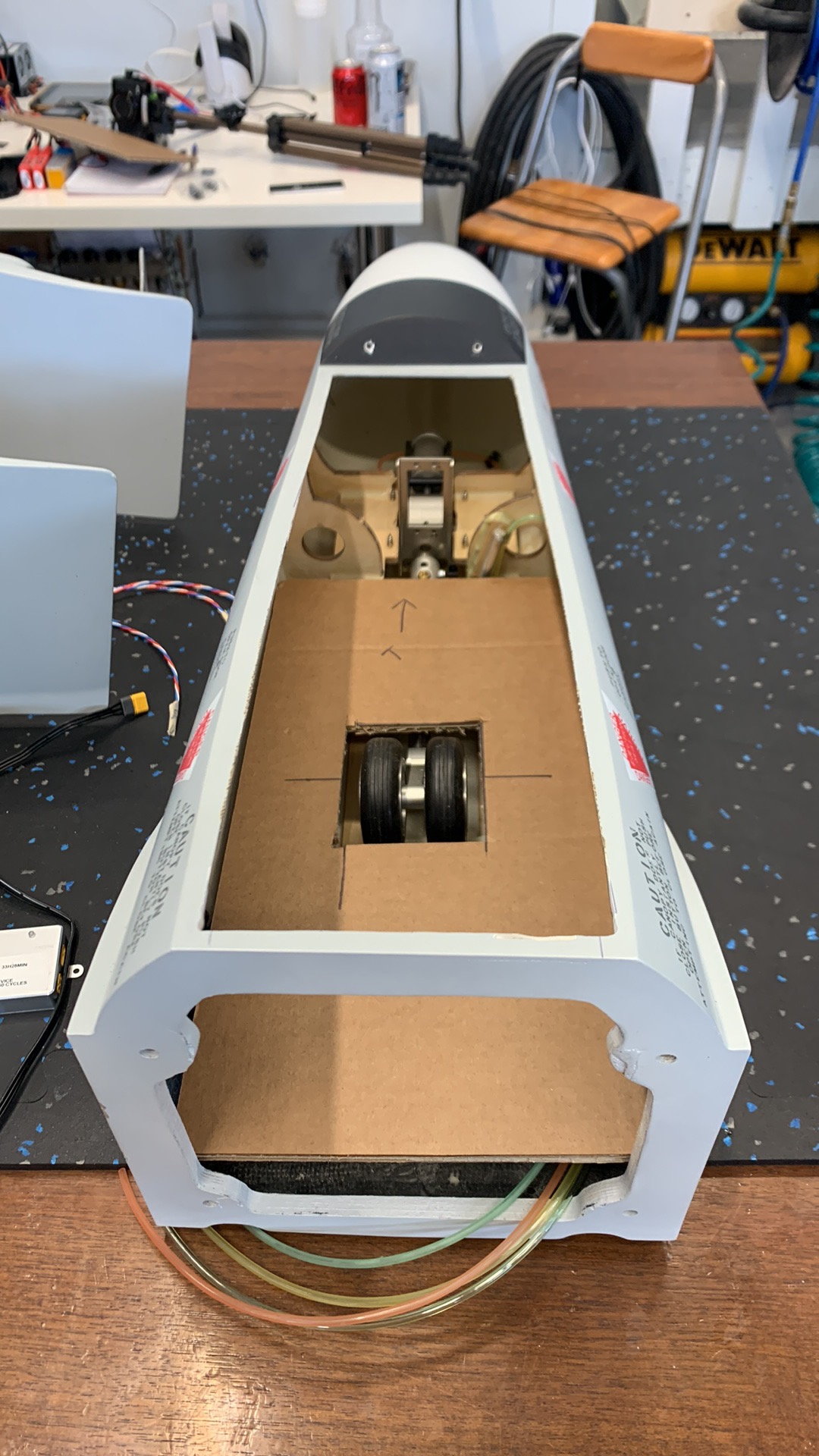
Heat shields installed. Purpose is to protect airlines.
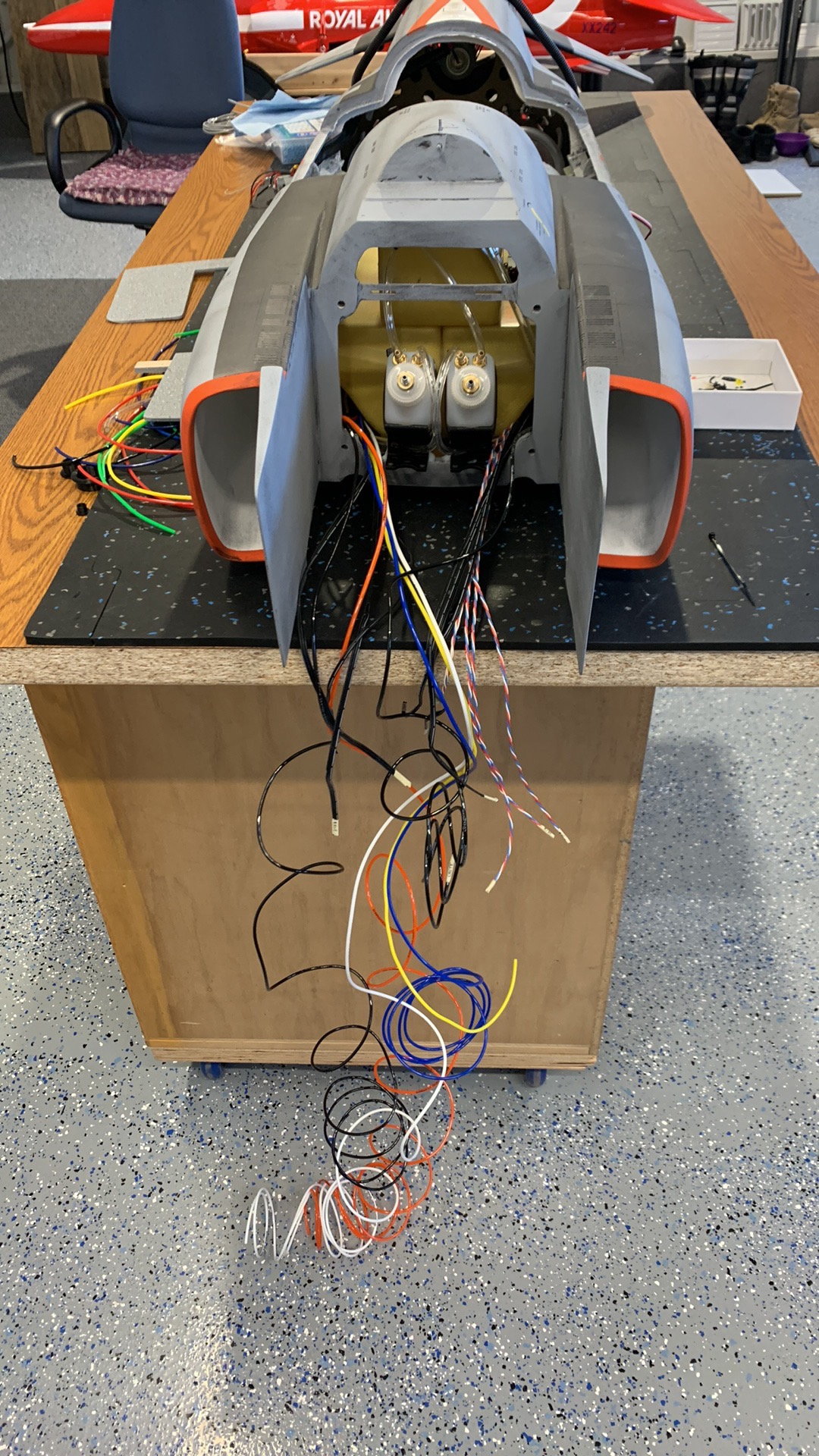
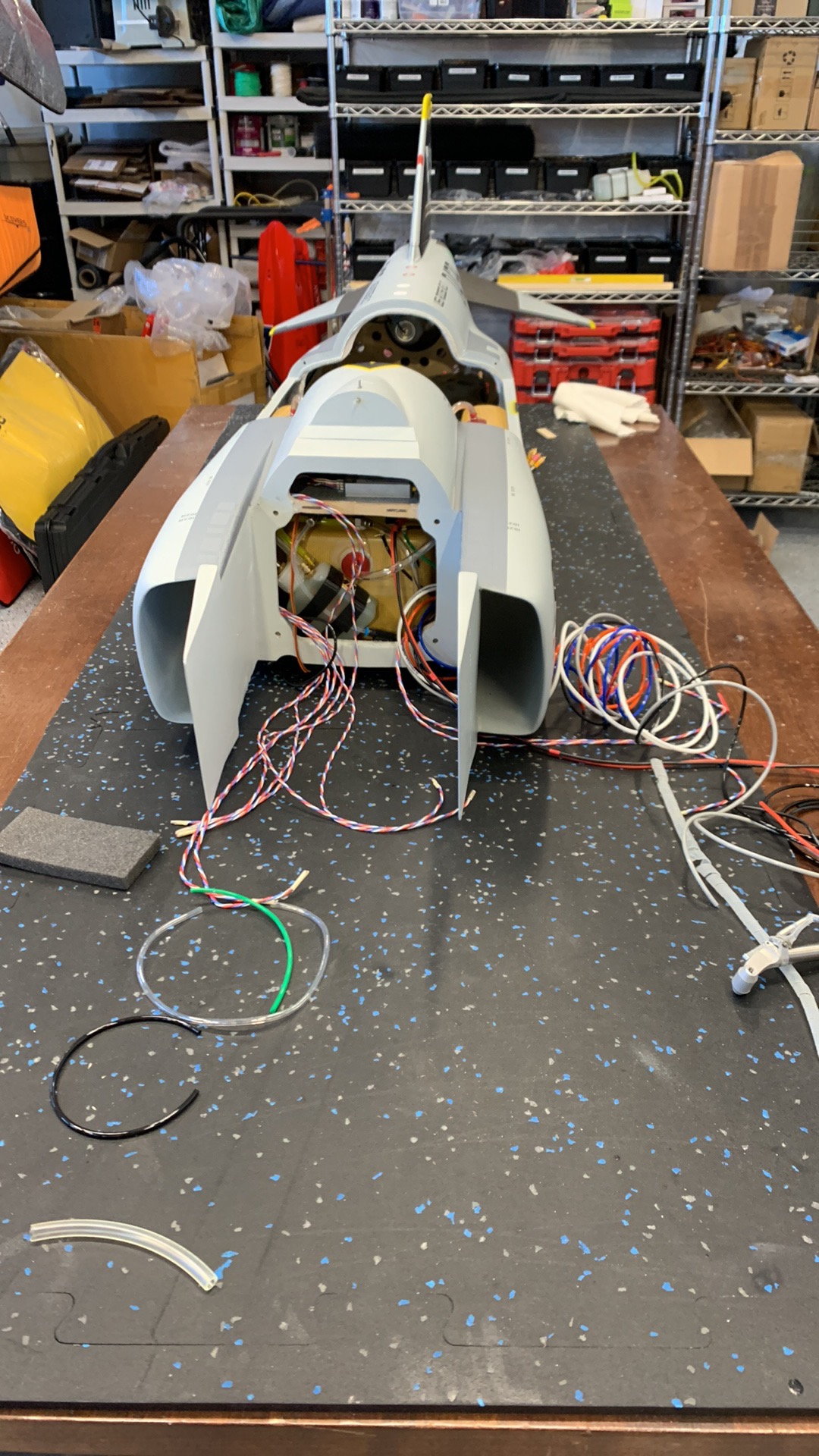
Shots of the mess!
The following users liked this post:
yeahbaby (02-25-2023)