T1 Models Euro Fighter build
 03-19-2018, 06:26 AM
#76

Join Date: Feb 2015
Posts: 208
Likes: 0
Received 0 Likes
on
0 Posts
Congratulations Hot Rod Todd!
Absolutely gorgeous livery!
Please do keep up your posts! They are sooooo extremely helpful.
Thank You!
Mine should be here Wednesday... TNT says so.
Had some problems with HK customs, hence the delay in my delivery.
Also got the full kit, for the 60th DDay Anniversary!
Congrats again! And thanks for your posts and pictures!!!!
Absolutely gorgeous livery!
Please do keep up your posts! They are sooooo extremely helpful.
Thank You!
Mine should be here Wednesday...
TNT says so. Had some problems with HK customs, hence the delay in my delivery.
Also got the full kit, for the 60th DDay Anniversary!
Congrats again! And thanks for your posts and pictures!!!!
 03-19-2018, 06:36 AM
#77


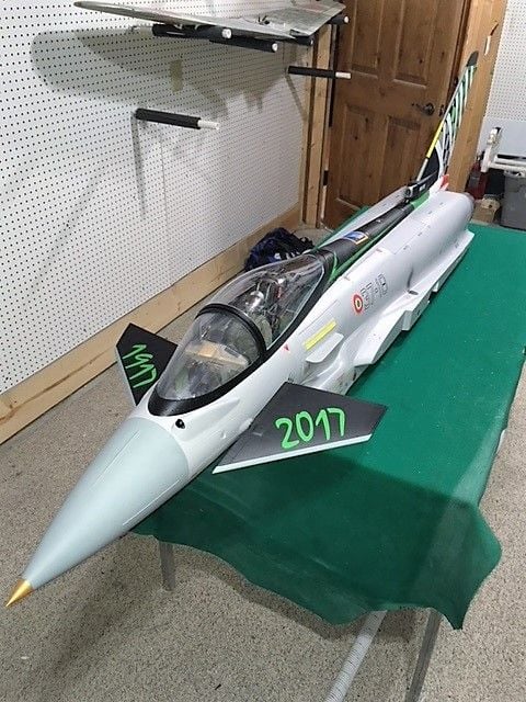
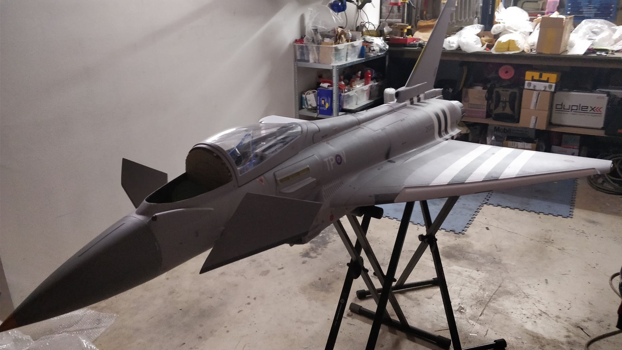
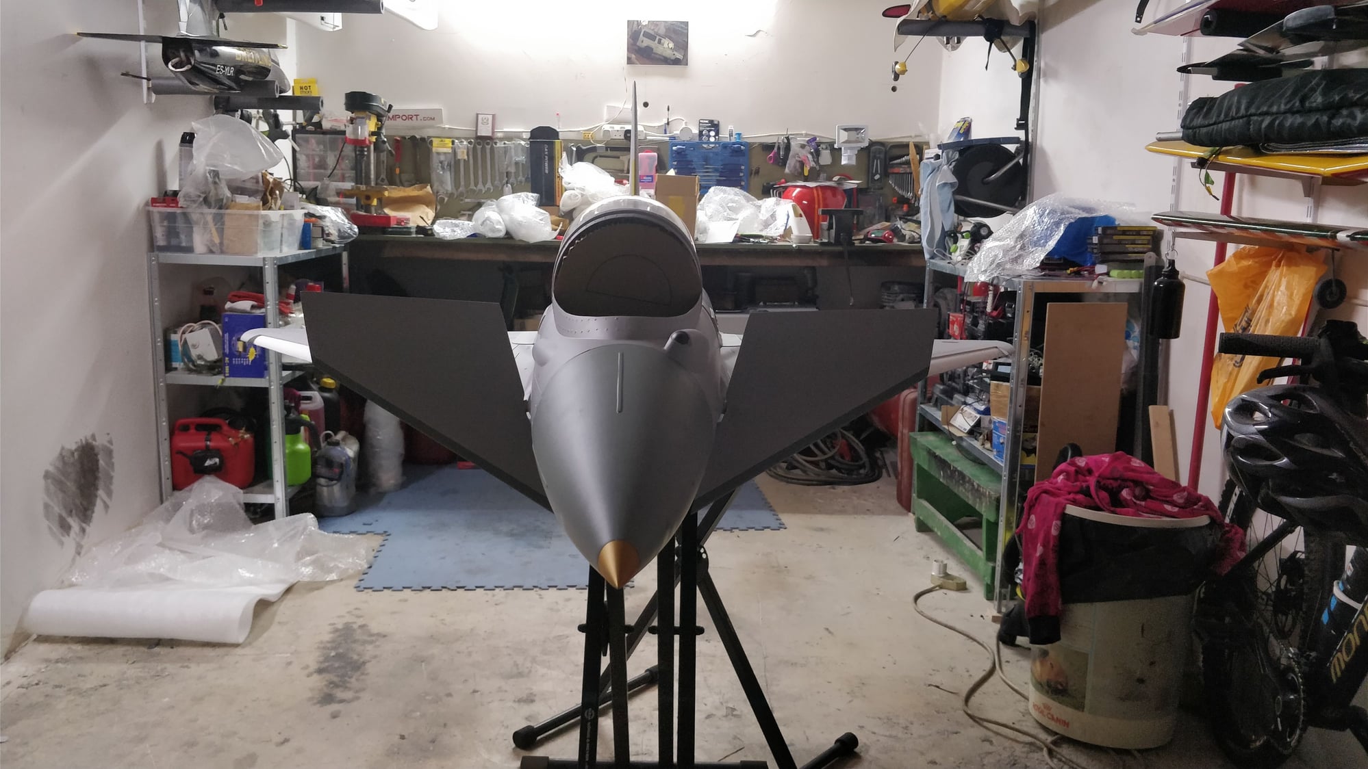
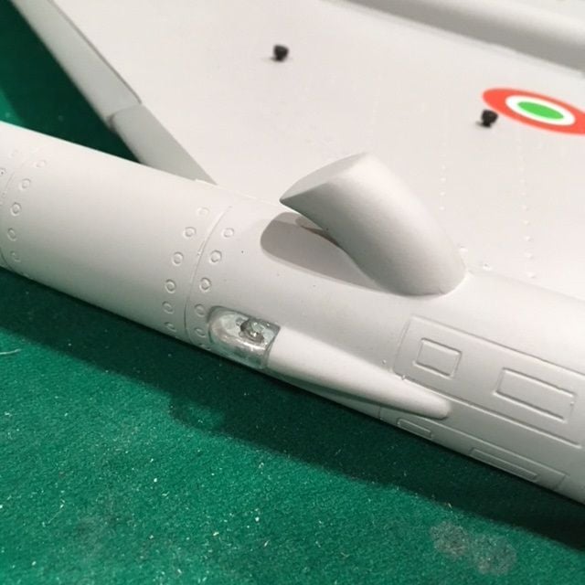
Seems like a good time to take a break and check out how the plane will look. Here's a couple photos of the fuse on my workbench. This scheme has different rudder artwork on either side, and the factory did a nice job of matching it up. They didn't do a very good job on the nomenclature though. They used stickers, and the edges are obvious under the clear coat. Also, they are not accurate for this plane. They used the German/English nomenclature that would be on a German Eurofighter. This plane would have Italian/English text. I can easily peel off the nomenclature stickers, but it leaves a hole in the clearcoat. I'll have to sand that down and touch it up. I plan on matching up the paint to do that. I'll make my own nomenclature using a dry transfer style decal that I can make at home. More to come in a future post. Some people may not care, but I like a nice scale look, and I'll do the extra work to perfect it. I wish I would have told them to leave off all of the stickers, it would have helped speed up the process for me.
Fuse photo showing scheme
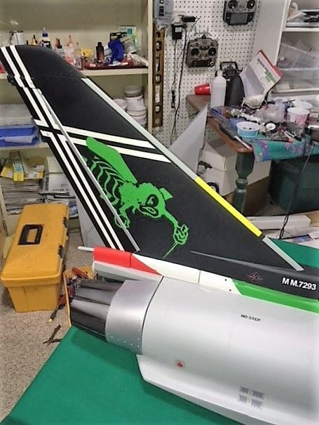
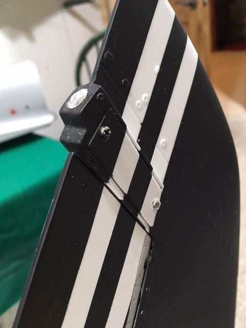
Rudder right side, 1917 squadron insignia
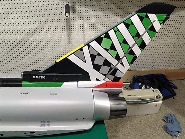
Rudder Left side, 2017 insignia
Fuse photo showing scheme
Rudder right side, 1917 squadron insignia
Rudder Left side, 2017 insignia
03-19-2018, 06:41 AM
#79
The air-brake doesn't take much to get installed, so I thought I'd do it. Two screws hold it on, but it will need some glue on the threads to make sure they don't back out because you can't tighten them down. The air cylinder is spring loaded down, so you only need a one-way valve to push it up. I had to make a hole to allow the air line to clear and enter the fuse. I used some spacers to keep the cylinder centered made from aluminum tube (not provided). Double nut on the screw will keep it in place. Some sanding was needed to make sure the air brake hatch dropped down smoothly. In the end it's a good fit.
Air brake cylinder mount
Air brake cylinder mount
03-19-2018, 07:55 AM
#80
I'll keep them coming. Spring is nearly here, so I plan on getting this thing done in the next few weeks. There's a lot to do.
Next I turned my attention to the landing gear. The doors are pre-hinged and have a tight fit. A little sanding was needed to make sure there was no binding. In the end they fit as well as any I've seen. The main gear fit nicely into the wing and are centered in the wheel wells correctly. It should be no problem to connect the linkage to the wheel cover, but the stock tab is not in the correct location for proper geometry. I made an extension piece out of carbon fiber and glued it using Hysol.
The landing lights were another issue. Getting them to fit around the linkage using the same attachment point was not easy. By rotating the bracket on the light, and counter sinking the screws a bit more than stock, I was able to get clearance. See the photos to check out where they ended up that allows them to retract without interference. Some small spacers and washers helped to allow the ball links to move freely so the door would settle perfectly into the cutout when retracted.
That's all for now. I'll post more as I get it done.
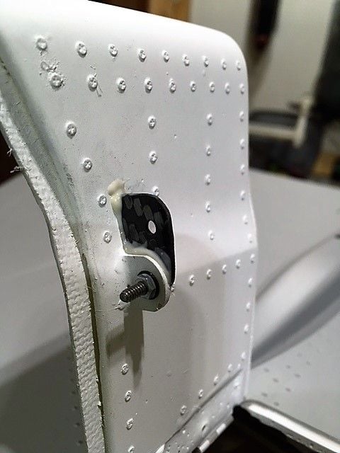
Door modification installed
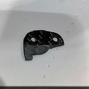
Carbon fiber piece that I made
Left gear leg linkage installed
Right gear leg linkage installed
Next I turned my attention to the landing gear. The doors are pre-hinged and have a tight fit. A little sanding was needed to make sure there was no binding. In the end they fit as well as any I've seen. The main gear fit nicely into the wing and are centered in the wheel wells correctly. It should be no problem to connect the linkage to the wheel cover, but the stock tab is not in the correct location for proper geometry. I made an extension piece out of carbon fiber and glued it using Hysol.
The landing lights were another issue. Getting them to fit around the linkage using the same attachment point was not easy. By rotating the bracket on the light, and counter sinking the screws a bit more than stock, I was able to get clearance. See the photos to check out where they ended up that allows them to retract without interference. Some small spacers and washers helped to allow the ball links to move freely so the door would settle perfectly into the cutout when retracted.
That's all for now. I'll post more as I get it done.
Door modification installed
Carbon fiber piece that I made
Left gear leg linkage installed
Right gear leg linkage installed
 03-21-2018, 05:22 AM
#84
I'll be using my Futaba 18SZ radio and an R7014SB receiver. I was thinking I'd Y-cord some of the wing servos to save channels, but because of the orientation of the servos that's not possible. I'll need a channel for each of the four even though I'm making both surface on each wing move together. If I need more channels than 14 I'll get an SBD-1 S-bus decoder and add some.
Back to the build.
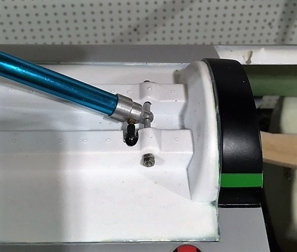
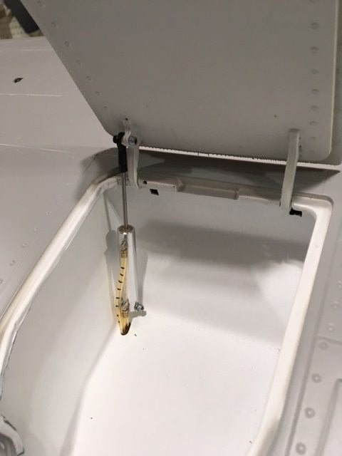
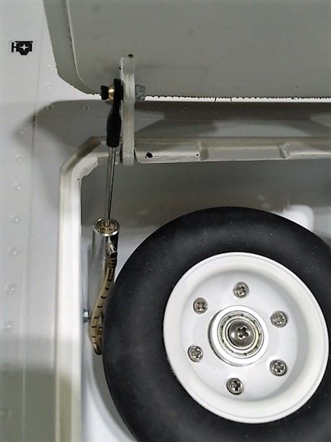
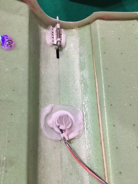
I mounted the door piston in the location provided. I brought the screw through from the inside, locked it with a nut, then used a ny-lock nut on the outside of the piston. It closes all the way, and opens far enough to allow the wheel to retract into the well. You'll notice I put marks on the tubing. There is enough going on inside that I need some organization. The yellow tubing with marks is Door up, without marks door down. I slid the wing on to test the gear retraction, and the wheel fits. It's close to the piston, but it doesn't touch it. Hopefully I don't get any mud on my tires.
I was hoping to have all the wing wiring connections on one Ashlock connector, but that won't be possible. There's no opening inside the wing between where the servo wires exit and the wheel well area. The landing light connection will be with the air connections, and the servo and wingtip lights will be in back of the wing. The photo shows that there's room for the tubing and connections directly in front of the wheel well.
Main door piston attachment
Enough clearance, barely
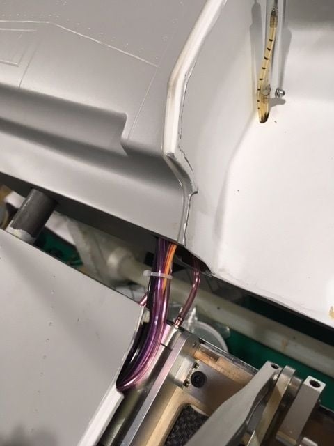
Air and landing light connection location
Back to the build.
I mounted the door piston in the location provided. I brought the screw through from the inside, locked it with a nut, then used a ny-lock nut on the outside of the piston. It closes all the way, and opens far enough to allow the wheel to retract into the well. You'll notice I put marks on the tubing. There is enough going on inside that I need some organization. The yellow tubing with marks is Door up, without marks door down. I slid the wing on to test the gear retraction, and the wheel fits. It's close to the piston, but it doesn't touch it. Hopefully I don't get any mud on my tires.
I was hoping to have all the wing wiring connections on one Ashlock connector, but that won't be possible. There's no opening inside the wing between where the servo wires exit and the wheel well area. The landing light connection will be with the air connections, and the servo and wingtip lights will be in back of the wing. The photo shows that there's room for the tubing and connections directly in front of the wheel well.
Main door piston attachment
Enough clearance, barely
Air and landing light connection location
03-21-2018, 05:32 AM
#85
Join Date: Feb 2015
Posts: 208
Likes: 0
Received 0 Likes
on
0 Posts
To save some chanels, and have best of both worlds, why not use the Xicoy sequencer with min pressure failsafe? Only one channel for gear and doors, one for canopy....and 14 should be ample then..
.
.
03-21-2018, 05:38 AM
#86
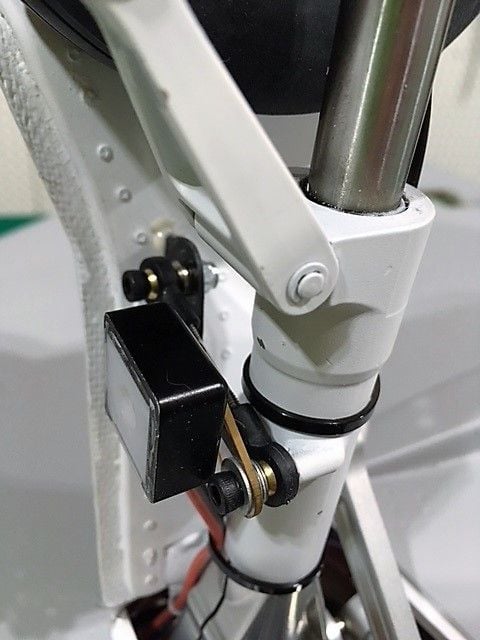
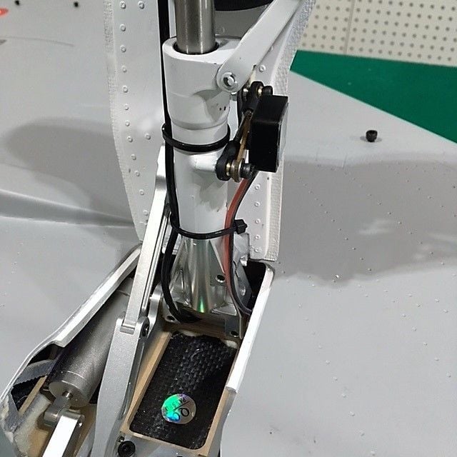
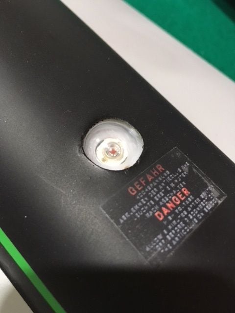
The nosewheel steering has a nice mount that retracts the servo with the gear to keep the linkage easy. Normally I'd like a nice parallelogram where the servo horn is the same width as the horn on the nose strut. In this case, I found that the servo linkage would hit the air piston (that I already mounted for the nosewheel door). I was able to use a smaller horn to get clearance. It has the added benefit of providing a bit more leverage to the steering. By using cables in a pull-pull arrangement I don't have to worry about binding. I used my own hardware, don't expect to get the parts needed for a pull-pull cable in the kit. The steering feels tight, but does not bind up.
I'll mount the nose gear using wood screws. I was thinking about using blind nuts, but that may be a bit too sturdy. If there's an impact it could do more damage than if I use wood screws. The instruction show using machine screws, but there are no nuts in the nose like the ones in the main gear mounts. I think it'll be sturdy enough with the wood screws (that were in the kit).
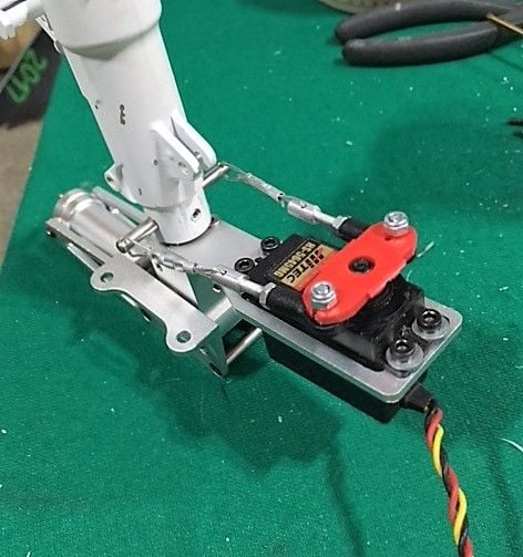
Nose wheel steering
I'll mount the nose gear using wood screws. I was thinking about using blind nuts, but that may be a bit too sturdy. If there's an impact it could do more damage than if I use wood screws. The instruction show using machine screws, but there are no nuts in the nose like the ones in the main gear mounts. I think it'll be sturdy enough with the wood screws (that were in the kit).
Nose wheel steering
03-21-2018, 05:53 AM
#87
Here's what I have so far for channels
4 for the wing surfaces
Canard
Throttle
Rudder
Nose steering
Retract (doors and main)
Air Brake
Wheel Brake
Lights on-off
After Burner
Canopy control (using a sequencer, only one channel needed to drive both valves)
That's 14
I'd also like a channel for landing light control that I can mix to the retract switch so the landing lights don't stay on all the time. That will use a simple electronic switch.
If I get a gyro, that's another channel to control it.
03-22-2018, 09:59 PM
#88
Join Date: Feb 2015
Posts: 208
Likes: 0
Received 0 Likes
on
0 Posts
https://photos.app.goo.gl/j9XxT6Z5Fva8TlCy2
Too many to post!
Only missing the light kit and smoke tank... I am sure that they will be sent aside since they where left out in then packing process!
Really really beautiful finish!
Thumbs up Mr. Kim! And a great thank you to Jean-Marc of Kingtech Turbines of Luxembourg for his help and patience to place the order!
 03-23-2018, 04:44 AM
#92
Looks good George. Glad to see you got it with no damage.
I got working on installing the servos in the wings. As mentioned before, there some work to do to hog out the openings to match the full size servos. You have to be careful to not go through the wing, the pockets are shallow. I used epoxy to put the spacers in, figured it would add some strength. I found some 3/4" screws that would give more bite, and the counter sunk heads worked good to cut down on the space. It's a tight fit under the covers, so you have to keep that in mind as you fit the servos into the pockets. I only used three screws per servo, but with the screws I used and considering how tight they jam into the pockets, I'm very happy with how sturdy the mount is.
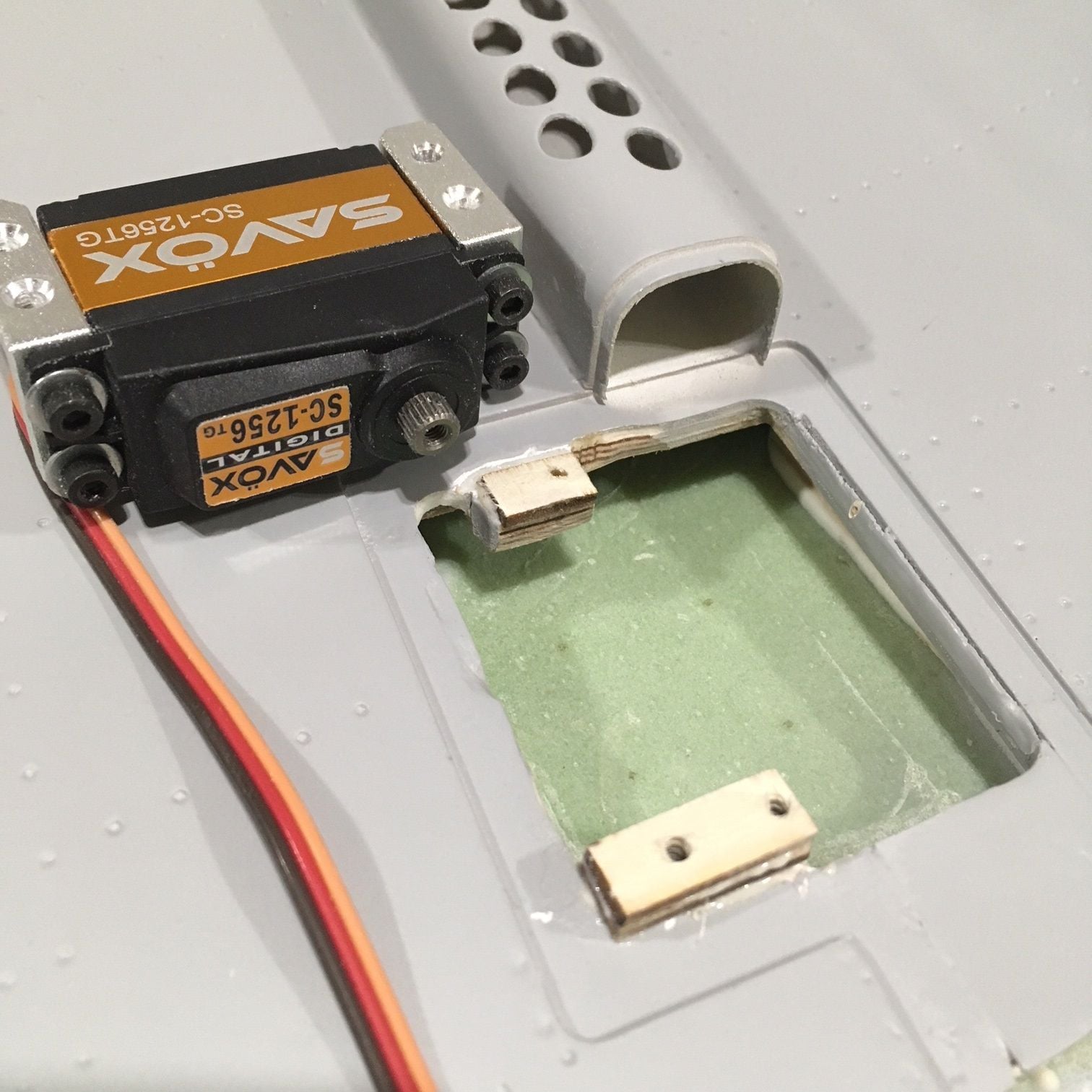
Servo ready to install in modified opening
There is a string though the wing to route the wire from the wing light, and a tube running though the wing for that string. Nothing to help with the servo wires though, and the tube for the lighting wire just gets in the way. I found that I could use a curved wire to route it though and grab my servo wire.
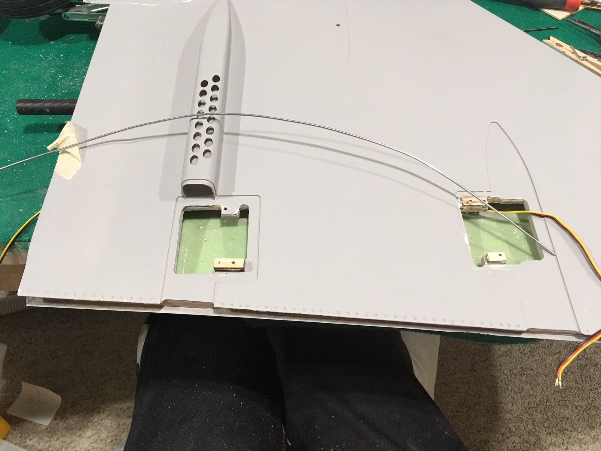
Use a curved wire to route to the outside servo and grab the wire
I got working on installing the servos in the wings. As mentioned before, there some work to do to hog out the openings to match the full size servos. You have to be careful to not go through the wing, the pockets are shallow. I used epoxy to put the spacers in, figured it would add some strength. I found some 3/4" screws that would give more bite, and the counter sunk heads worked good to cut down on the space. It's a tight fit under the covers, so you have to keep that in mind as you fit the servos into the pockets. I only used three screws per servo, but with the screws I used and considering how tight they jam into the pockets, I'm very happy with how sturdy the mount is.
Servo ready to install in modified opening
There is a string though the wing to route the wire from the wing light, and a tube running though the wing for that string. Nothing to help with the servo wires though, and the tube for the lighting wire just gets in the way. I found that I could use a curved wire to route it though and grab my servo wire.
Use a curved wire to route to the outside servo and grab the wire
03-23-2018, 04:55 AM
#93
I glued in the control surfaces using Hysol. Prior to gluing I went in and made sure I had good clearance for the hinge. Not sure how much throw I'll need with the elevator-aileron mix. Put some vaseline on the hinge joints prior to gluing. They fit tight and lined up well. The factory did a good job on the hinges. Once I ran the wires through I mounted the servos. I used some dubro ends on the stock rods. Because the horns on the surfaces are fairly short I was able to use a short arm on the servo. They had to be cut down a bit to clear the covers. I don't have the covers pictured, but it takes some work to get them to fit. A bit of hogging out to make sure they clear the servo mounts. As you can see on the outer servo below I also had to take some edges off of the mounts to get the cover to clear. The material the covers are made from is a bit brittle. Be careful when drilling. I had to repair a couple of the tabs that broke while I was putting the screw holes in them. The provided small screws are not the greatest. I snapped one off by making the pilot hole too small.
In the end I'm happy with the mounts and the travel the servos provide.
Lots more to come this weekend. We're getting some snow, so I'll be busy working on the Typhoon in the Blizzard.
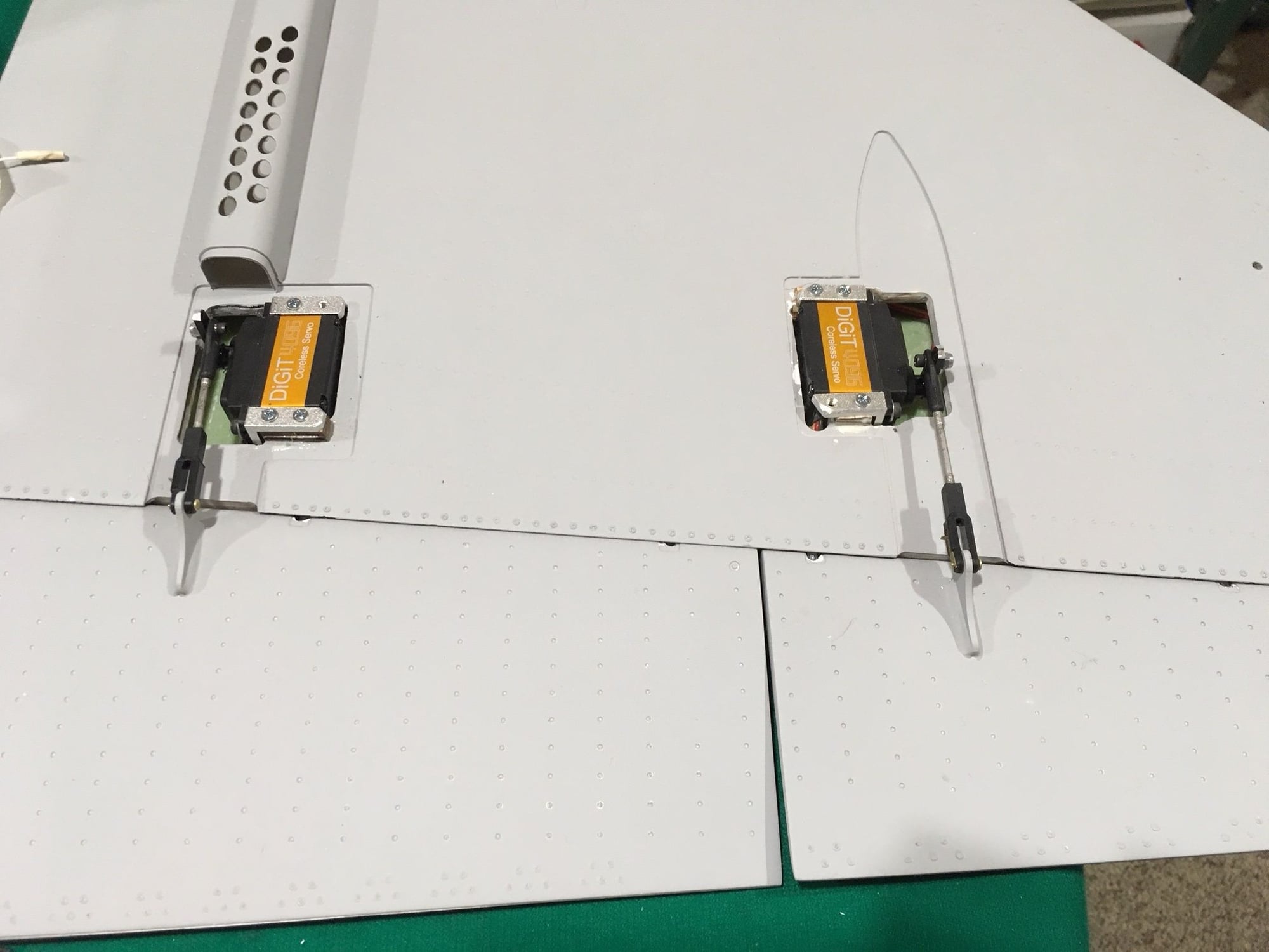
Servos mounted in the wing
In the end I'm happy with the mounts and the travel the servos provide.
Lots more to come this weekend. We're getting some snow, so I'll be busy working on the Typhoon in the Blizzard.
Servos mounted in the wing
03-23-2018, 11:05 AM
#94
Join Date: Feb 2015
Posts: 208
Likes: 0
Received 0 Likes
on
0 Posts
Thank you for the lovely informative pictures! You make the build look sooooo easy! Thanks for the info!
What tank setup are you using? 2 tanks plus smoke? I ordered a smoke tank to use as a saddle tank... But is still in China
With regards to the factory installed lights... Mine was ordered with factory installed lights, bit came with none, not even the lights. Tubes seem to be in the wing and tail for the lights, but no strings or anything in them. Do you have any pictures of the lighting as is installed by the factory? I will have to retro fit mine when I get my kit from Kim... Any pictures of the placement would be appreciated!
I hope the missing light kit and tank don't take to long to get to me.
Thanks again!
George
03-23-2018, 11:21 AM
#95
I'll be using the two tanks in series, and one bubble-free tank. Not sure where the smoke tank would fit. The lights on mine came installed. If you have to do it yourself it will be some extra work. It shouldn't be too hard to run the wire through the wing as long as there's a route. It's a straight shot. Next time I shoot some progress photos I'll take some of the lights as they came on my plane. They should take some money off, if you ordered lights Installed, but got the kit. (you may want to ask AFTER you get the light kit).
Glued my ends on the wings and the leading edge slats. I used Hysol (as usual) after sanding through the paint. They should be permanent.
Glued my ends on the wings and the leading edge slats. I used Hysol (as usual) after sanding through the paint. They should be permanent.
03-24-2018, 02:12 AM
#97
Join Date: Feb 2015
Posts: 208
Likes: 0
Received 0 Likes
on
0 Posts
Finalising my shopping list.
What air bottles did you opt for?
Did yours come with air tanks with the kit?
I was planning to fit three cans, with the larger for the doors, the other two for gear doors and brakes, and canopy and speed brake separately.
Xicoy valves with sequencer x2
The Xicoy have the emergency deployment feature, so one for the system on the doors, and one on the gears per se.
George
03-24-2018, 06:45 AM
#98
I'll use a Robart large tank for the mains and doors, and two medium tanks (not sure the brand but about the size of a medium Robart). One for the Brakes & Airbrake, and the other for the canopy. I believe the large can will fit in the rear compartment, kind of to the side of the turbine. The two smaller tanks can fit underneath the fuel tanks. The Xicoy would be nice, but I'm using what I have.
03-26-2018, 05:04 AM
#99
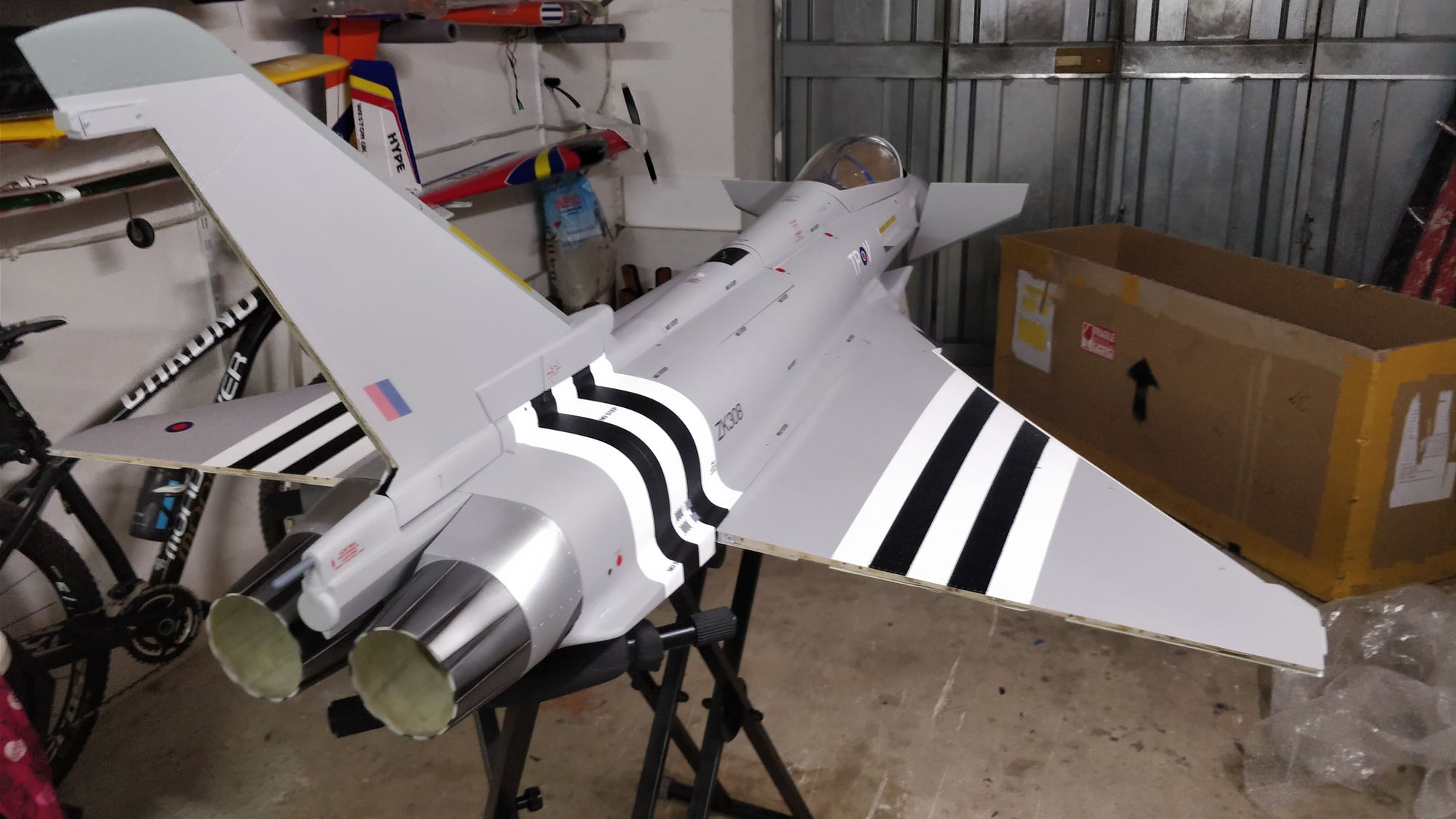
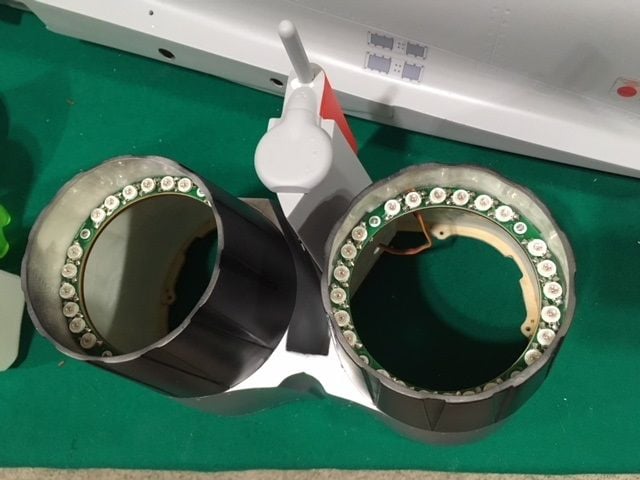
Here's the photos of the installed lighting I said I'd provide. I had already glued the wingtip pods on, so you don't get any internal detail there. Landing lights are shown on an earlier post, but those are not pre-installed anyway.
Wing tip light
Tail light
hatch strobe
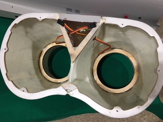
afterburner inside
Wing tip light
Tail light
hatch strobe
afterburner inside
03-26-2018, 05:16 AM
#100
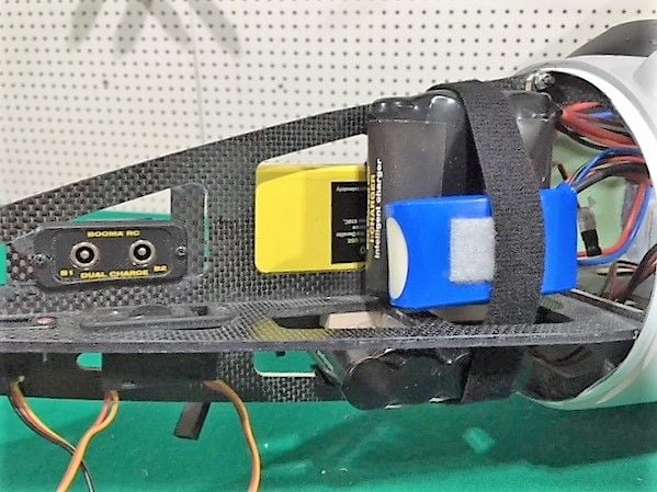
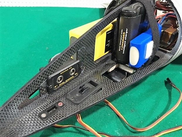
I got a lot done this weekend. As usual, I planned on getting as much weight in the nose as I could to make balancing easier. I have 4 batteries, 2 3000 mah LiFe from Booma RC, the 9.9v Turbine battery, and a small 7.4v LiPo for the lighting. I was able to fit all four into the nose. I had to put one of the main packs underneath. To do that I cut out one of the braces and added a bit of wood to provide a support for the pack. They'll all held in place with Velcro and Velcro straps. I also decided to put the charging jacks up front as well. I used a switch with a jack for the lighting battery so I can shut it off. I noticed the bolts that hold the nose on were not very tight, make sure you check them.