


1/6 F-105 Build Thread
 09-14-2020, 04:26 PM
#701

Thread Starter
My Feedback: (20)
Main gear door fail. Dummy mistake #....what ever!
I had a great weekend at the Flying Tigers Event Of The Year fly in in SC. Three days of great flying, people, and only one rain shower! Got back this weekend and got caught up on yard chores and had about an hour of shop time today. Was going to program the main gear door servos. Easy right! Was supposed to be easy since hinges were in and push rods fabricated. Well when installing the door hinge bolts I discovered that since I added the air intake liners into the wings they interfered with the forward offset hinges. The doors will not close.
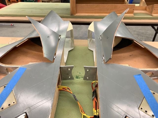
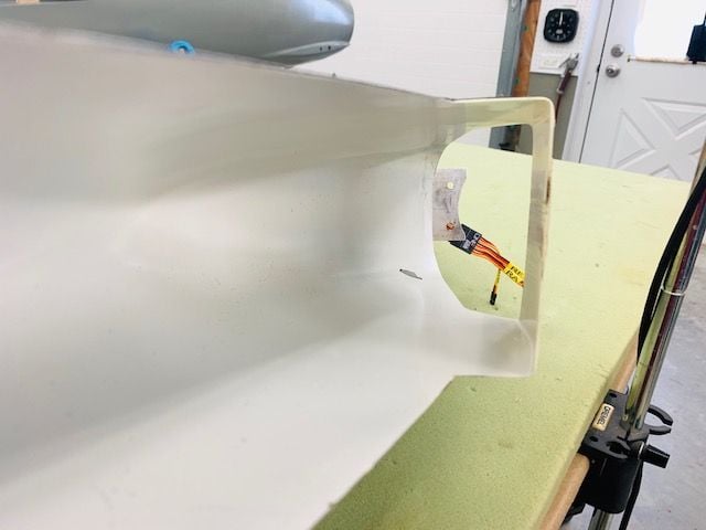
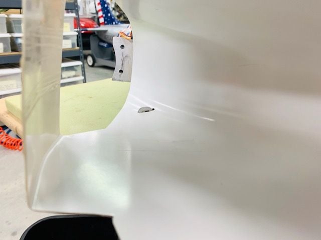
This is as far as the doors will close with the offset hinges hitting the intake liners. I thought there would be clearance when installing the hinges but had never attached the doors since gluing in the intake liners.
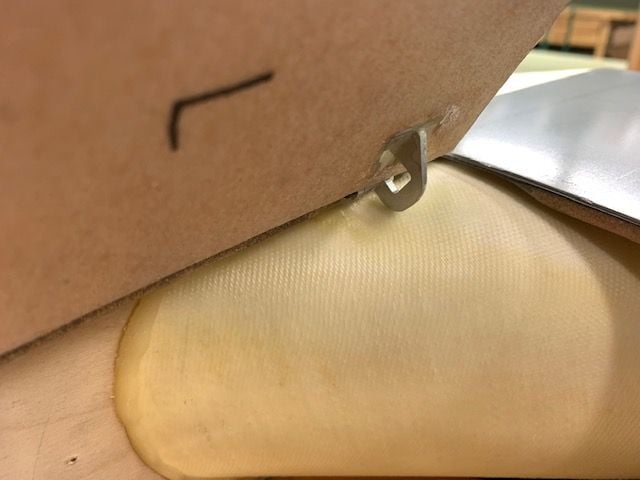
Offset hinge hits the intake liner. One option would be to cut a relief slot into the liner but that would be easily seen looking into the intake and look aweful.
The hinge plates are well epoxied in place and would be difficult to remove without damaging the wing skin and the intake liner so taking them out is not a good option. I am thinking of bridging the gap between the door and the male hinge barrel with a piece of G10 epoxied on the door to the hinge. Then I could cut off the offset arm and the hinge would function like a flat hinge but still use the positioning of the hinge barrel as it is. I will deal with it later...
I had a great weekend at the Flying Tigers Event Of The Year fly in in SC. Three days of great flying, people, and only one rain shower! Got back this weekend and got caught up on yard chores and had about an hour of shop time today. Was going to program the main gear door servos. Easy right! Was supposed to be easy since hinges were in and push rods fabricated. Well when installing the door hinge bolts I discovered that since I added the air intake liners into the wings they interfered with the forward offset hinges. The doors will not close.
This is as far as the doors will close with the offset hinges hitting the intake liners. I thought there would be clearance when installing the hinges but had never attached the doors since gluing in the intake liners.
Offset hinge hits the intake liner. One option would be to cut a relief slot into the liner but that would be easily seen looking into the intake and look aweful.
The hinge plates are well epoxied in place and would be difficult to remove without damaging the wing skin and the intake liner so taking them out is not a good option. I am thinking of bridging the gap between the door and the male hinge barrel with a piece of G10 epoxied on the door to the hinge. Then I could cut off the offset arm and the hinge would function like a flat hinge but still use the positioning of the hinge barrel as it is. I will deal with it later...


The following users liked this post:
yeahbaby (09-14-2020)


 09-15-2020, 06:29 AM
#706

Perhaps take a progressive approach? Cut the slot and close the doors to see how it looks. Maybe even paint the hinge to match the white of the intake. If it bothers you after you get a good look at it, you can then decide to add the bubble / cover over it to clean it up. But I agree with Auburn2, I think with the doors open you will probably never see the hinge through the slot on the ground. But knowing it is there can be a nag. Remember, the first cut is the hardest. 
Last edited by skunkwurk; 09-15-2020 at 06:32 AM.
09-15-2020, 10:07 AM
#707
Thread Starter
My Feedback: (20)
OK, the vote is in. I'll cut the slot and get on with it. After a few days I'll forget about it and be over it. The hinge will be strongest that way anyway. Hopefully I'll get it done later today and have some photos tonight.
I like Thomas's bubble idea a lot. But that's body work and I am making myself not do any non-essential body work till after it passes some test flights in the current grey.
Thanks to all for suggestions.
Gary
I like Thomas's bubble idea a lot. But that's body work and I am making myself not do any non-essential body work till after it passes some test flights in the current grey.
Thanks to all for suggestions.
Gary
Last edited by Viper1GJ; 09-15-2020 at 03:25 PM.
09-15-2020, 03:24 PM
#708
Thread Starter
My Feedback: (20)
Cutting relief slot for MLG door hinge
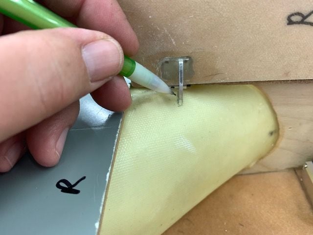
Once I made the decision to cut the slots it was pretty straight forward. Marked each side of the hinge with pencil.
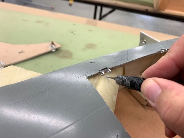
Opened up the slot with a small carbide rotary cutter
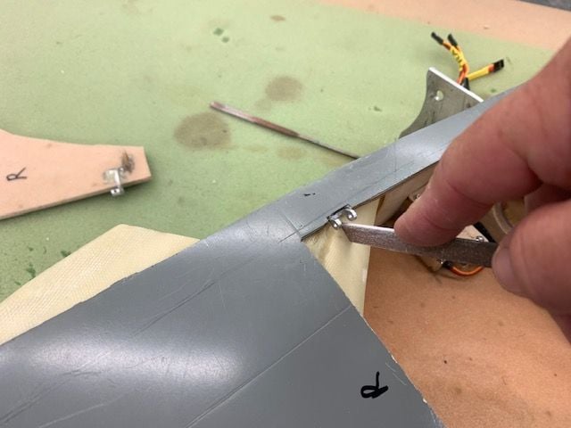
Finished the slot with a perma grit flat file
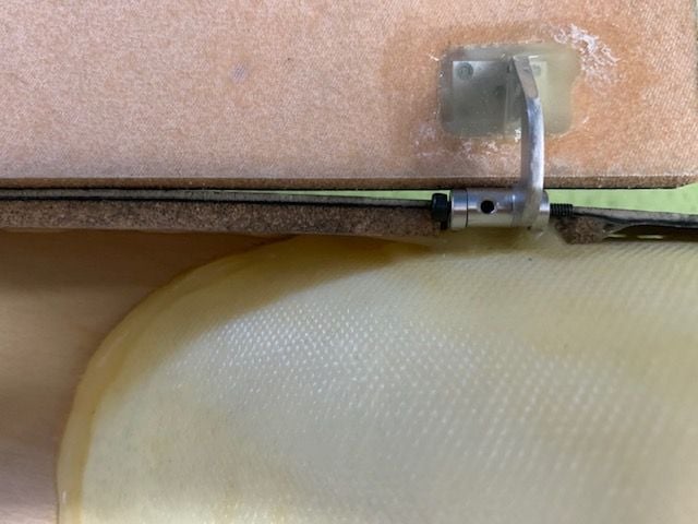
View from inside wing with door about half closed
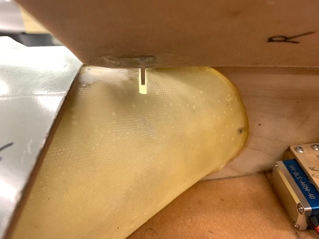
Door closed
Looking down the right side intake with door closed
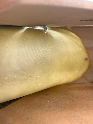
Down the intake on the left side
Once I made the decision to cut the slots it was pretty straight forward. Marked each side of the hinge with pencil.
Opened up the slot with a small carbide rotary cutter
Finished the slot with a perma grit flat file
View from inside wing with door about half closed
Door closed
Looking down the right side intake with door closed
Down the intake on the left side
09-15-2020, 03:29 PM
#709
Thread Starter
My Feedback: (20)
Programming gear door servos
Open and closed end points were programmed for the door servos using the radio and servos plugged into the proper slot in the CB400
Closing...
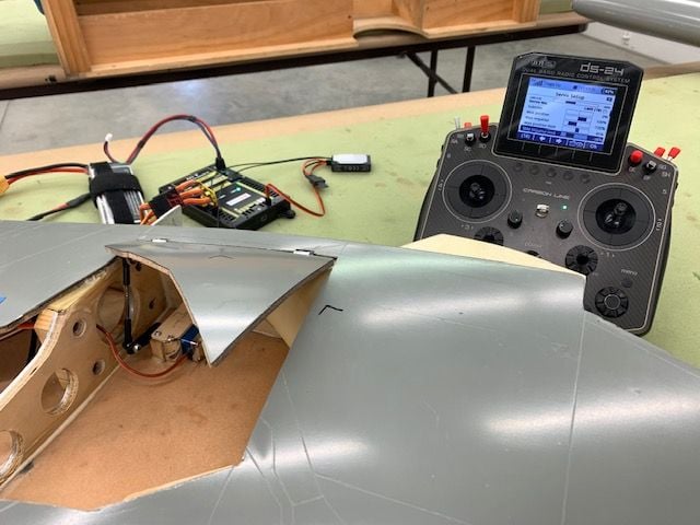
Still closing...
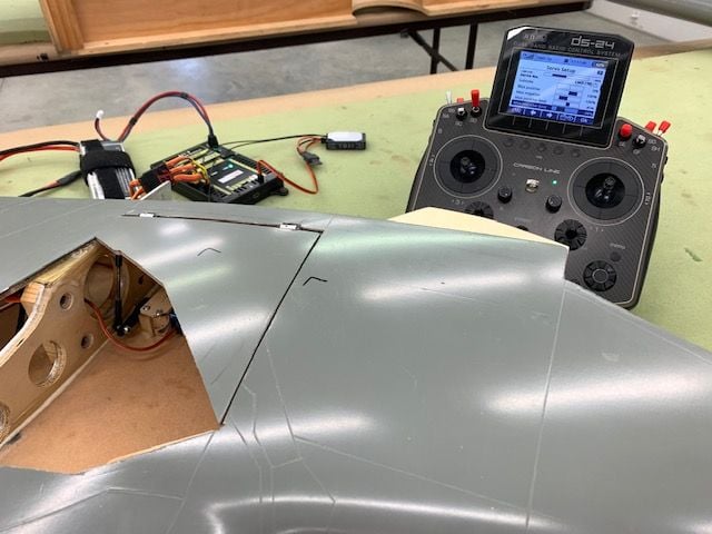
Closed!
Open and closed end points were programmed for the door servos using the radio and servos plugged into the proper slot in the CB400
Closing...
Still closing...
Closed!
09-15-2020, 03:36 PM
#710
Thread Starter
My Feedback: (20)
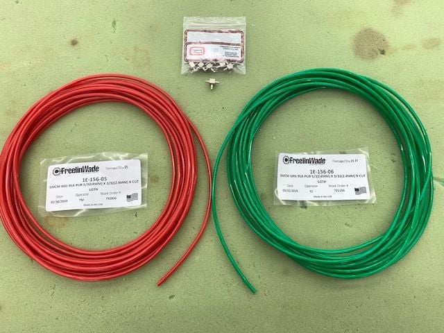
4mm Tees arrived
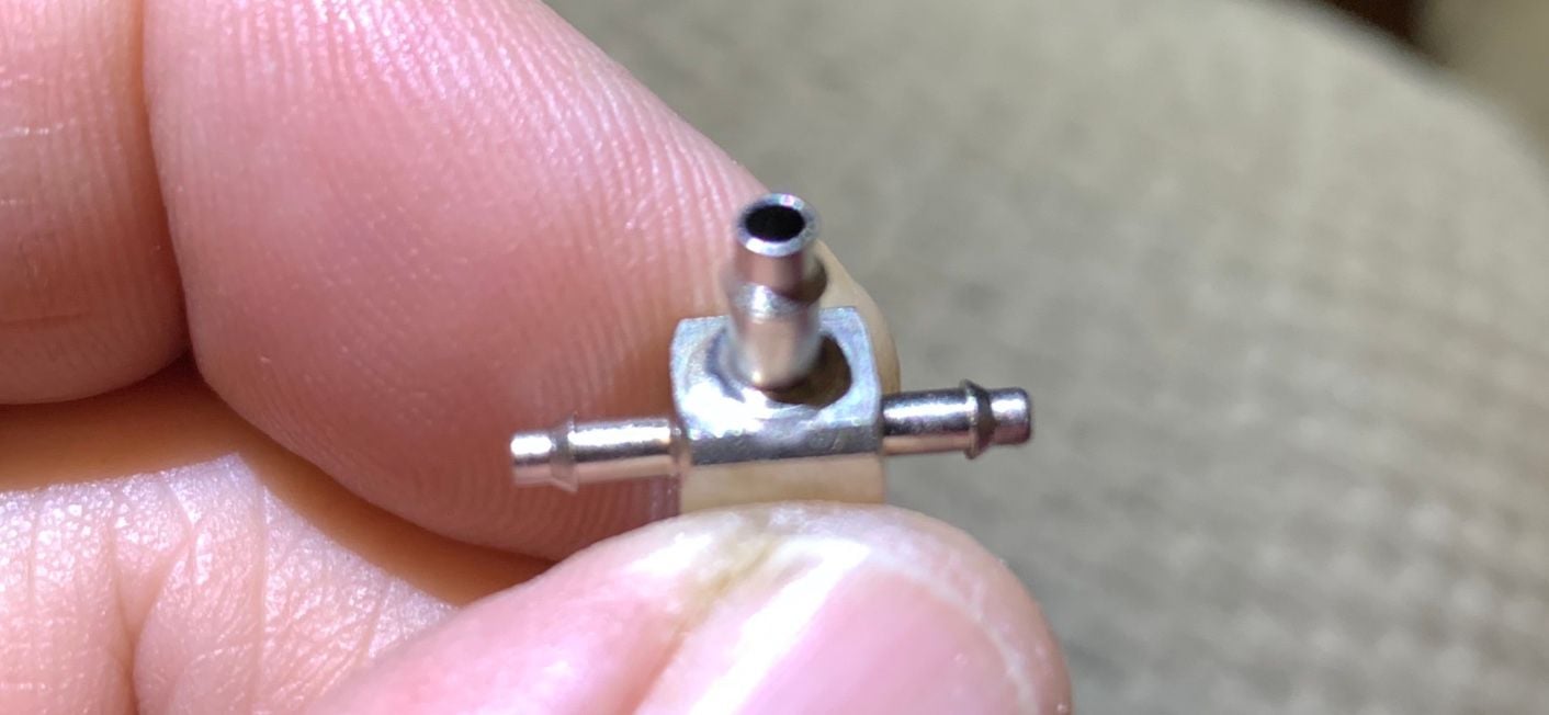
Found these 4mm to 3mm Tees from Clippard. They arrived today.
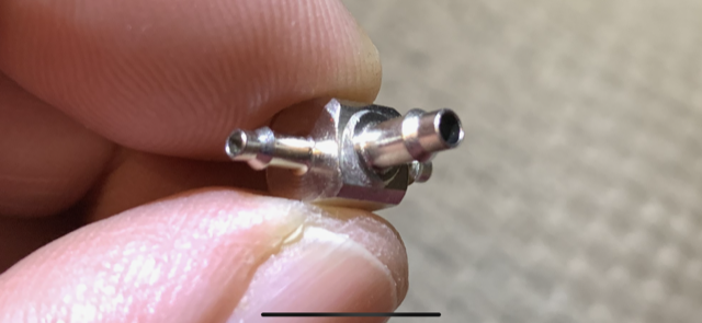
I'll try these on the gears to allow 4mm higher flow air line to feed both cylinders. These will be smaller in size than the push to connect T.
Found these 4mm to 3mm Tees from Clippard. They arrived today.
I'll try these on the gears to allow 4mm higher flow air line to feed both cylinders. These will be smaller in size than the push to connect T.
09-16-2020, 03:40 PM
#711
Thread Starter
My Feedback: (20)
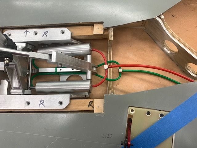
Hooking up nose gear air lines
The 4mm to 3mm Tees came in yesterday along with the 4mm air line. I got the Tees from Clippard and the airline from McMaster Carr.
Nose gear air lines installed after some trial and error to get an acceptable fit. Hopefully the 4mm feed lines will supply plenty of air to the cylinders through the Tee on each side.
Air line dry fit to see if it would work with retract and extend cycle. So far so good.
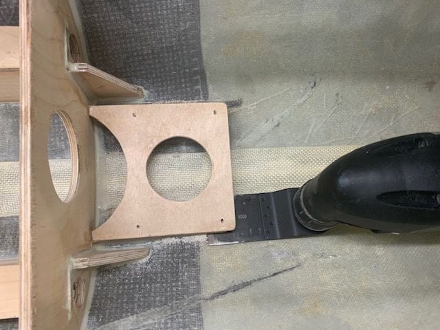
Equipment tray installed to check for interference. It actually worked well under the tray. The hole in the tray for the cylinders will have a bump up cover when finished.
The 4mm to 3mm Tees came in yesterday along with the 4mm air line. I got the Tees from Clippard and the airline from McMaster Carr.
Nose gear air lines installed after some trial and error to get an acceptable fit. Hopefully the 4mm feed lines will supply plenty of air to the cylinders through the Tee on each side.
Air line dry fit to see if it would work with retract and extend cycle. So far so good.
Equipment tray installed to check for interference. It actually worked well under the tray. The hole in the tray for the cylinders will have a bump up cover when finished.
09-16-2020, 03:52 PM
#712
Thread Starter
My Feedback: (20)
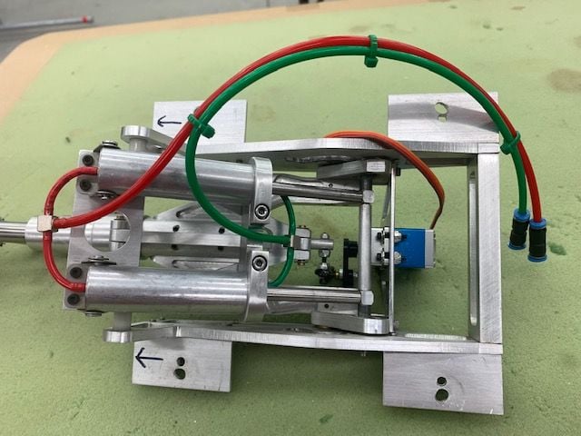
Main gear air lines hooked up
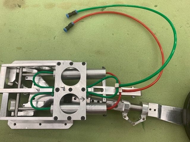
It was not what I expected hooking up the main gear air lines. There was no space for the green lines to connect inside the gear frame and not get smashed by the movement of the gear cylinders. I had to figure out a way to route the lines out the wing root side to connect the Tee. The red was no problem. I'm glad I found he smaller Tees instead of the push to connect type due to their larger size. Thanks for he suggestions to look at Clippard.
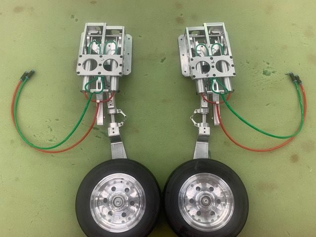
Main gear lines done.
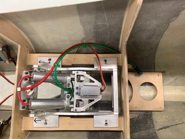
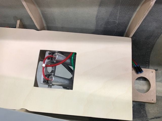
Lines run out the wing root side and then out of the wing. There is enough room for the flex needed as the cylinders move back and forth.
Lines run out the wing. I still have to figure out where to stuff the extra length when hooking up the wing. TBD.
It was not what I expected hooking up the main gear air lines. There was no space for the green lines to connect inside the gear frame and not get smashed by the movement of the gear cylinders. I had to figure out a way to route the lines out the wing root side to connect the Tee. The red was no problem. I'm glad I found he smaller Tees instead of the push to connect type due to their larger size. Thanks for he suggestions to look at Clippard.
Main gear lines done.
Lines run out the wing root side and then out of the wing. There is enough room for the flex needed as the cylinders move back and forth.
Lines run out the wing. I still have to figure out where to stuff the extra length when hooking up the wing. TBD.
09-16-2020, 04:11 PM
#714
Thread Starter
My Feedback: (20)
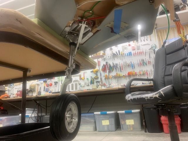
First air test of main gear retraction
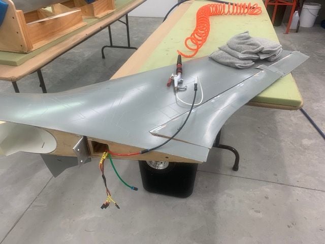
I hooked up the right main gear to the shop air compressor for a "just see if it would work" test. Weights were placed on the wing to hold it on the table. The shop compressor was reading about 105 psi.
The first extension test just about tore the gear mounts out of the wing. It was violent! With the massive weight of the main gear and wheel it went out fast with a bang! The retraction was the same. I was glad my hand was clear.
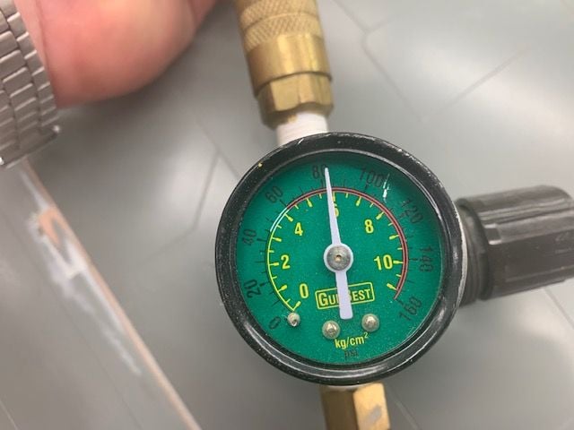
I added a regulator for the next test. With the pressure set at 80 psi it was still way too fast.
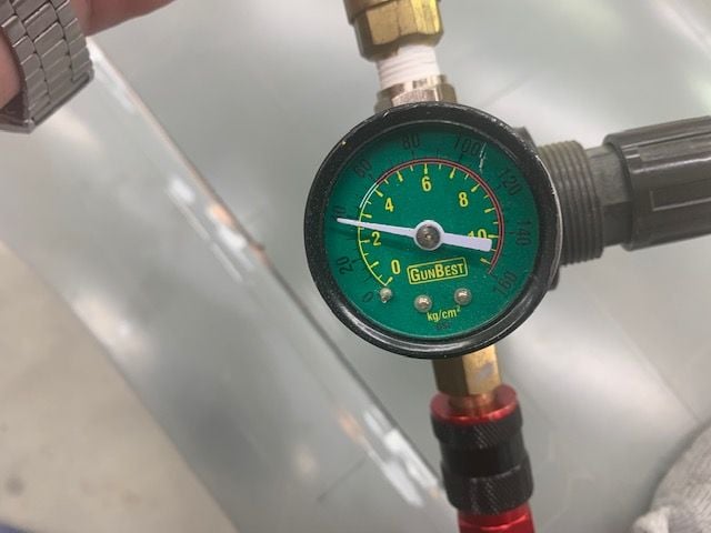
I dropped the pressure to 40 psi and it seemed much better. I ran out of time here but it seems that I will need to control the flow rate to slow the speed and the force which the gear has when moving. I will have to think about how to do this. The air flow pushing against the main gear when retracting will also slow it. At least on this first test the main gear seems to have enough power to easily retract. This was one of my major concerns at the beginning of the project. Suggestions welcome.
Thanks,
Gary
I hooked up the right main gear to the shop air compressor for a "just see if it would work" test. Weights were placed on the wing to hold it on the table. The shop compressor was reading about 105 psi.
The first extension test just about tore the gear mounts out of the wing. It was violent! With the massive weight of the main gear and wheel it went out fast with a bang! The retraction was the same. I was glad my hand was clear.
I added a regulator for the next test. With the pressure set at 80 psi it was still way too fast.
I dropped the pressure to 40 psi and it seemed much better. I ran out of time here but it seems that I will need to control the flow rate to slow the speed and the force which the gear has when moving. I will have to think about how to do this. The air flow pushing against the main gear when retracting will also slow it. At least on this first test the main gear seems to have enough power to easily retract. This was one of my major concerns at the beginning of the project. Suggestions welcome.
Thanks,
Gary
09-16-2020, 05:00 PM
#716
I would also test with the production flight hardware (valves & tanks). I see you adjusted pressure down, that is a good test. But the volume of air you�re able to push from the air compressor is exponentially higher than from the tanks we carry in Jets. Is it the shop compressor you�re using to test?
09-16-2020, 05:11 PM
#717
Thread Starter
My Feedback: (20)
The air flow will tend to pull the gear out once started so it will slam hard against the stops on the way out. I need to see if I can control the flow rate so there is enough speed to drop it and then push the cam over center to lock it down with out yanking out the gear mounts.
I'll start looking for the 4mm adjustable flow valves. I think it was you that suggested Clippard. Great idea. Thanks.
09-16-2020, 05:20 PM
#718
Thread Starter
My Feedback: (20)
Yes you are correct. It was the shop compressor. I have 2 1000ml bottles for the gear system so actual tests will have to be with the tanks and valves that will be in the jet. I'm using 4mm tubing and fittings from fill valves, to tanks, to EVO hi flow 4mm valves, to gears, to the 4mm to 3mm Tees in the photos. We will see soon what we actually have for volume and flow.
Thank,
Gary
Thank,
Gary
Last edited by Viper1GJ; 09-16-2020 at 05:36 PM.

The following users liked this post:
Viper1GJ (09-16-2020)
09-17-2020, 08:41 AM
#720

Thomas, actually it works the opposite. Due to the swept wing the main gear actually retracts forward into the wind. What makes it worse is the strut and door rotation when it starts retracting. During the first half of the gear swing the gear door is actually catching wind from the air flow like a big speed brake. As it folds into the wing it starts to get more streamlined. This was why I was concerned about the ability to lift the massive gear and wheel weight and also fight the air flow. I'll do some more tests tomorrow by pushing against the gear when retracting to see how much excess power there is in the retraction cycle.
The air flow will tend to pull the gear out once started so it will slam hard against the stops on the way out. I need to see if I can control the flow rate so there is enough speed to drop it and then push the cam over center to lock it down with out yanking out the gear mounts.
I'll start looking for the 4mm adjustable flow valves. I think it was you that suggested Clippard. Great idea. Thanks.
I know all the scale purists will balk at the idea but we are not using hydraulics like the real one. FYI, hellcats, corsairs and Dauntless dive bombers all used G to help swing the gear out when they returned to the ship. It minimized the number of hand revolutions needed to get the gear down and locked.
keep up the great work
Last edited by yeahbaby; 09-17-2020 at 11:28 AM.
09-17-2020, 05:18 PM
#722
Thread Starter
My Feedback: (20)
Tom, it was one of those days here, spent all day trying to figure out where to put stuff, wiring, plumbing, found out nose wheel hits equipment tray, main gear wont retract all the way in wing, and everything is in everything else's way. Started re-engineering what I engineered yesterday. Day gone and got nothing done...Arrrgh!
09-18-2020, 02:28 PM
#723
Thread Starter
My Feedback: (20)
Spent the last two days pondering how to proceed.
I installed a flow control valve and I got the main gear swing working ok. However, this is the first time I have tested it with the wing right side up and as someone discussed before it does not fully retract into the wheel well due to gravity hang even when the it is locked up. There is enough slop in the gear retract itself plus the improper rotation angle cause by correcting the tow angle when extended to cause the front of the tire to hang about 1/2" below the wheel well and wing skin. Too much to deal with now so I'm going to ignore it for a while and work on stuff I can fix.
Next I found out that the nose wheel contacts the bottom of the equipment tray and keeps it from laying flat across the formers. It needs to be about 1/4" higher. If it is higher the servo wires plugged into the CB400 contact the bottom of the cockpit tub. My plan to mount the the receivers and air valves on the tray with wires and plumbing under the tray ran into problems also. The wires and air lines would likely contact the nose retract mechanics and or door servos and get cut or pinched. The air valves mounted to the tray would also bump into the bottom of the cockpit tub and would be difficult to lift up the tray with all the connections.
So I spent the last two days plotting on how to start over. I will cut a small relief hole in the tray for the nose wheel. I will move the CB400 forward out of cockpit area to allow vertical space for the servo wires and mount it up on the tray about 1/4" higher to clear the nose wheel. In this area there is room on each side to feed the servo wires up to the top of the tray with out getting in the nose gear retract or servo doors. It will also help move weight forward. The 4 receivers will be mounted to the fuse sides to avoid wires under the tray near the servo doors or retract system.
I will move the air valves to the rear off the tray and mount to the floor of the fuse where the air trap tank was going to go. The air fill valves and guages will be here also. All the air system is fixed to the fuse and will not have to be disconnected to service the electronics tray.
I will make a fuel system tray that will mount on top if the retract air tanks just in front of the fuel tank. This tray will hold the air trap tank, fuel pump, and fuel filter. I should be able to remove the entire fuel system including the fuel tank once the air tanks are removed without disconnecting anything except the fuel line to the turbine at the fuel valve. The fuel system tray and tuel tank will clear the air valves when removing them if the air valves are mounted forward and low enough.
Now that we have a new plan I got started on some demo. I cut and ground out the old air trap tank mount. Ran out of time so more to come.
09-18-2020, 02:36 PM
#724
Sounds like she is putting up a fight. Im sure you�ll get her! A friend of mine has a large Mig-29 that puts up a pretty tough fight every time we work on her. On the Mig I had to program a nose wheel offset when in a fully retracted state to solve for a similar issue. I�m sure you thought about that, if not, it may be a less intrusive fix.
09-18-2020, 02:38 PM
#725
Thread Starter
My Feedback: (20)
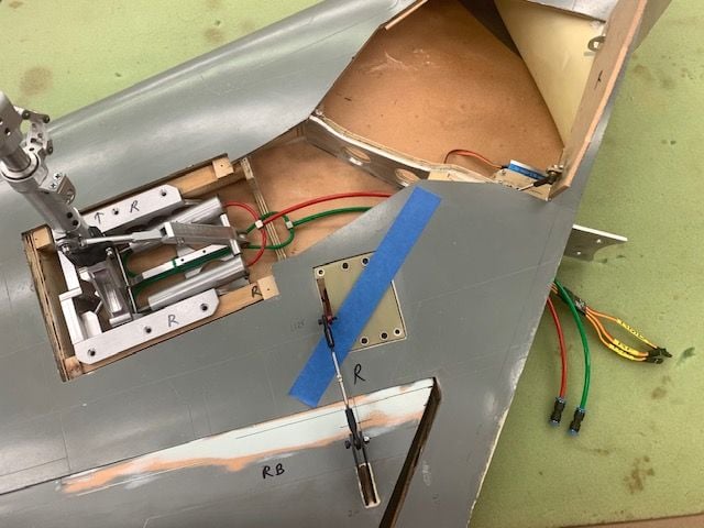
New air valve layout and air trap tank mount demo
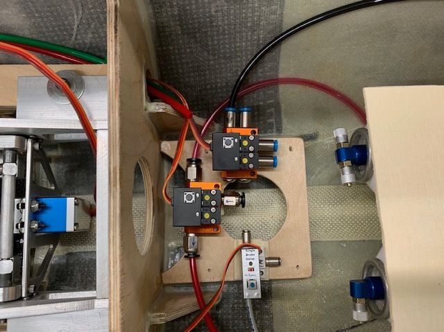
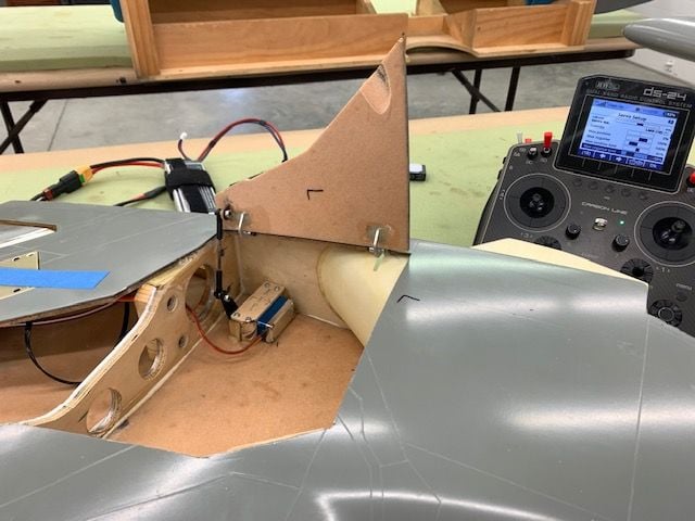
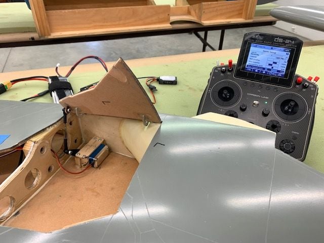
This was the dry fit layout test for the air valves. Top is the retract valve, center is the brake valve, and bottom is the drag chute valve. To the right is the fuel system tray mock up on top of the air tanks. I may extend it forward over the air valves if the air trap tank will clear the cockpit tub.
Old tank mount cut out
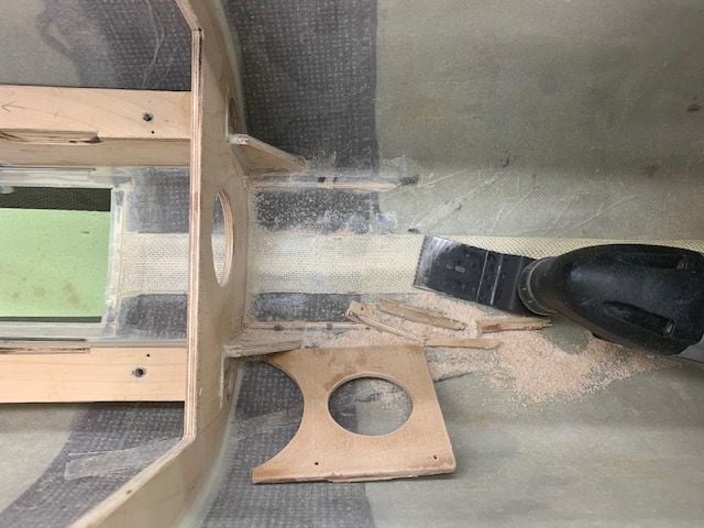
Its like the home remodel shows on TV...Demo Day!
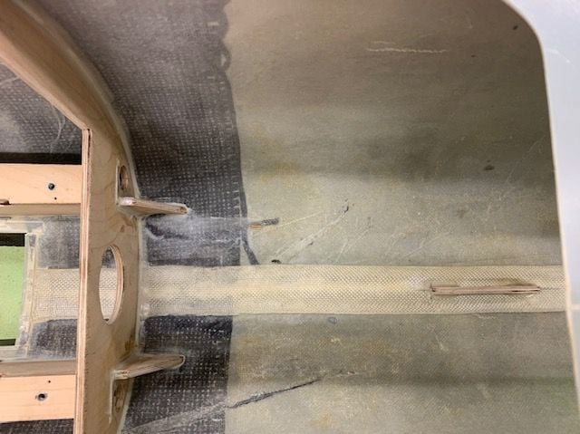
Cleaned up and ready to start over. Need some sleep, ready to try again.
This was the dry fit layout test for the air valves. Top is the retract valve, center is the brake valve, and bottom is the drag chute valve. To the right is the fuel system tray mock up on top of the air tanks. I may extend it forward over the air valves if the air trap tank will clear the cockpit tub.
Old tank mount cut out
Its like the home remodel shows on TV...Demo Day!
Cleaned up and ready to start over. Need some sleep, ready to try again.