


1/7 Scale Blackburn Buccaneer All Composite Scratch Build


 06-15-2019, 02:32 PM
#277
After a small pause on the Buccaneer while I started on another of my bucket list projects (all composite Spitfire starting from full scale measurements (the Monforton book) to a CAD model) I'm back on the Buccaneer.
I have been working some aspects at a low level, with the main accomplishment of getting some significant parts of the main gear retracts built.With the design set and proven by a 3D printed version, after failing to find a custom builder/ machine shop willing to take on the project, I started sending parts out to the on-line machine shop vendors.
A friend has a mini-lathe, so we started by making the main pivot shafts and the pull-up bars. Next up were getting the shrink linkage machined, followed by the main retract frame, which have all been assembled. It is looking good so far, but I'm still considering options for the main leg. None of this is cheap, especially for only a couple of copies of each part. Bulk ordering drives the unit costs down, but I don't need 50 or 100 retracts, at least without proving the first one works.
I hope!!
06-15-2019, 05:24 PM
#278

Nige,
I've posted over on the other site, rcscalebuilder.com
https://www.rcscalebuilder.com/forum...607&PN=1&TPN=1
They are sized for the Brian Taylor 1:5.33 scale (83" span) Spitfire IX. I plan on using the VicRC glass fuselage.
The first parts out were a little rough, but with lessons learned, the next set should be better.
A couple of teaser shots.......
Paul
 06-16-2019, 11:23 AM
#279
Nige,
I've posted over on the other site, rcscalebuilder.com
https://www.rcscalebuilder.com/forum...607&PN=1&TPN=1
They are sized for the Brian Taylor 1:5.33 scale (83" span) Spitfire IX. I plan on using the VicRC glass fuselage.
The first parts out were a little rough, but with lessons learned, the next set should be better.
A couple of teaser shots.......
Paul
I've posted over on the other site, rcscalebuilder.com
https://www.rcscalebuilder.com/forum...607&PN=1&TPN=1
They are sized for the Brian Taylor 1:5.33 scale (83" span) Spitfire IX. I plan on using the VicRC glass fuselage.
The first parts out were a little rough, but with lessons learned, the next set should be better.
A couple of teaser shots.......
Paul
I've bookmarked the other page!
I'm surprised you have time to sleep, never mind work and eat...!
06-20-2019, 06:44 PM
#280
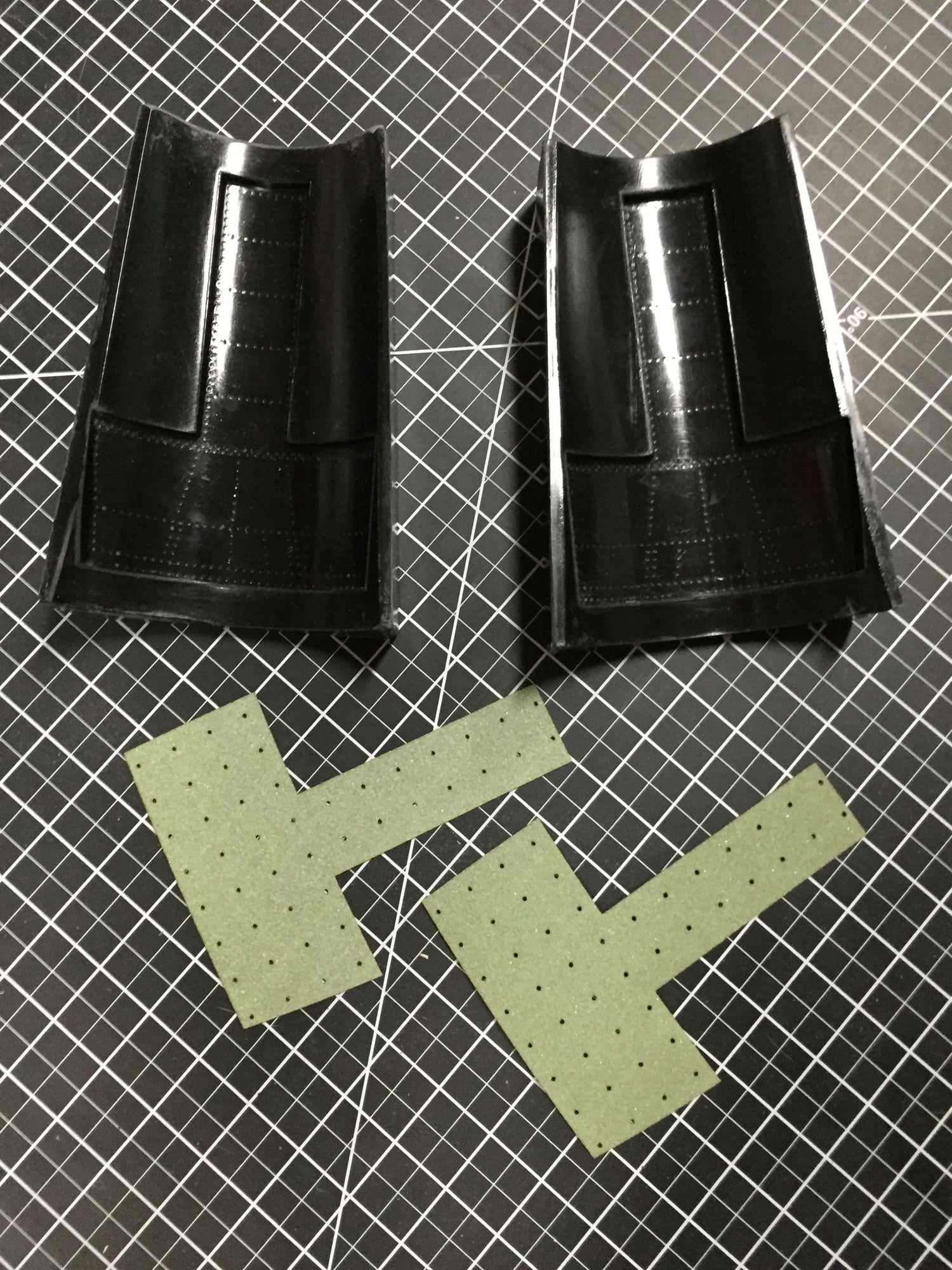
After getting a delivery of 9oz glass cloth, I was able to finish the speedbrake drag link molds.
I will make the actual drag link parts this weekend
While I was at it, I cut out the Airex skins for the drag links.
Paul
I will make the actual drag link parts this weekend
While I was at it, I cut out the Airex skins for the drag links.
Paul
Last edited by JSF-TC; 06-20-2019 at 07:07 PM.
06-22-2019, 09:20 PM
#282

Join Date: Sep 2013
Posts: 631
Likes: 0
Received 0 Likes
on
0 Posts
You work is very beautyful!!! I like very much you work!
06-23-2019, 01:09 AM
#283

 07-07-2019, 08:22 AM
#285
I assembled one of the retract units with the machined parts I have received so far and used the 3D printed test parts for the rest, just to test the entire system.
https://www.youtube.com/watch?v=7DJM...ature=youtu.be
Paul
https://www.youtube.com/watch?v=7DJM...ature=youtu.be
Paul
Last edited by JSF-TC; 07-07-2019 at 08:28 AM.
07-07-2019, 08:27 AM
#286
[youtube]https://www.youtube.com/watch?v=7DJMqvLXxbY&feature=youtu.be[/youtube]
Struggling on how to post YouTube videos. Help appreciated from the experts. The thread that comes up when I Google it doesn't seem to help.
Struggling on how to post YouTube videos. Help appreciated from the experts. The thread that comes up when I Google it doesn't seem to help.
Last edited by JSF-TC; 07-07-2019 at 08:30 AM.
07-07-2019, 08:34 AM
#287
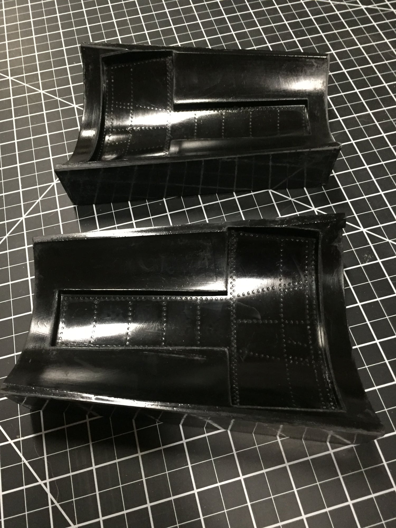
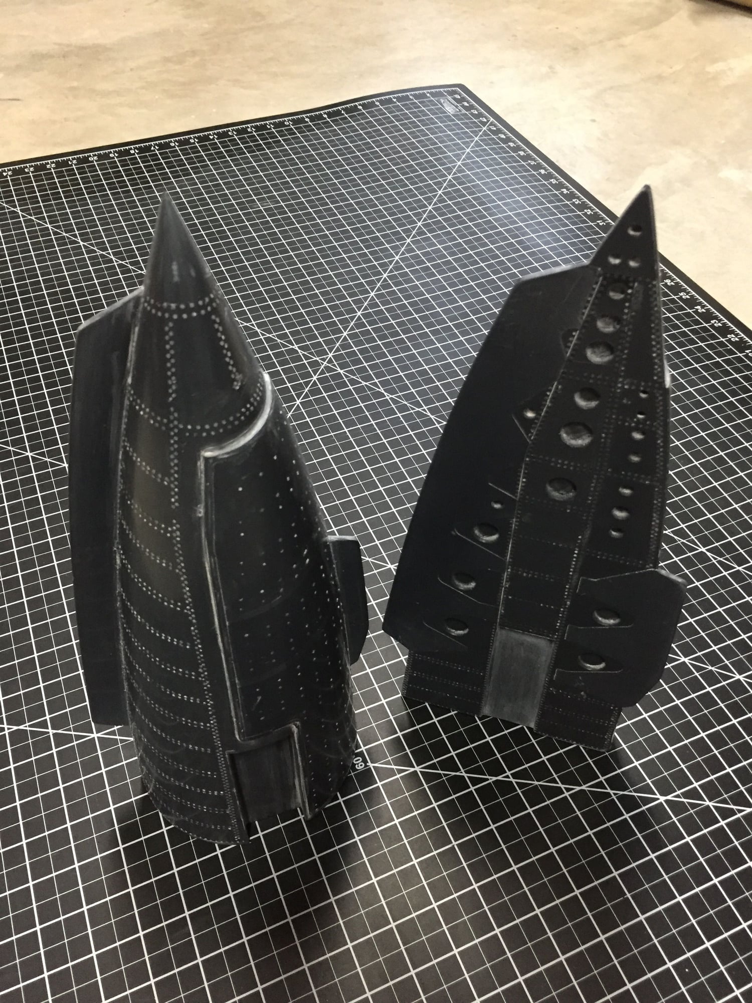
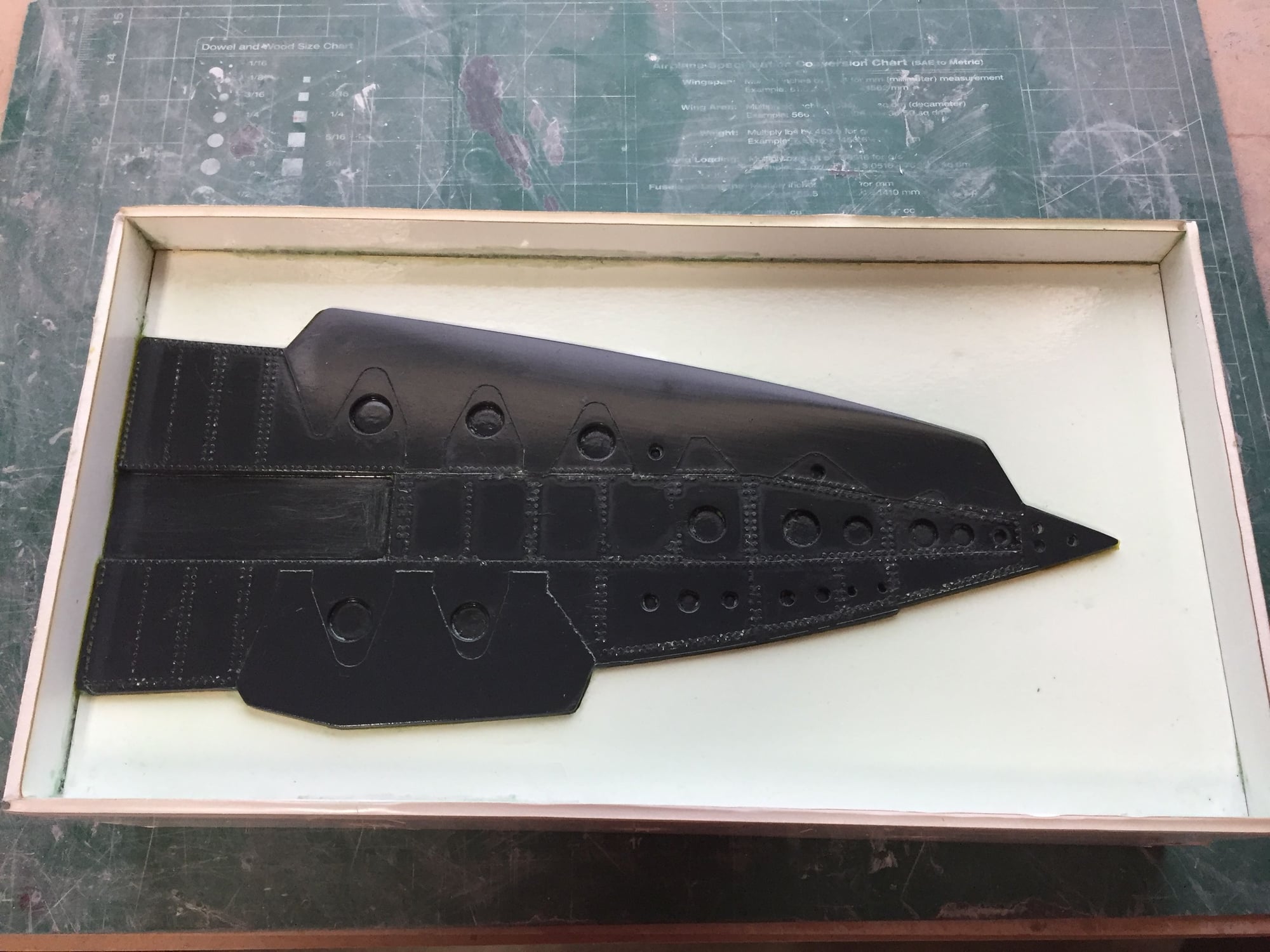
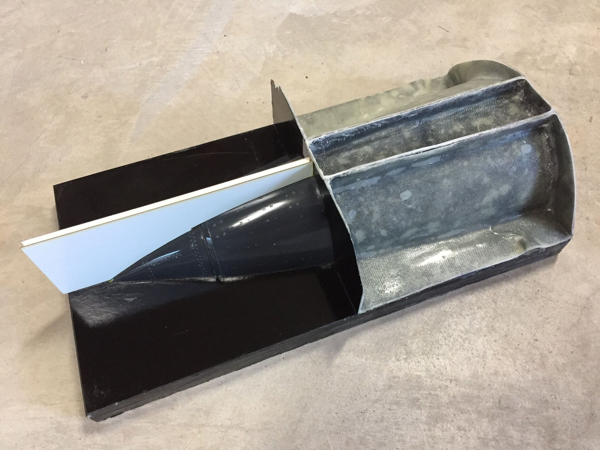
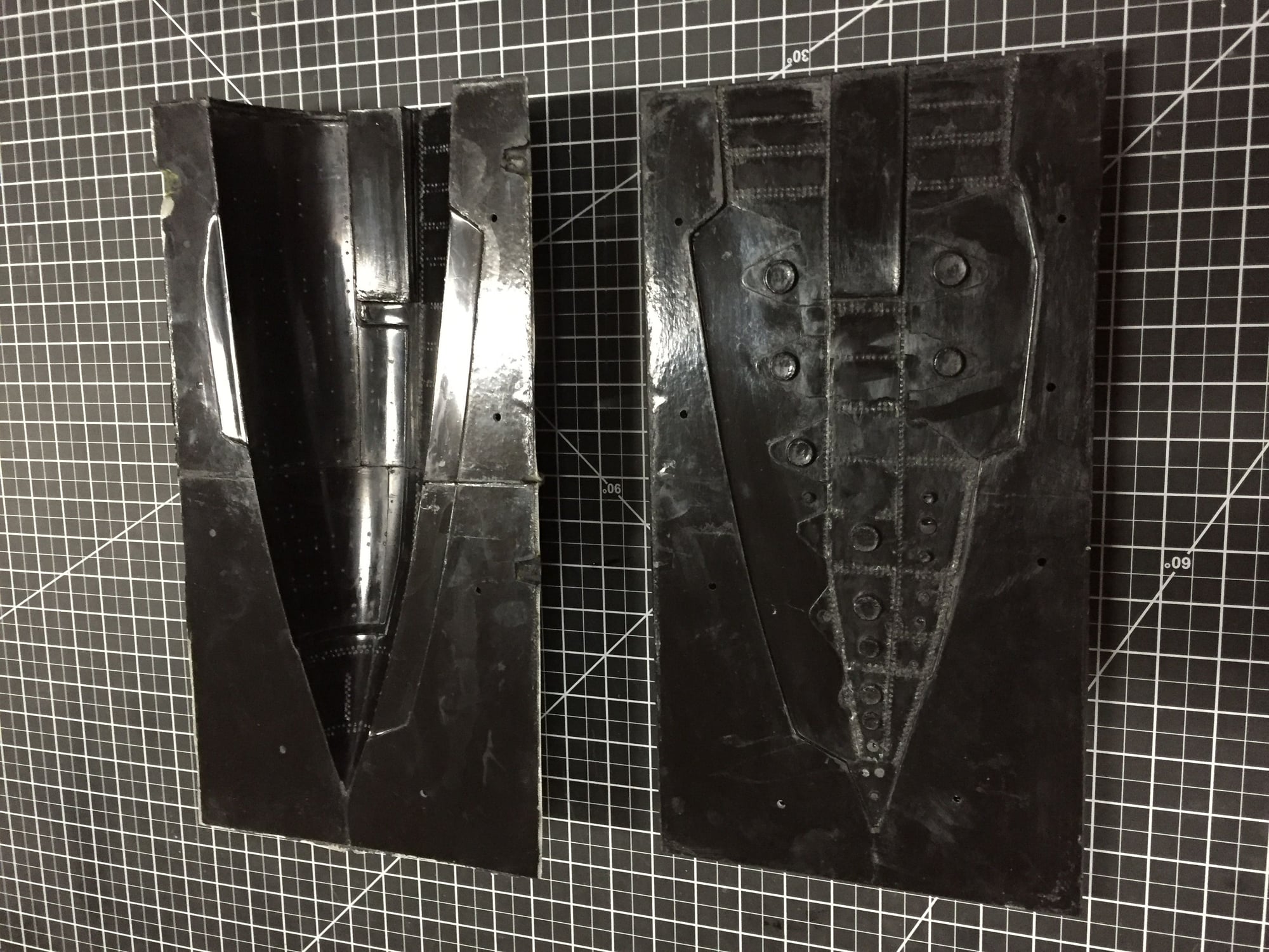
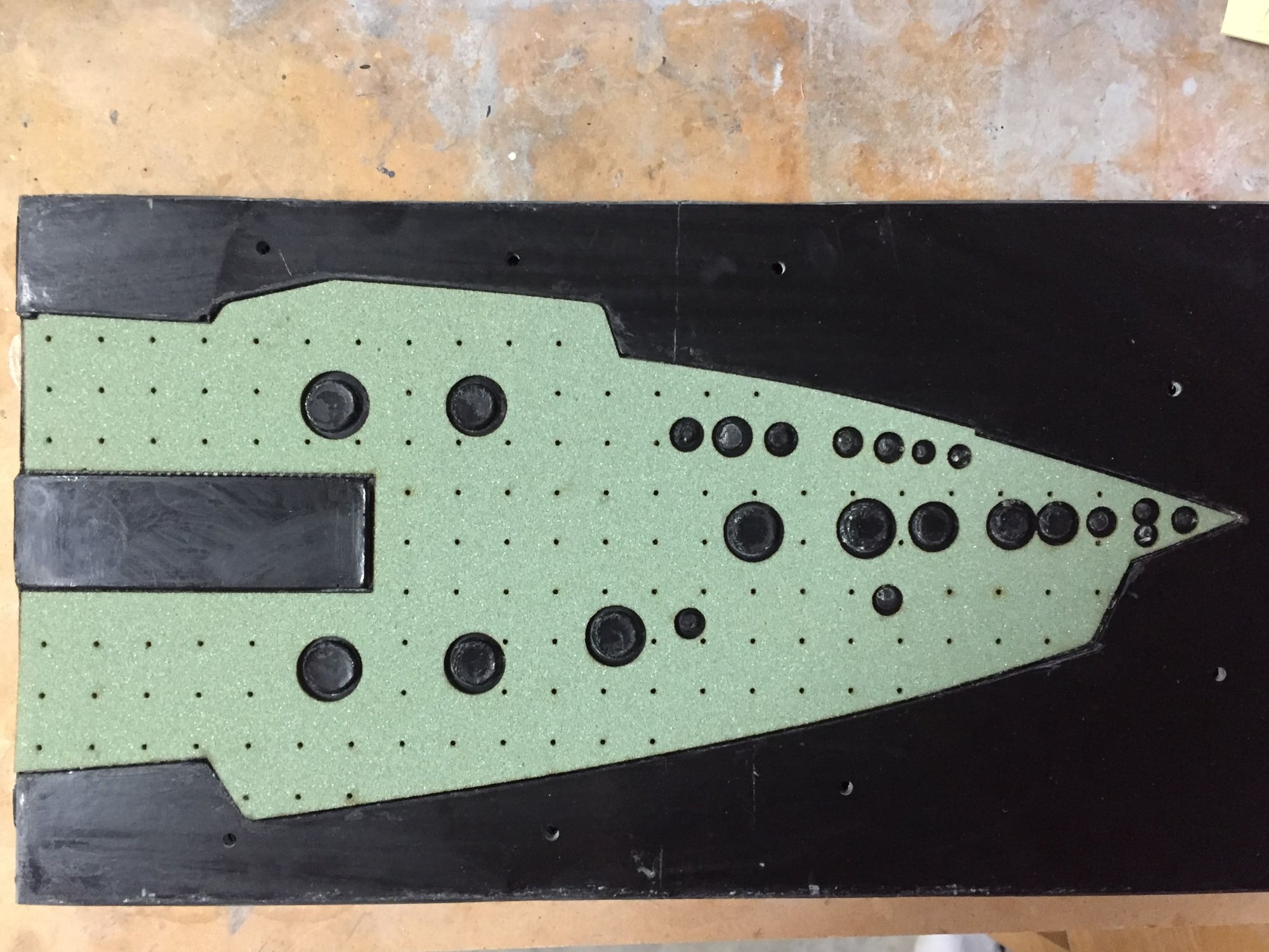
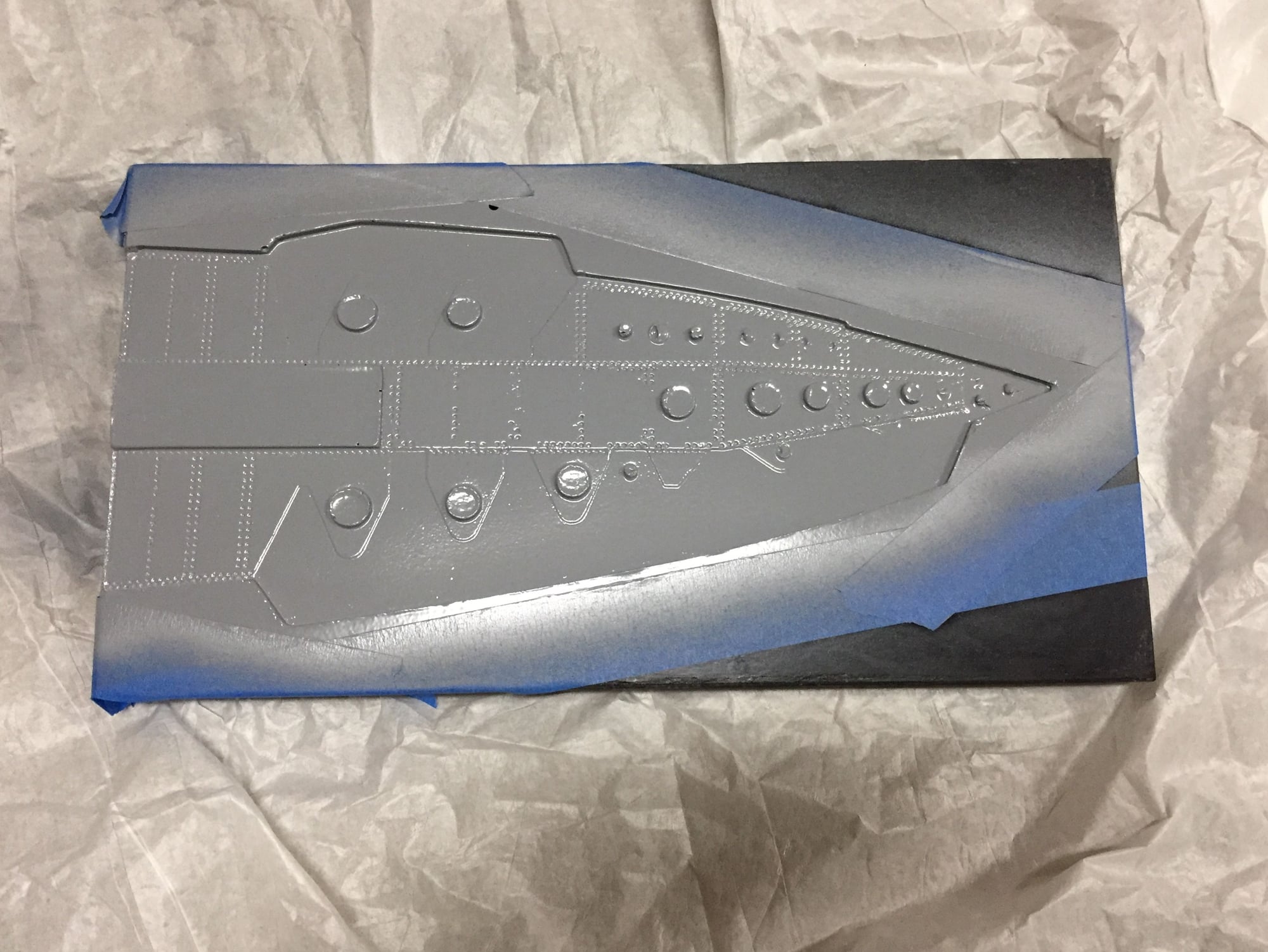
I finished the second build of the speedbrake plugs and started on making the molds for one of them. I have the parting plane made and the surface coat applied. Should be able to get the glass down later today.
I am using wax & PVA this time as it seems to handle the raised surface detail much better than the Frekote. I am only going to work on one at a time so if this attempt fails like last time I will only have to make one speedbrake petal, not both. The outer surface molds will be multi-part to help them release from the plug.
I am using wax & PVA this time as it seems to handle the raised surface detail much better than the Frekote. I am only going to work on one at a time so if this attempt fails like last time I will only have to make one speedbrake petal, not both. The outer surface molds will be multi-part to help them release from the plug.
07-07-2019, 01:45 PM
#288
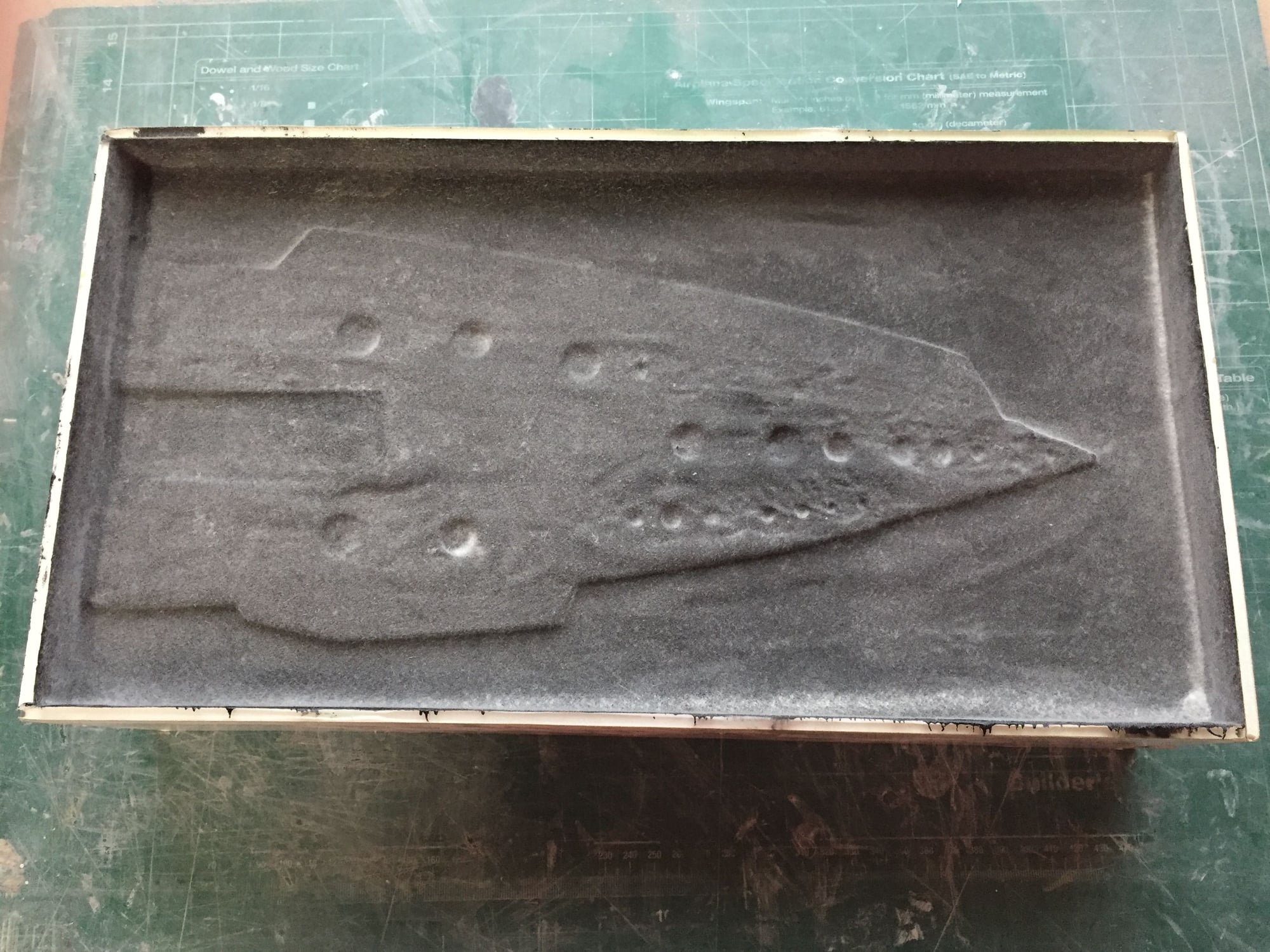
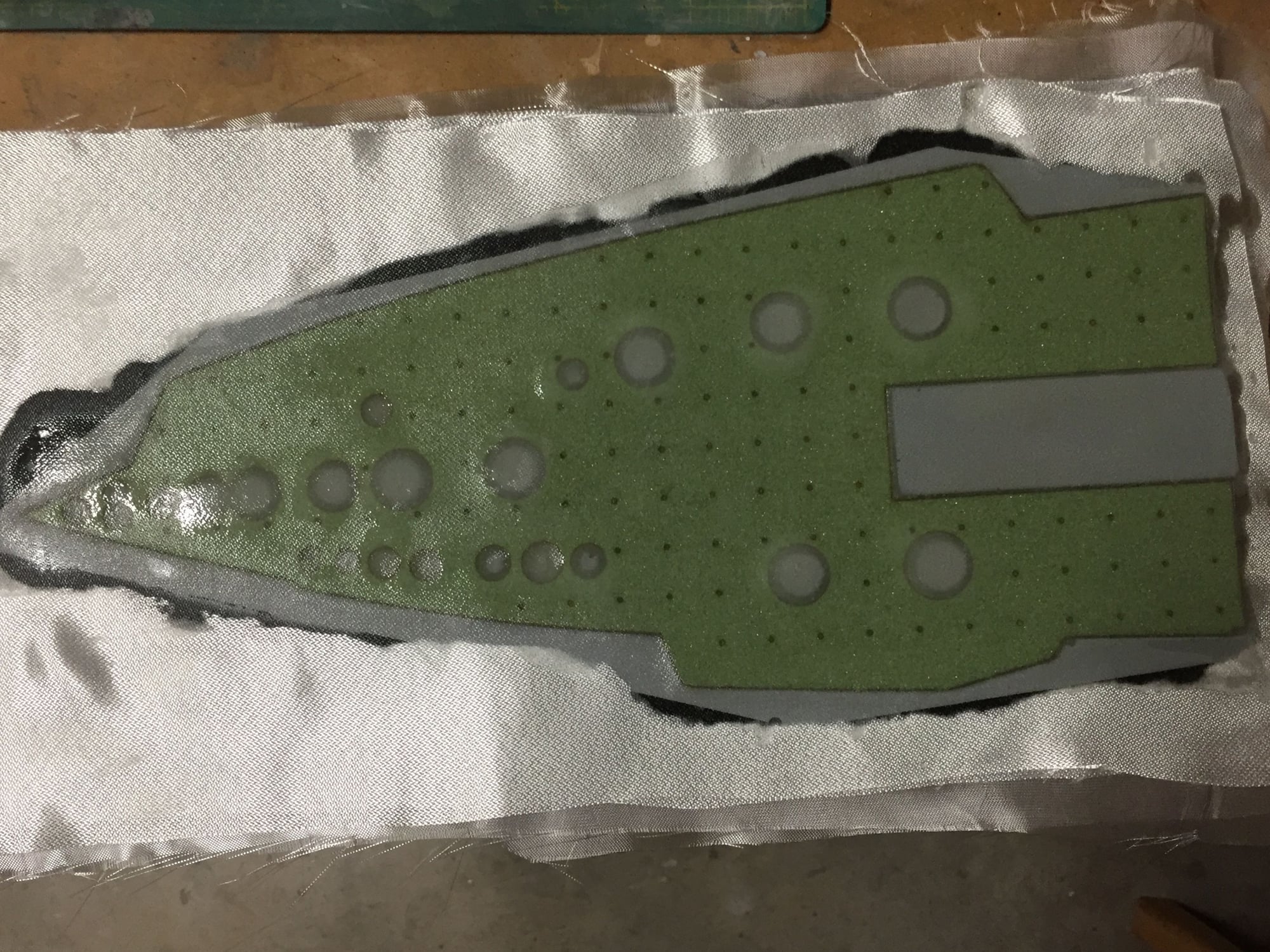
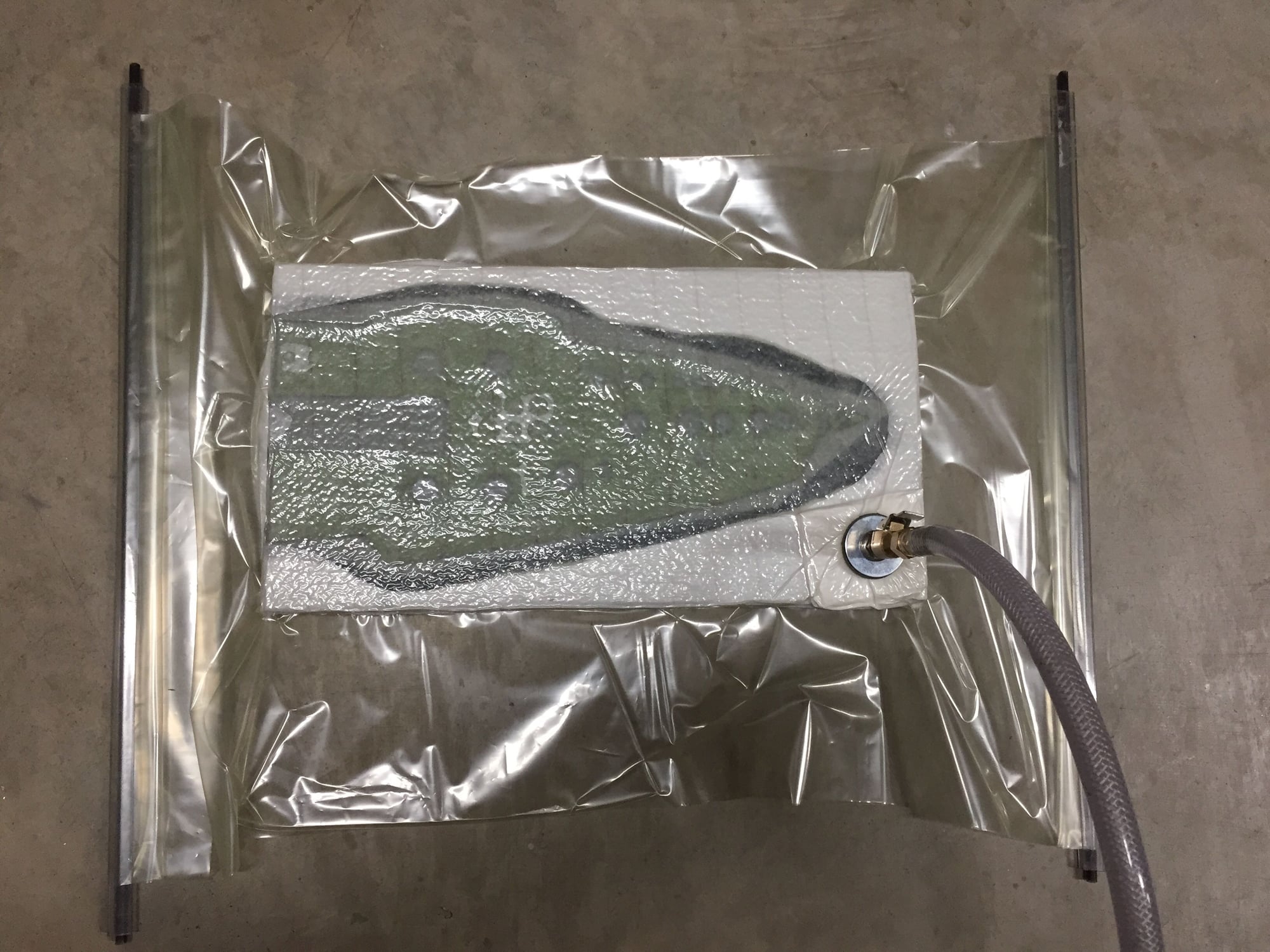
First half of the mold completed. Looks good so far. 6 layers of 9oz glass for the mold.
It can sit all week before I work on the second side as I'm away on a work trip.
I laid the surface coat down at 08:30 this morning, and by 16:30 the glass/ epoxy had cured. 90F+ in the garage certainly has some advantages.
Paul
It can sit all week before I work on the second side as I'm away on a work trip.
I laid the surface coat down at 08:30 this morning, and by 16:30 the glass/ epoxy had cured. 90F+ in the garage certainly has some advantages.
Paul
08-16-2019, 05:47 PM
#289
After what seems like ages, here's an update. Slow progress due to work, vacation and it being over 100F in the garage which slows progress significantly.
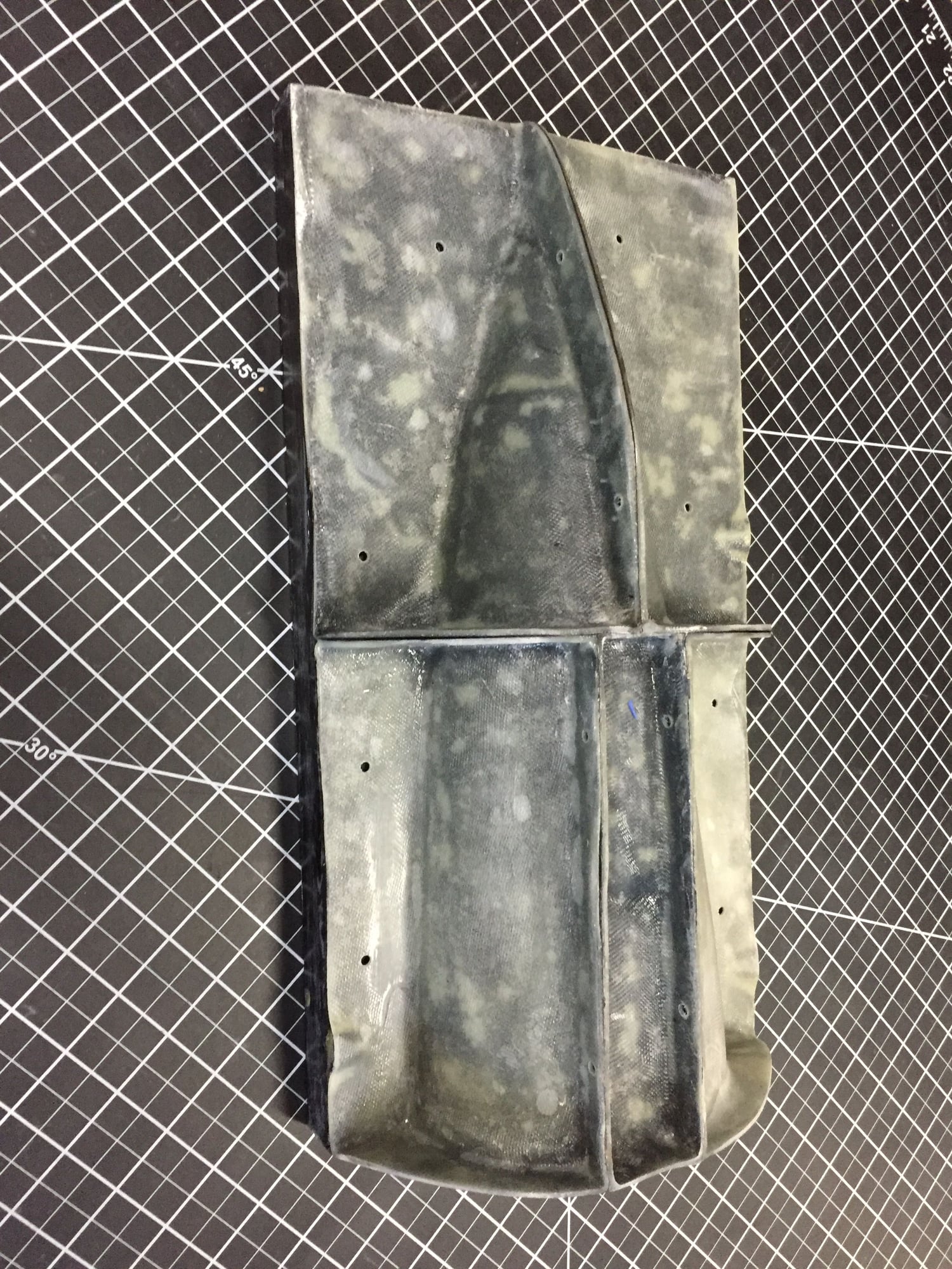
I continued with the speedbrake mold, finally ending up with a usable set for the first half. The plug did split as I was trying to free it from the base mold part, but no damage to the mold.
I just have to do it all again for the other side.
I continued with the speedbrake mold, finally ending up with a usable set for the first half. The plug did split as I was trying to free it from the base mold part, but no damage to the mold.
I just have to do it all again for the other side.
08-16-2019, 05:51 PM
#290
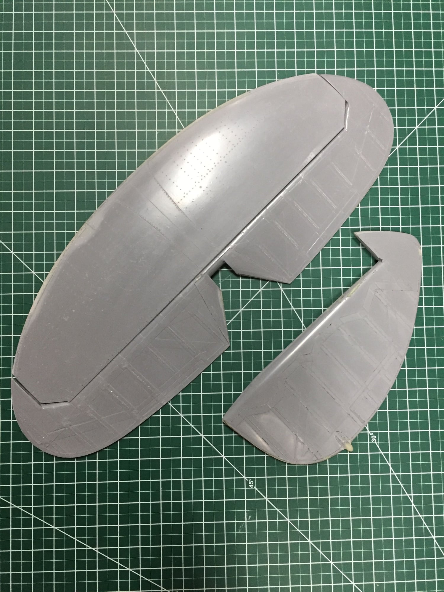
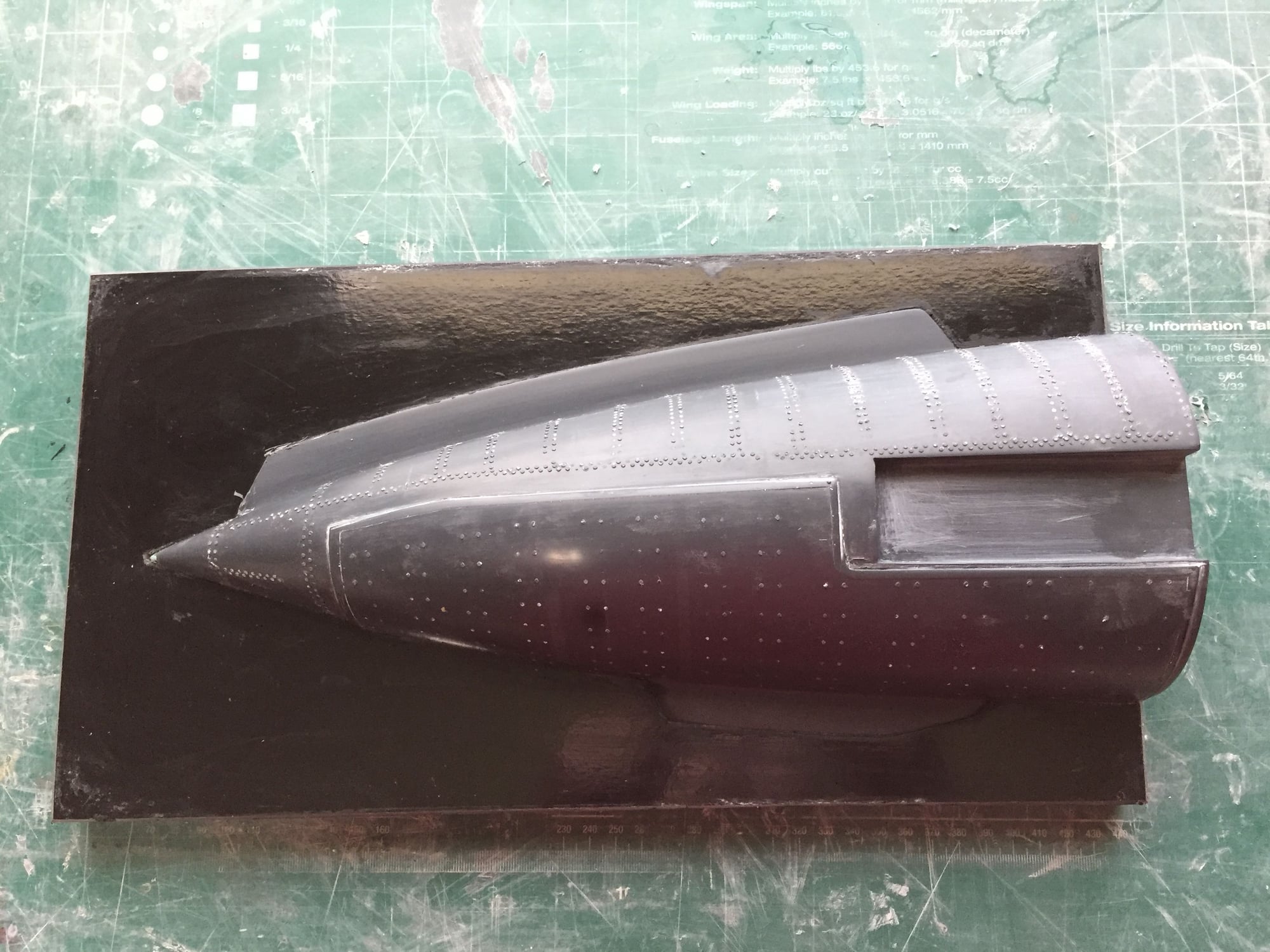
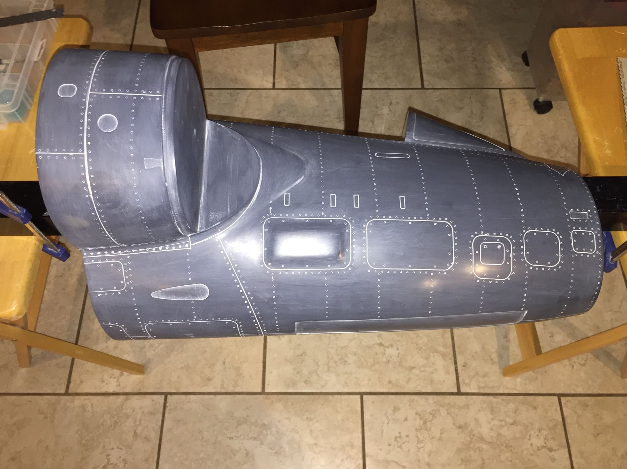
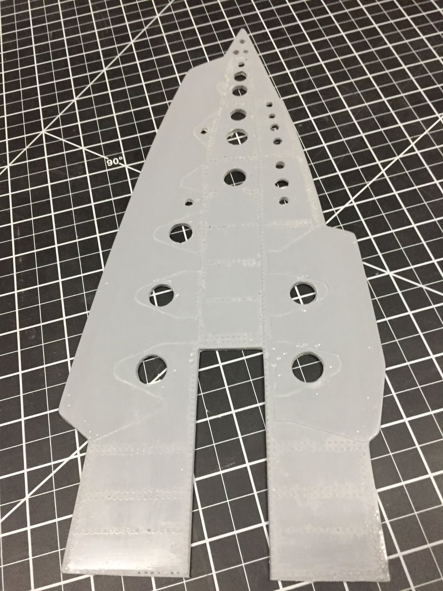
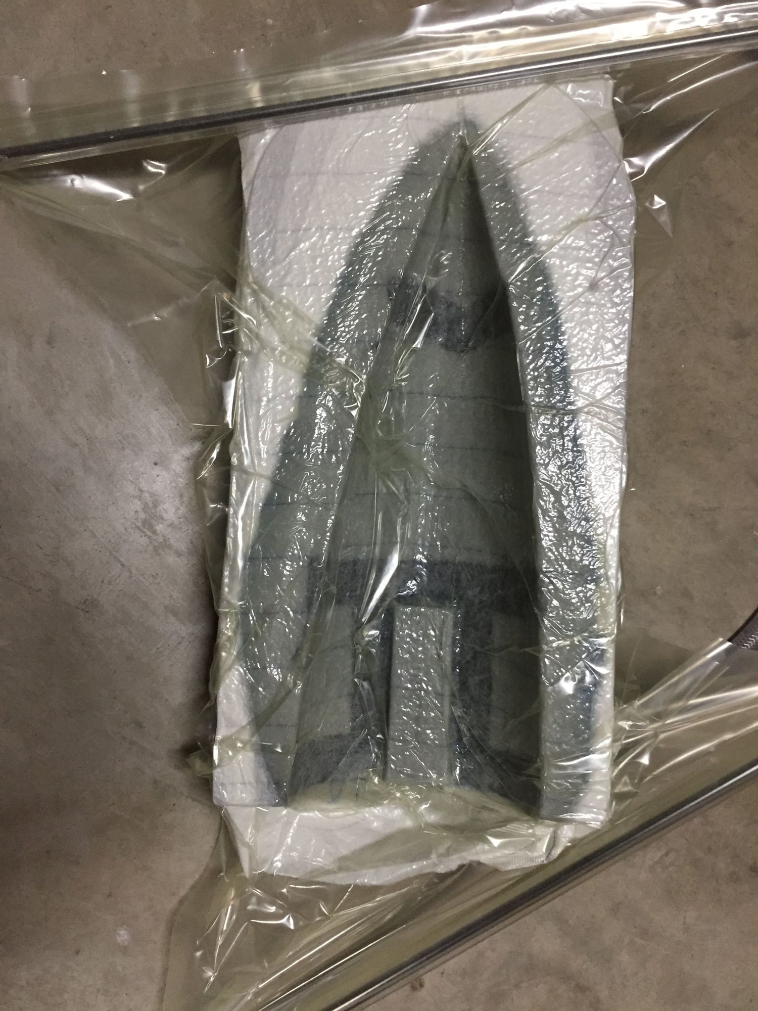
In between working on the speedbrake mold I have continued adding surface detail to the fuselage. This can be done in the house (and air conditioning) without annoying the wife too much.
I did find that I had to re-profile the dorsal spine behind the cockpit to match the sloping pressure bulkhead. After a deep breath I cut off part of the spine and faired it in. It now looks much better.
The forward fuselage is virtually ready to make the mold from.
Paul
I did find that I had to re-profile the dorsal spine behind the cockpit to match the sloping pressure bulkhead. After a deep breath I cut off part of the spine and faired it in. It now looks much better.
The forward fuselage is virtually ready to make the mold from.
Paul
08-16-2019, 05:55 PM
#291
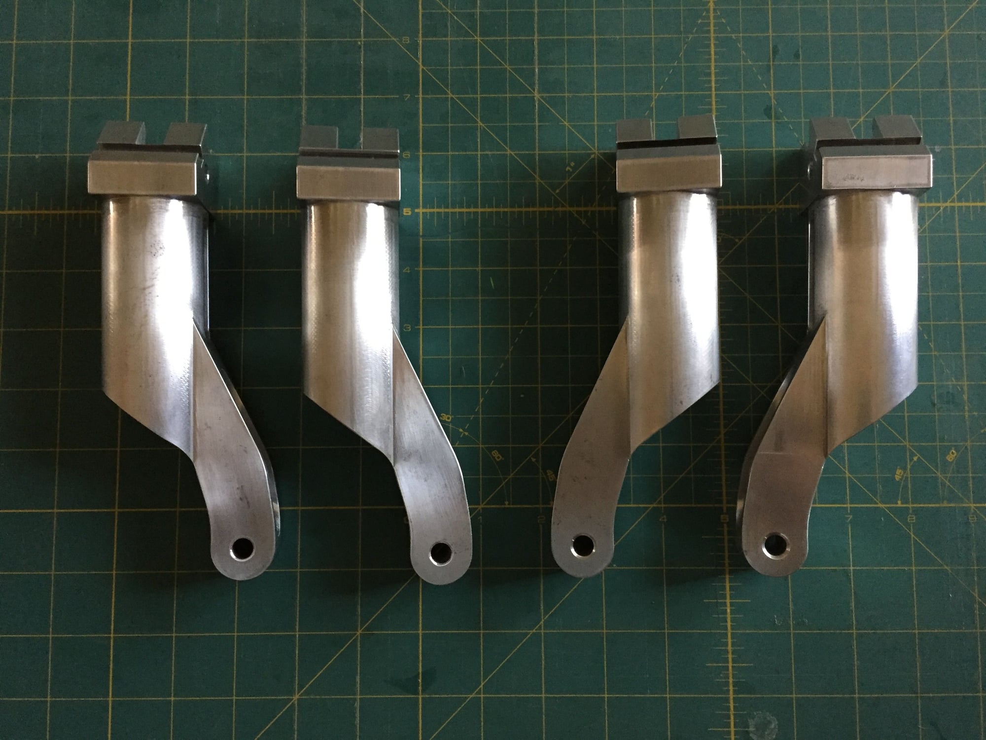
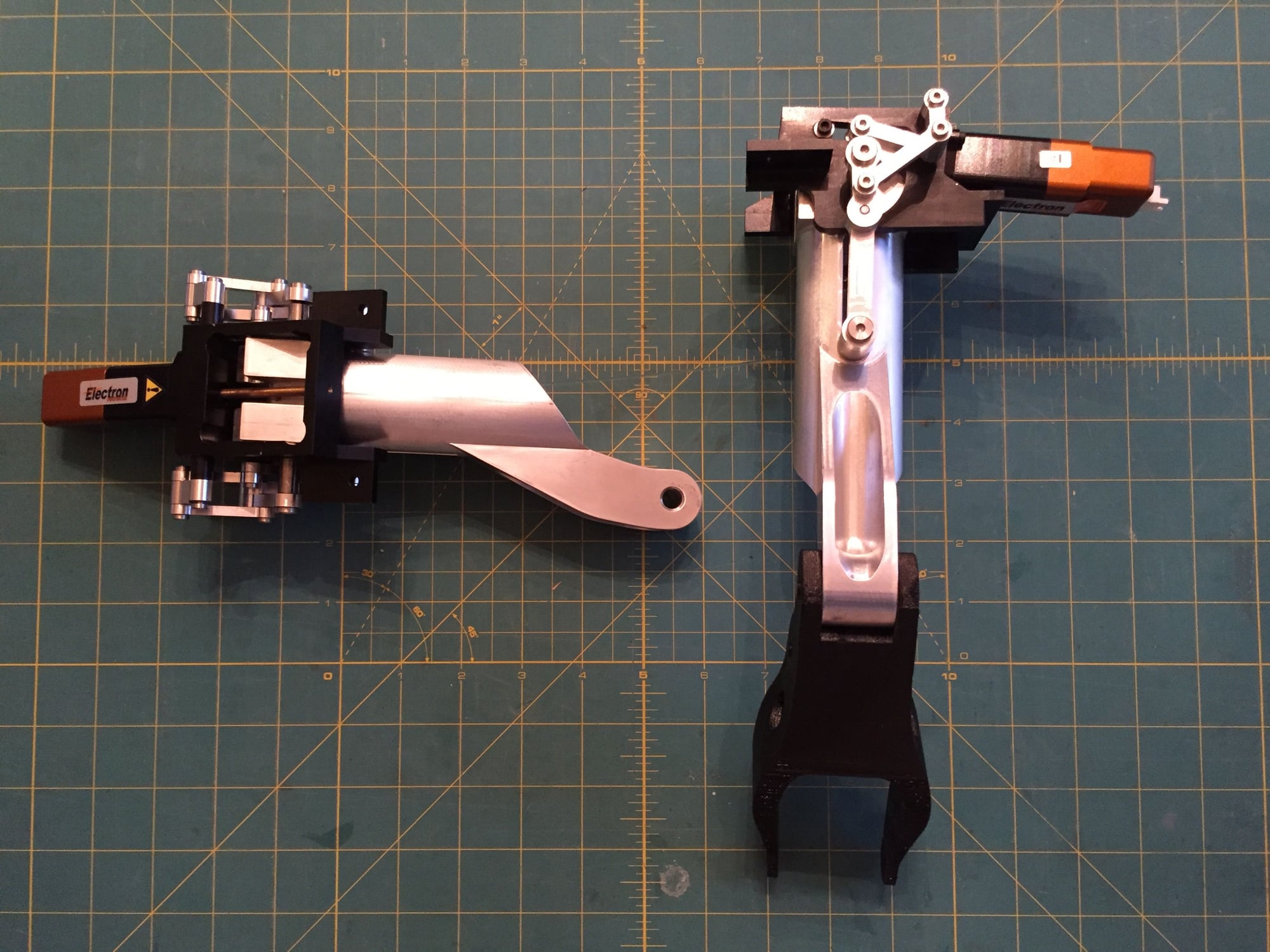
Today, more parts for the landing gear showed up. Each is one piece, machined from solid AL 7075. Amazing machining quality, but certainly not cheap. Very impressed with eMachineShop.
They were a simple drop in fit to the rest of the gear.
Just a few more parts to get and the main gear will be complete.
They were a simple drop in fit to the rest of the gear.
Just a few more parts to get and the main gear will be complete.
08-19-2019, 12:35 AM
#292
In between working on the speedbrake mold I have continued adding surface detail to the fuselage. This can be done in the house (and air conditioning) without annoying the wife too much.
I did find that I had to re-profile the dorsal spine behind the cockpit to match the sloping pressure bulkhead. After a deep breath I cut off part of the spine and faired it in. It now looks much better.
The forward fuselage is virtually ready to make the mold from.
Paul
I did find that I had to re-profile the dorsal spine behind the cockpit to match the sloping pressure bulkhead. After a deep breath I cut off part of the spine and faired it in. It now looks much better.
The forward fuselage is virtually ready to make the mold from.
Paul
08-19-2019, 05:55 PM
#293
Phil,
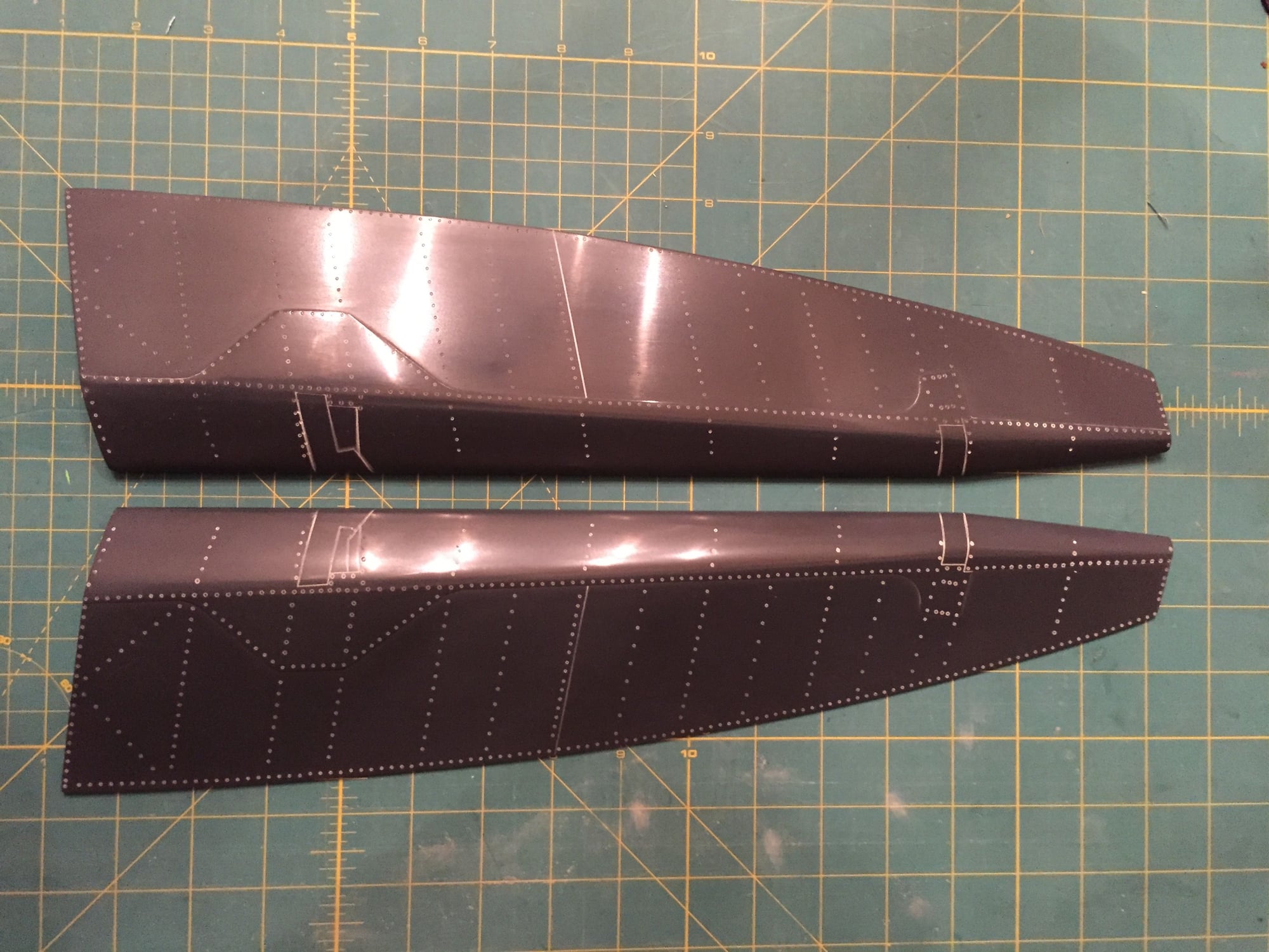
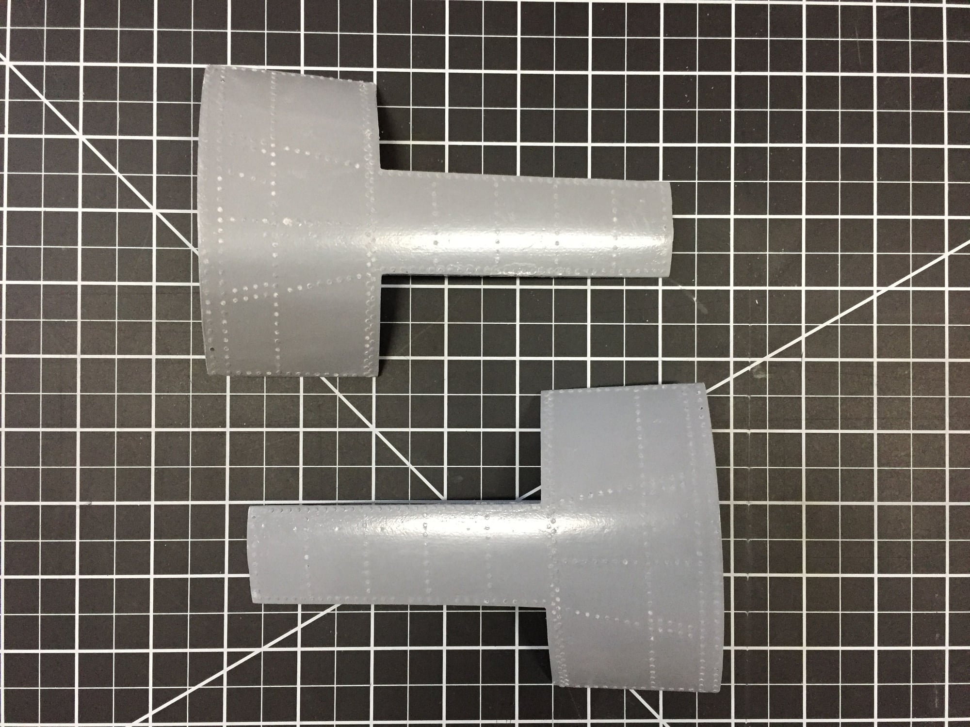
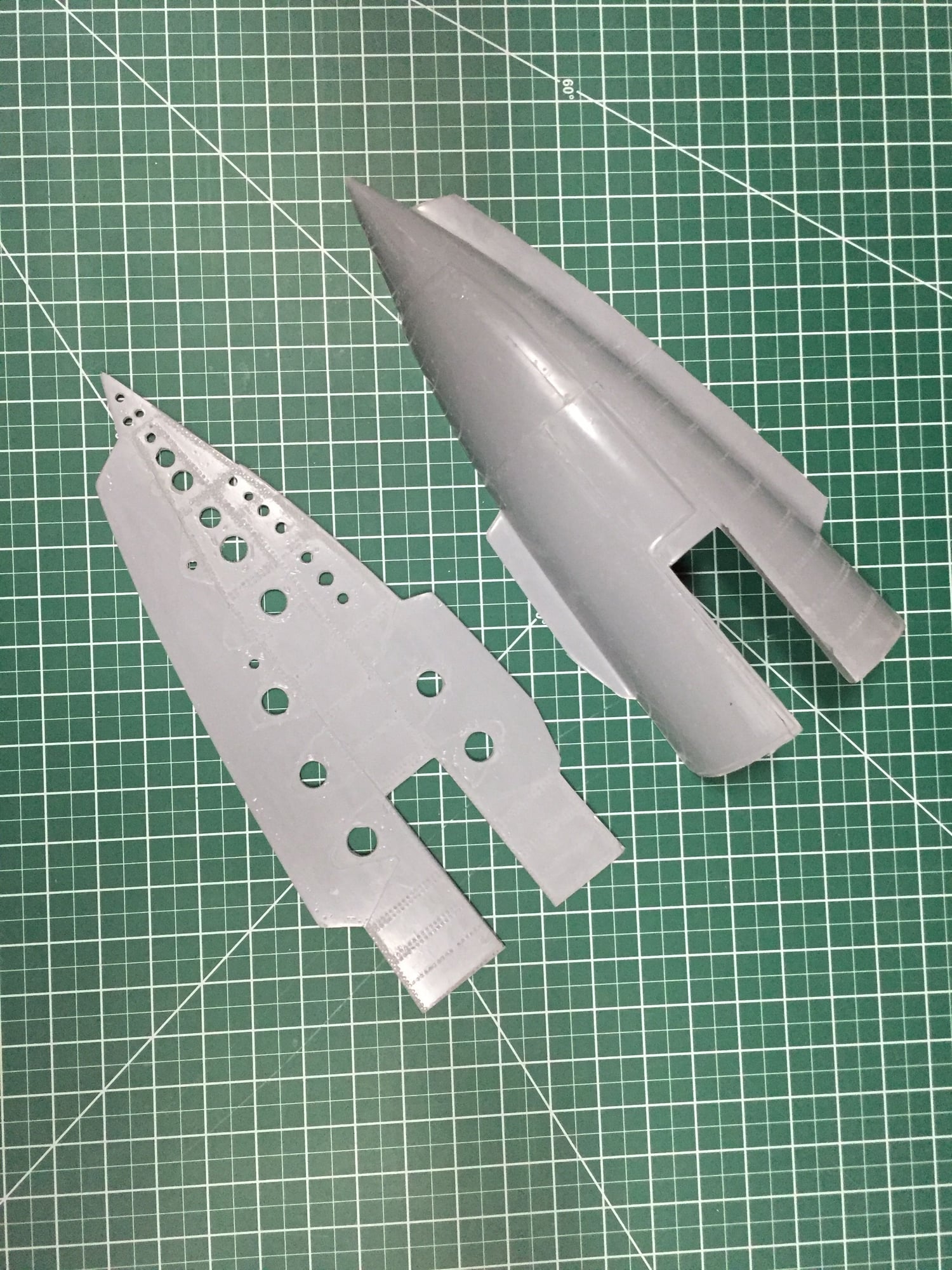
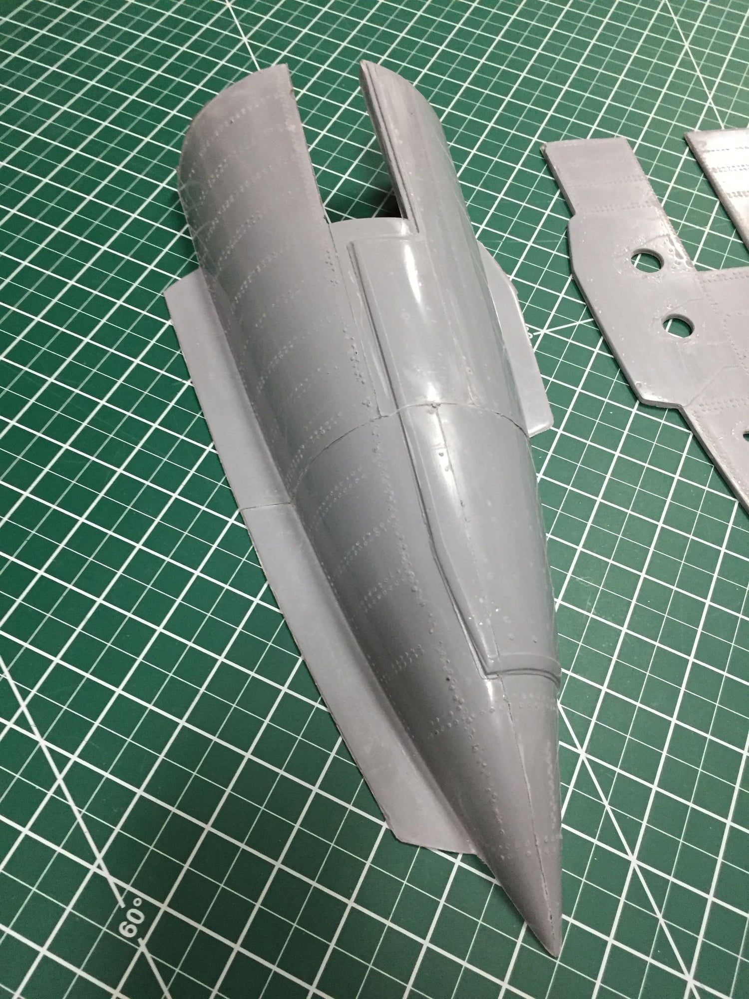
For the panel lines I use a hand engraving tool - 0.6mm wide, and scribe the lines with a few passes.
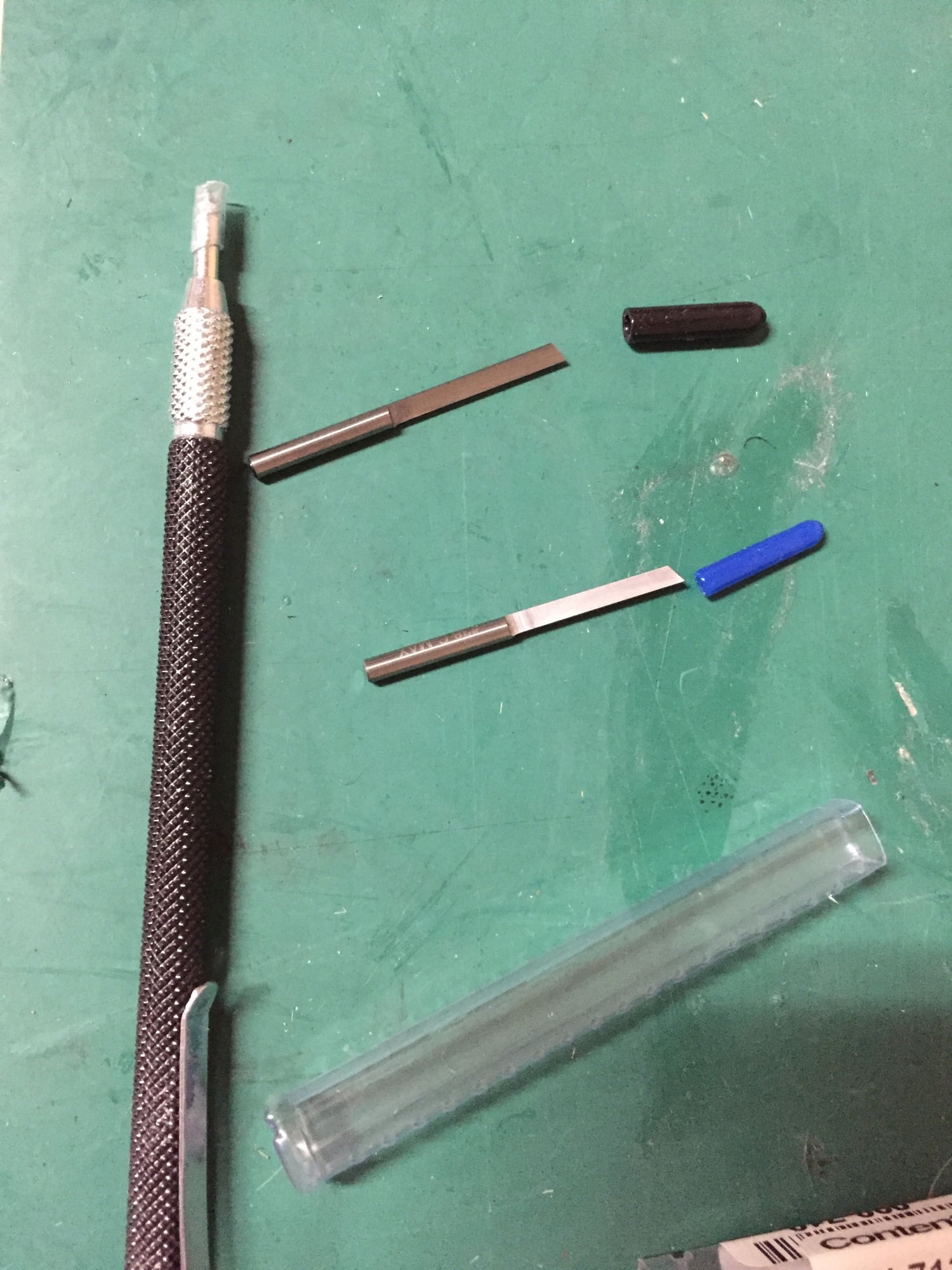
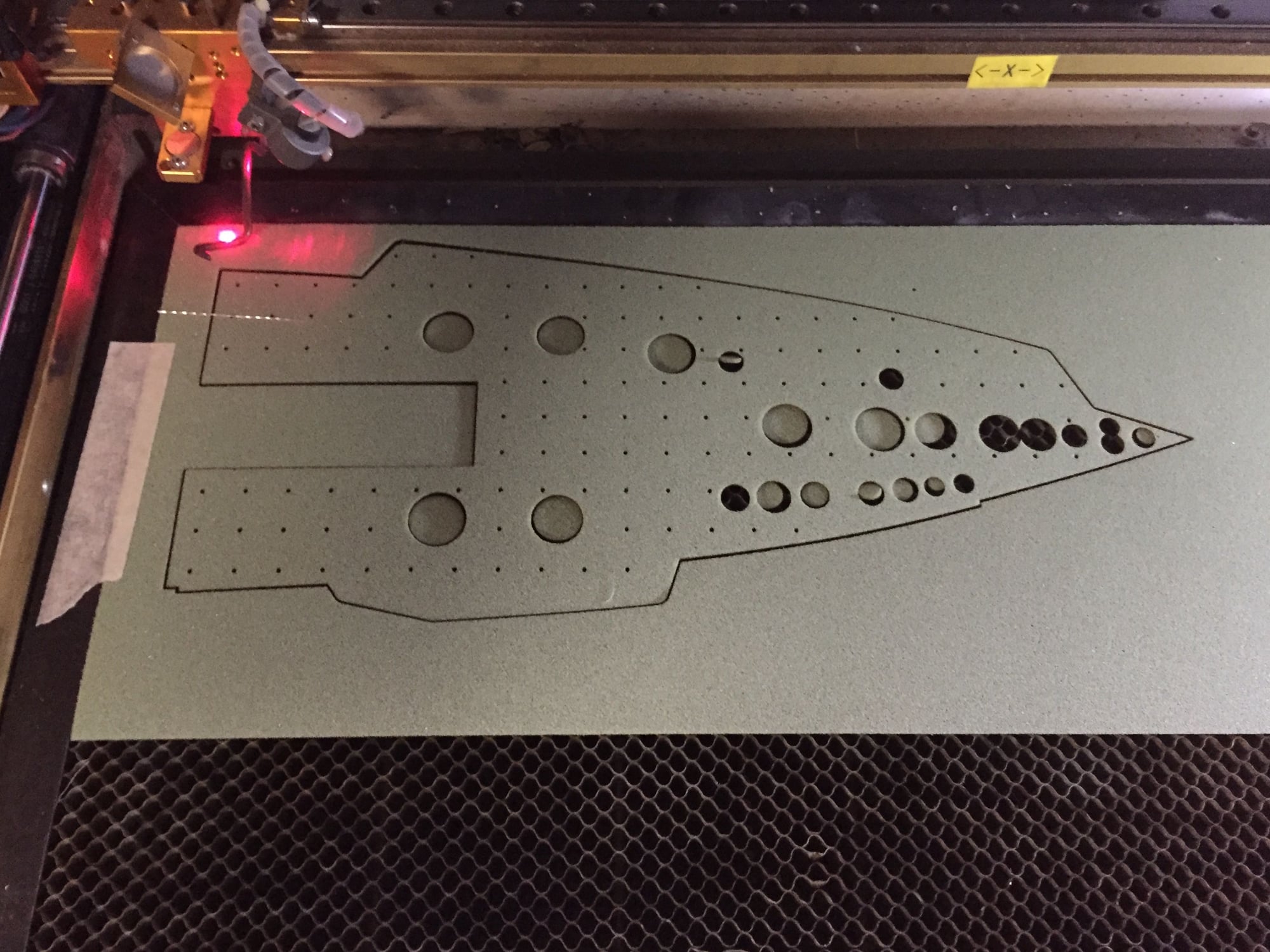
For a scribing guide, I laser cut the outline from sheets of plastic, about 0.6mm thick.
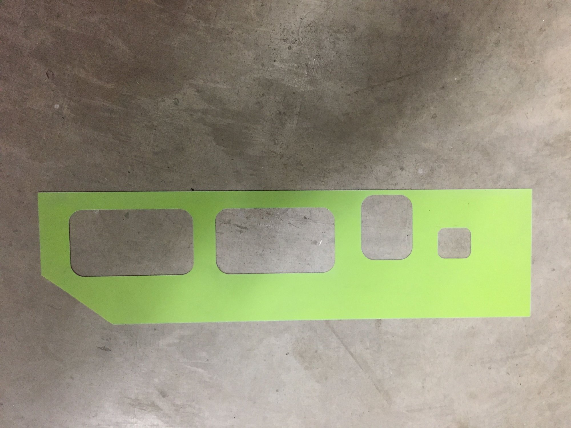
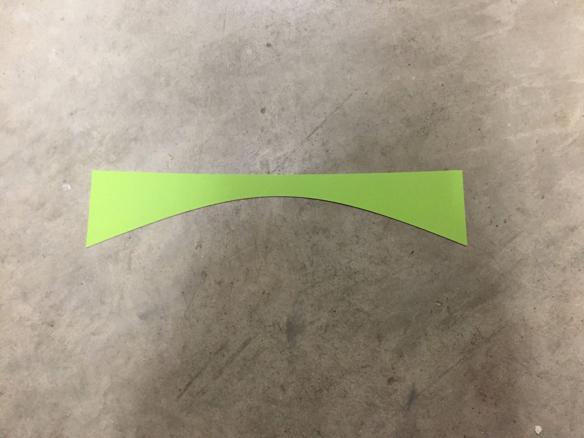
The curved piece above was used for the sloping panel line on the bottom of the forward fuselage. Taken from the CAD model with a sloping cut line, it was un-rolled into a flat surface to give the correct shape.
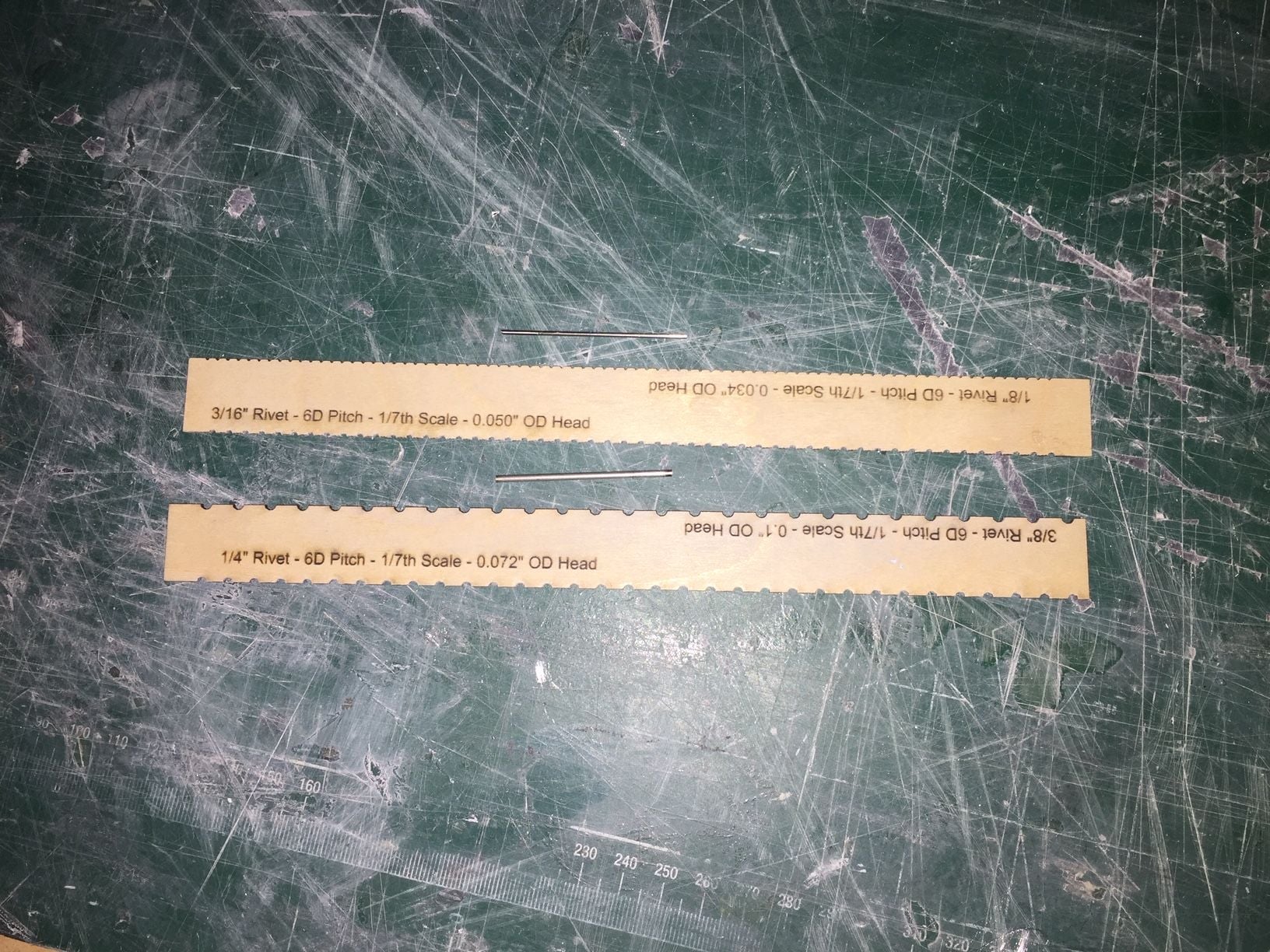
For the rivets, I am using pieces of hypodermic tube of the correct diameter in a Dremel drill. I laser cut a rivet guide in a couple of sizes out of 16" plywood. Just a light touch on slow speed is all that is required to make a clean rivet mark.
Paul
For the panel lines I use a hand engraving tool - 0.6mm wide, and scribe the lines with a few passes.
For a scribing guide, I laser cut the outline from sheets of plastic, about 0.6mm thick.
The curved piece above was used for the sloping panel line on the bottom of the forward fuselage. Taken from the CAD model with a sloping cut line, it was un-rolled into a flat surface to give the correct shape.
For the rivets, I am using pieces of hypodermic tube of the correct diameter in a Dremel drill. I laser cut a rivet guide in a couple of sizes out of 16" plywood. Just a light touch on slow speed is all that is required to make a clean rivet mark.
Paul
08-23-2019, 06:57 AM
#294
Have made progress on a couple of fronts.
After using a friends mini lathe to make some parts, I bought one, as I could see many uses for it. I got a 7"x16" mini lathe from LittleMachineShop.com
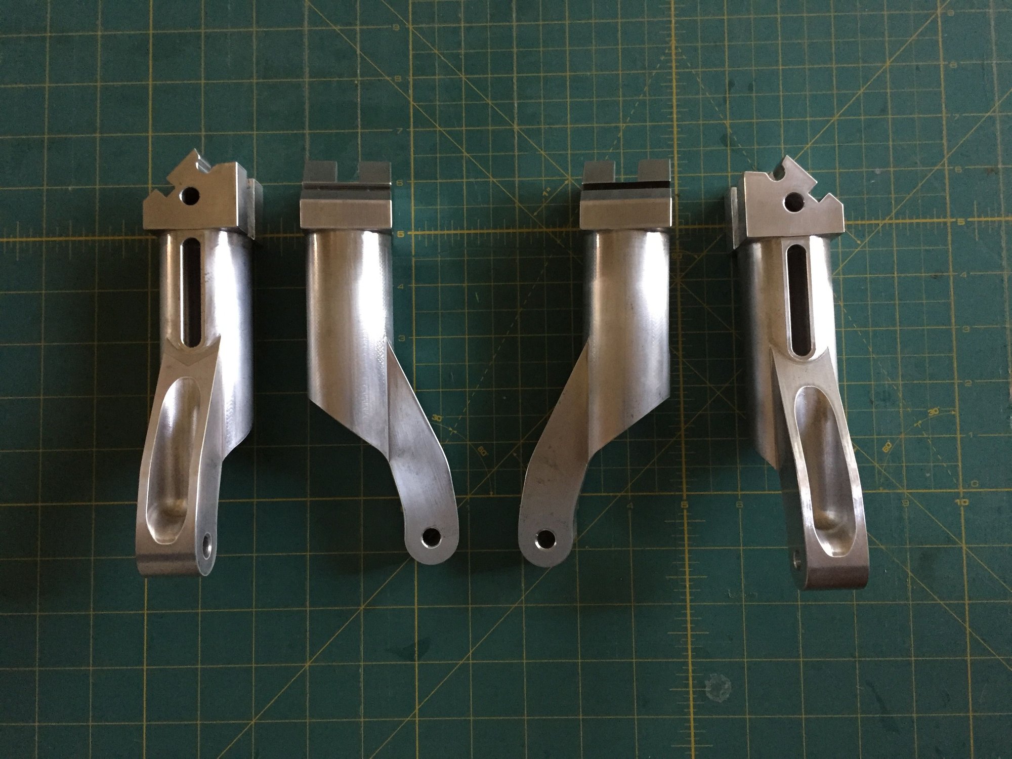
Initial parts made are the shock struts for the Buccaneer. With a notional 50lb weight target, that's just under 25lb per main wheel, and the lever arm is 3.4:1 between the wheel and the shock strut, so static load on the shock strut is going to be over 75lb. I found a spring of the appropriate diameter (15mm) with a maximum compression load of 165lb which should accommodate any less than gentle landings.
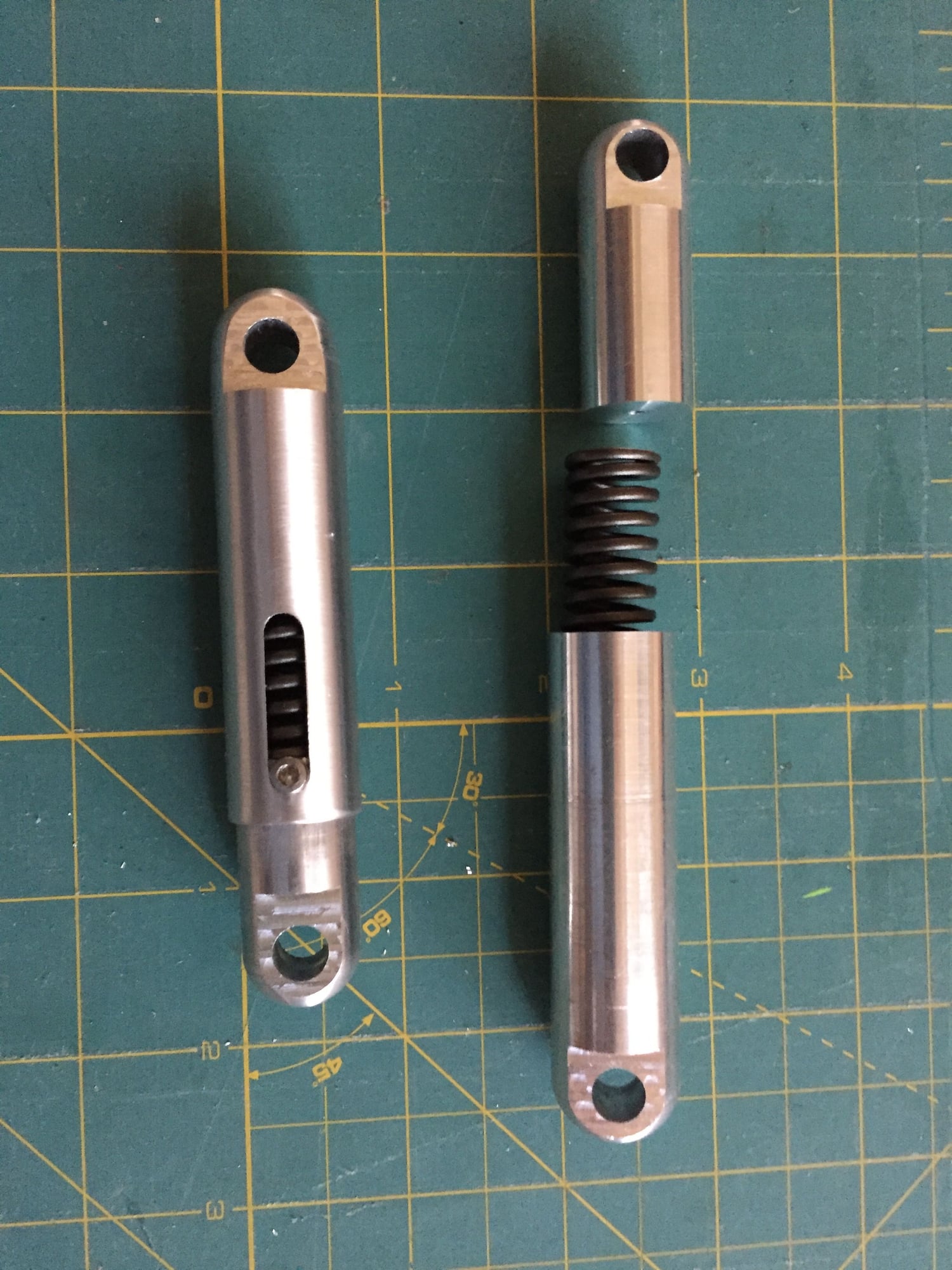
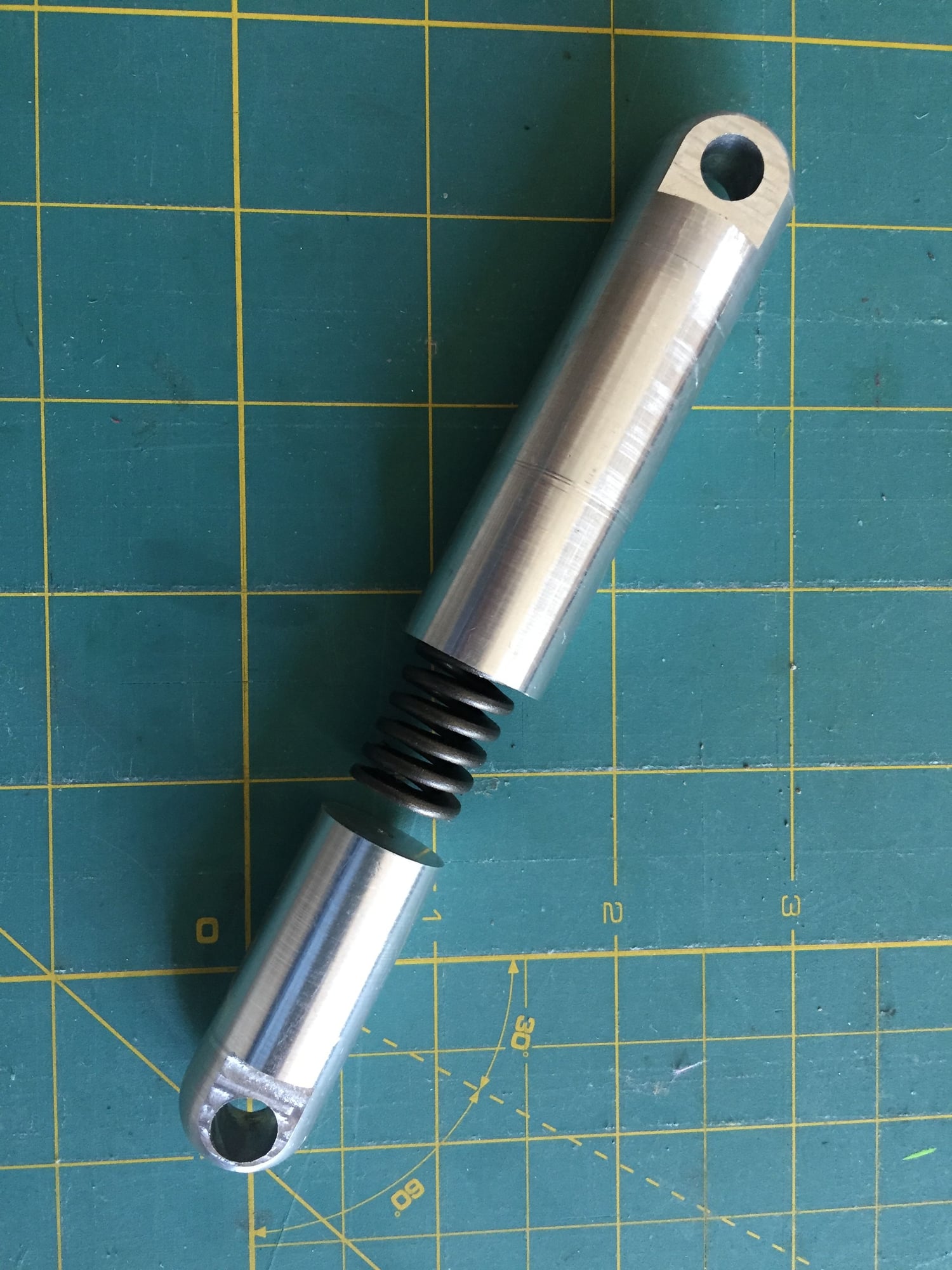
Max travel is just under 10mm. That is less than desired, so after building these and proving the design concept, I re-worked the CAD file for the gear and re-did the design for the shock strut. v2 will get 24mm of travel. These initial ones will work during the build and I will make the new version before I fly it.
Paul
After using a friends mini lathe to make some parts, I bought one, as I could see many uses for it. I got a 7"x16" mini lathe from LittleMachineShop.com
Initial parts made are the shock struts for the Buccaneer. With a notional 50lb weight target, that's just under 25lb per main wheel, and the lever arm is 3.4:1 between the wheel and the shock strut, so static load on the shock strut is going to be over 75lb. I found a spring of the appropriate diameter (15mm) with a maximum compression load of 165lb which should accommodate any less than gentle landings.
Max travel is just under 10mm. That is less than desired, so after building these and proving the design concept, I re-worked the CAD file for the gear and re-did the design for the shock strut. v2 will get 24mm of travel. These initial ones will work during the build and I will make the new version before I fly it.
Paul
08-23-2019, 07:02 AM
#295
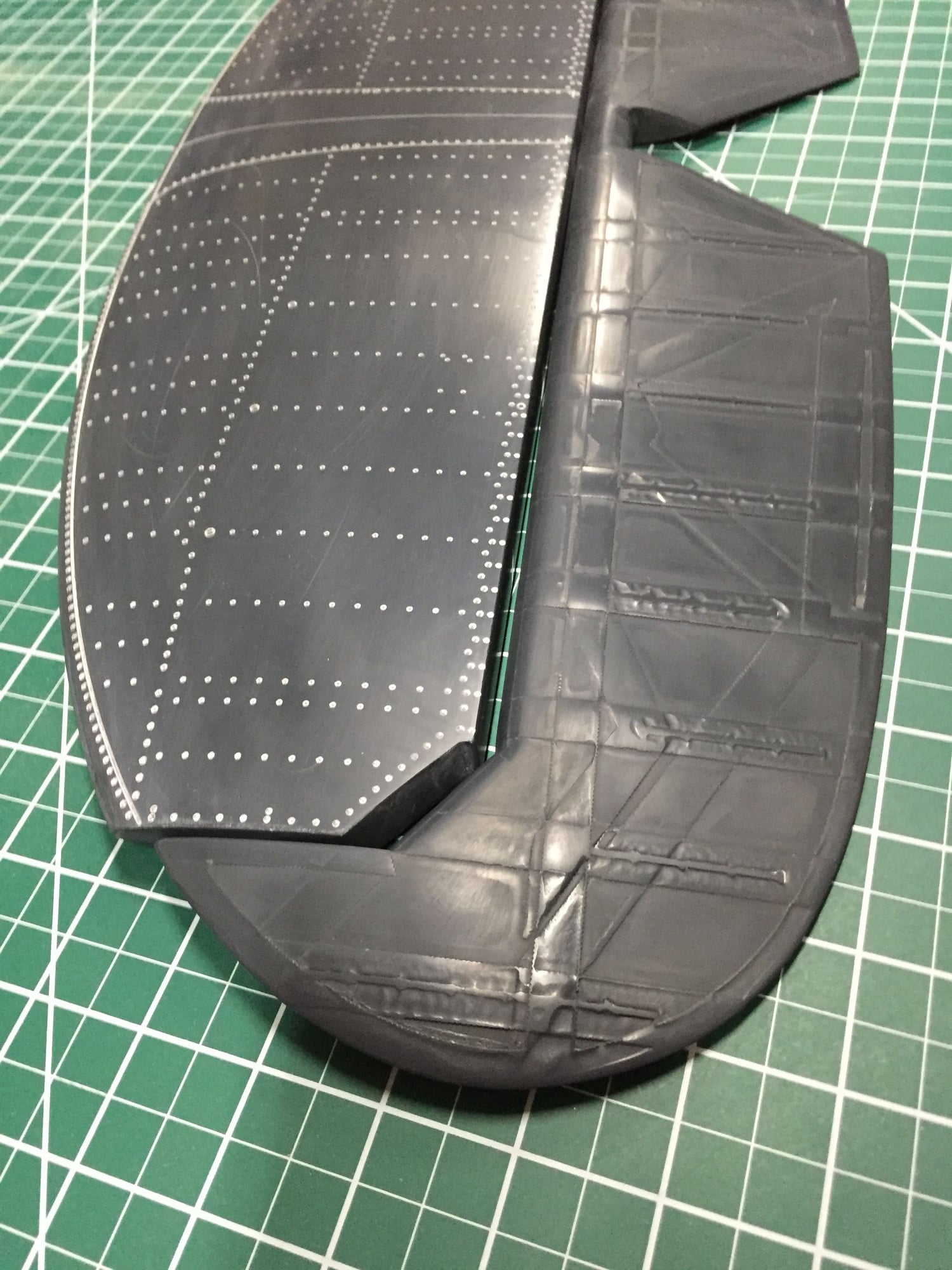
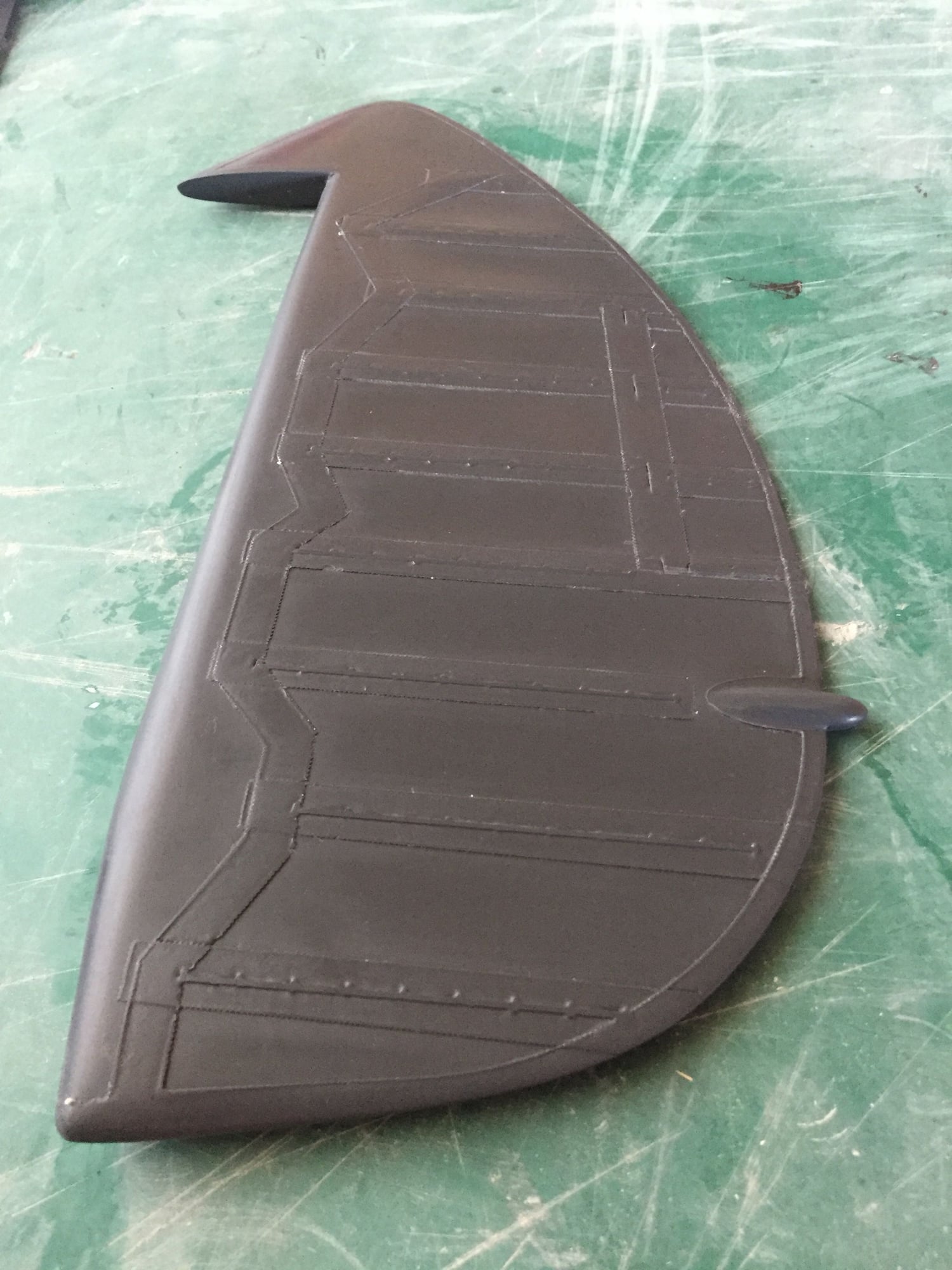
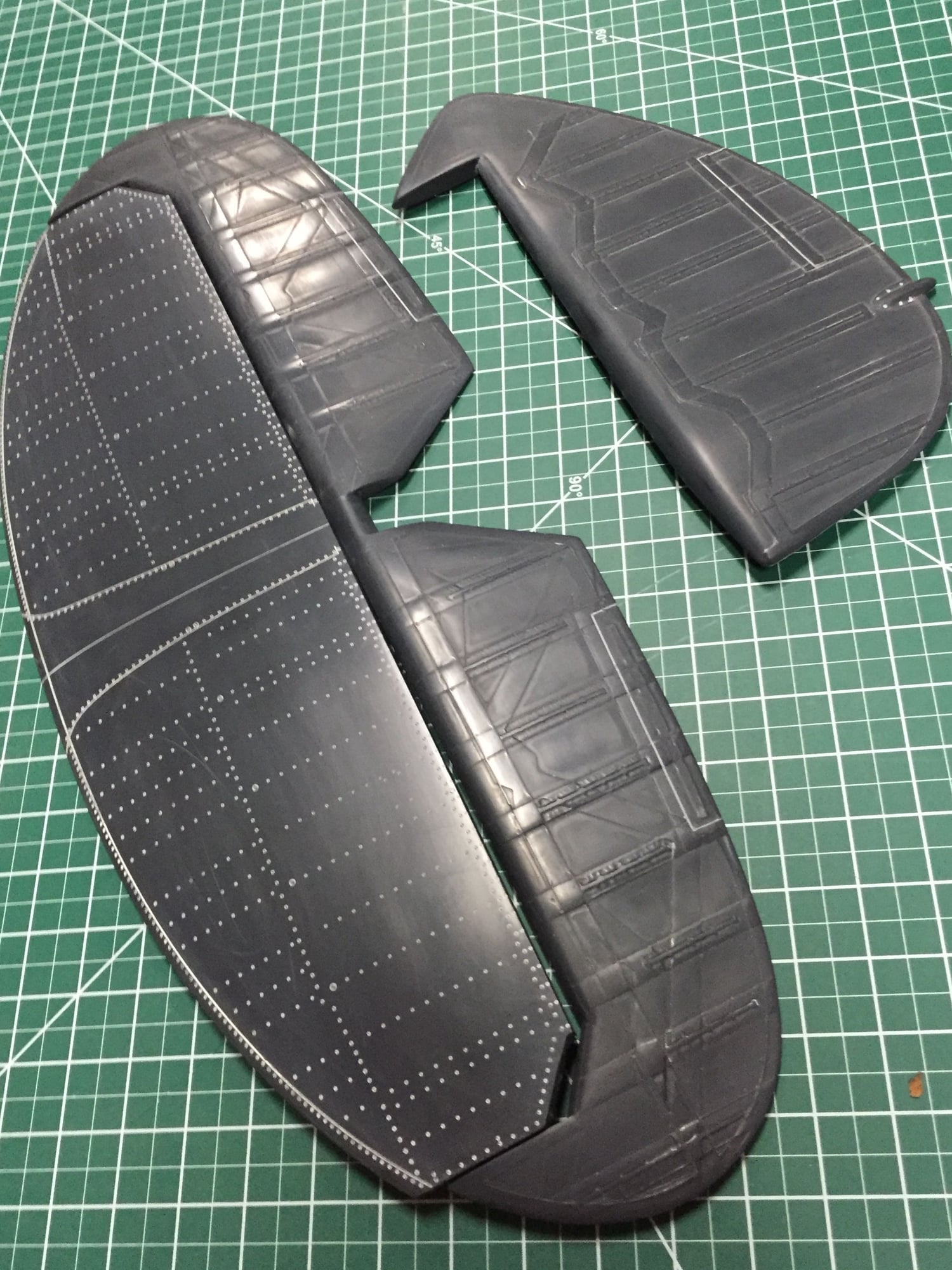
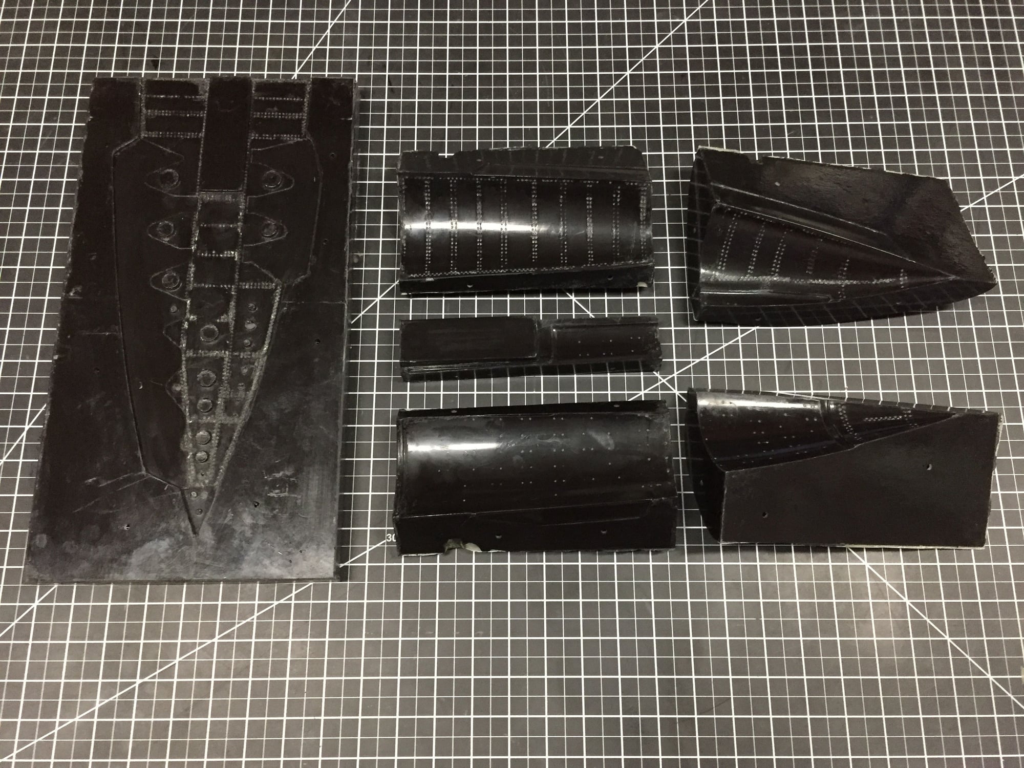
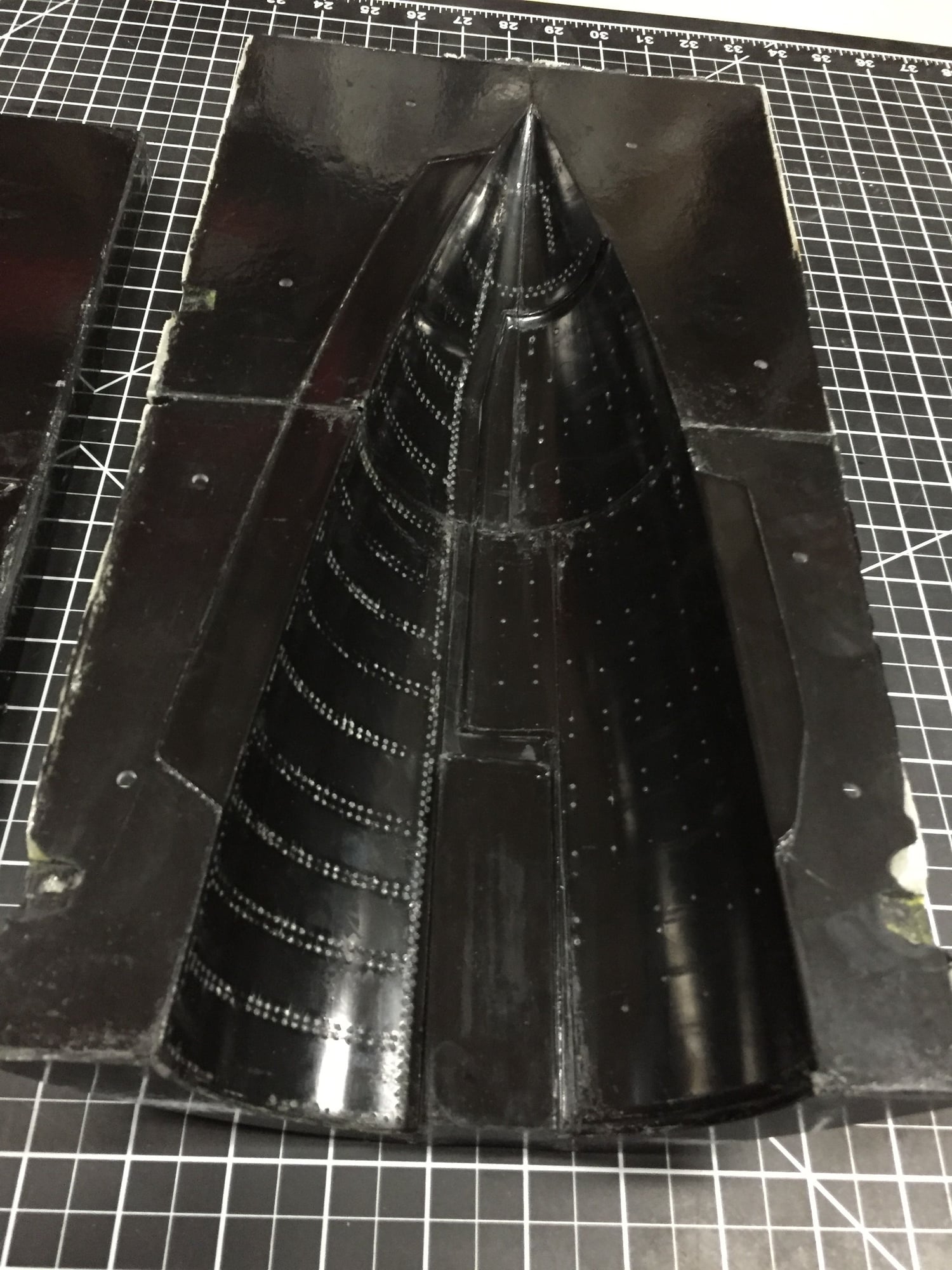
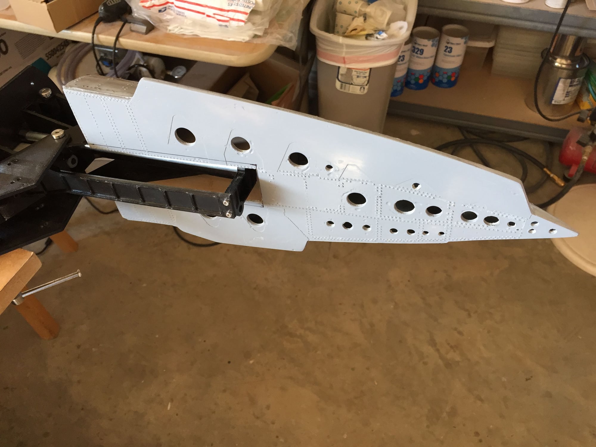
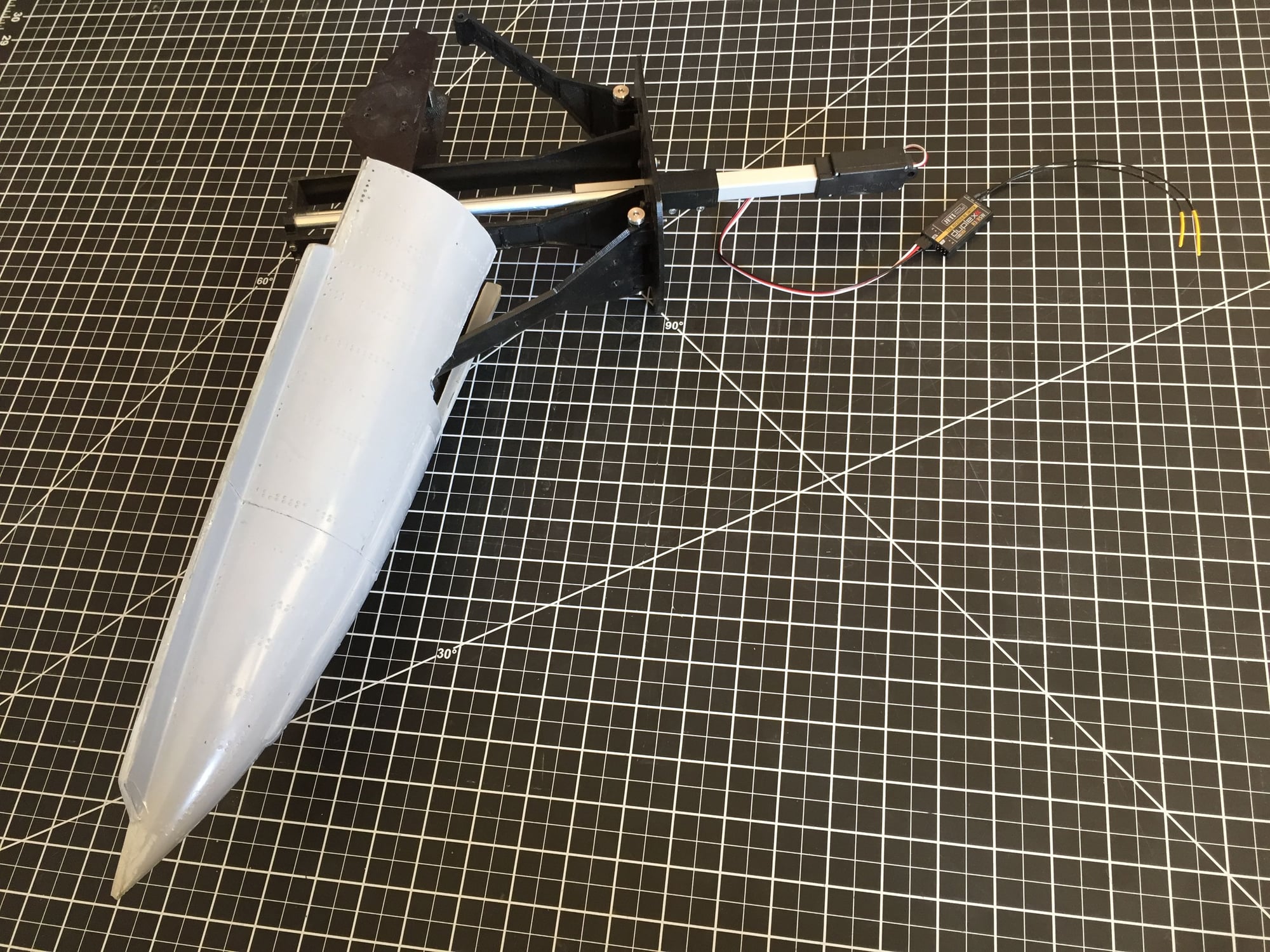
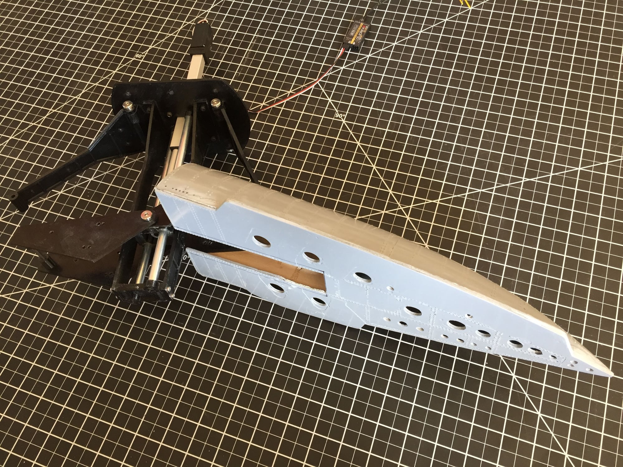
Another bit of progress has been with the speedbrake. Following the complete failure of the first mold, I redid the plugs and pulled a good set of molds for the right hand speedbrake. I laid up the speedbrake and fitted the internal structure.
I found a couple of design issues once I assembled it onto the actuation mechanism, but easily overcome and I'll correct the design for the left hand part.
Paul
I found a couple of design issues once I assembled it onto the actuation mechanism, but easily overcome and I'll correct the design for the left hand part.
Paul
 08-23-2019, 08:13 AM
#298
Dave,
As shown (with just one half of the speedbrake) it weighs 1lb 6oz. Probably around 1lb 10oz with both.
I plan to change the 2 rods from steel to AL to save a bit. Maybe an ounce or 2.
If I get some of the parts machined from AL, it will get heavier, as AL is twice the density of the PETG I used to 3D print the parts.
Paul
 08-23-2019, 01:00 PM
#300
Dave,
As shown (with just one half of the speedbrake) it weighs 1lb 6oz. Probably around 1lb 10oz with both.
I plan to change the 2 rods from steel to AL to save a bit. Maybe an ounce or 2.
If I get some of the parts machined from AL, it will get heavier, as AL is twice the density of the PETG I used to 3D print the parts.
Paul
As shown (with just one half of the speedbrake) it weighs 1lb 6oz. Probably around 1lb 10oz with both.
I plan to change the 2 rods from steel to AL to save a bit. Maybe an ounce or 2.
If I get some of the parts machined from AL, it will get heavier, as AL is twice the density of the PETG I used to 3D print the parts.
Paul