


Juniaer K45TP Tucano from Brazil?


 09-21-2022, 10:02 PM
#203
Senior Member
 09-21-2022, 10:05 PM
#204
Senior Member
09-22-2022, 02:08 AM
#205
09-28-2022, 06:28 AM
#207
Senior Member
Thanks Didier, appreciate your time to answer my question. So the only way to cool the engine down is to use a blower as i understand that taping the cowling with heat resistance tape will only protect the cowling but not cooling the turbine. Please correct me if I’m wrong. Regards
 09-28-2022, 06:39 AM
#209
Senior Member
09-28-2022, 06:46 AM
#210
Senior Member
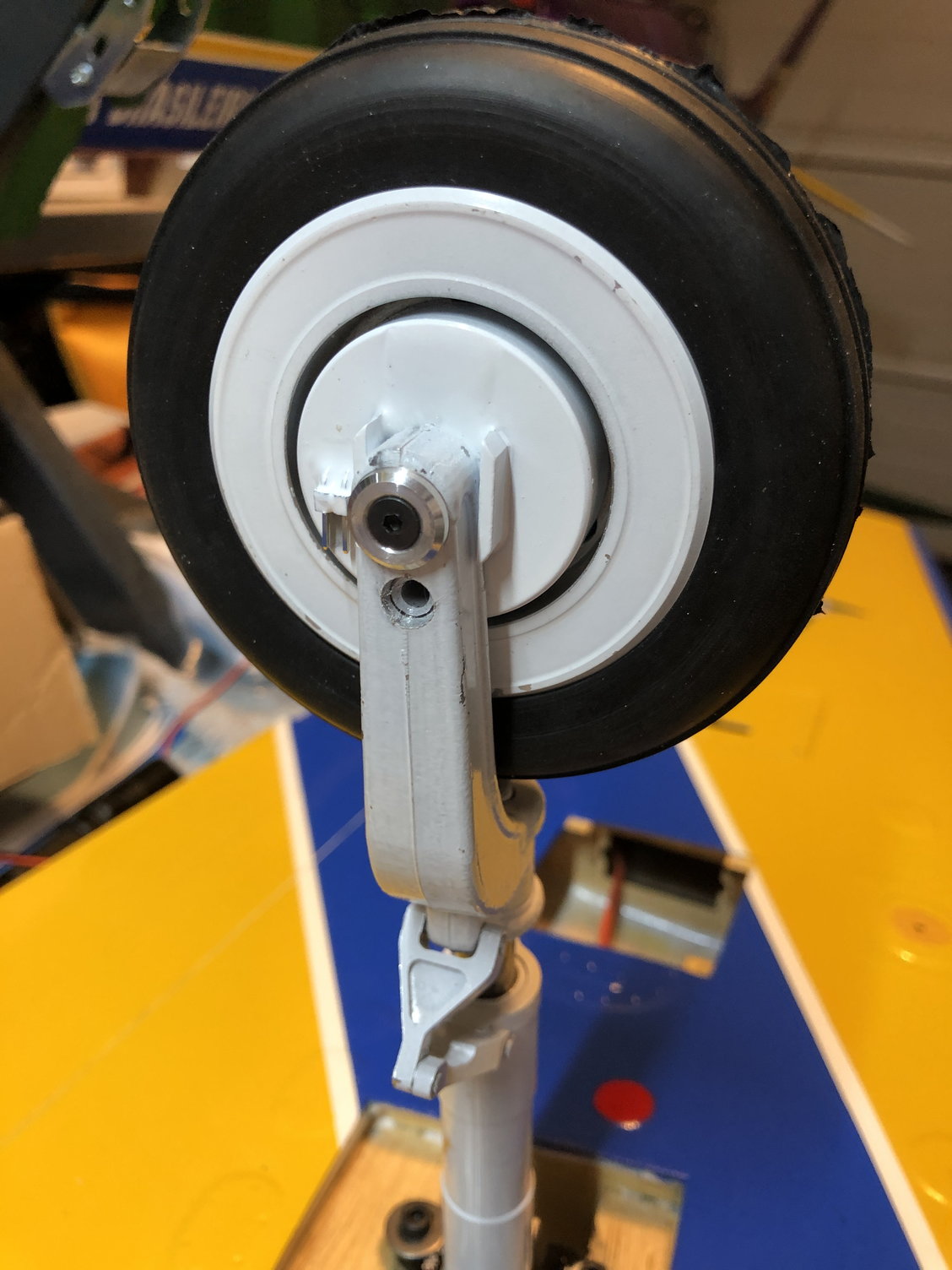
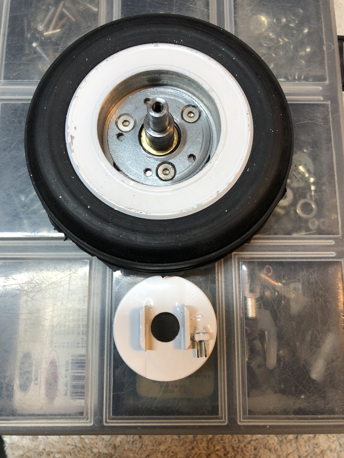
I removed material of the tabs of the brakes by milling (after this painted the brakes white). The disks are screwed in the wheels. The brakes are "floating" on the axis.
Hope this help.

 09-29-2022, 12:39 AM
#214
Senior Member
09-30-2022, 02:54 AM
#216
Senior Member
09-30-2022, 12:20 PM
#217

My Feedback: (50)
i made a fiberglass fuel tank 1850 ml that fits between the wing tube and the nose steering servo the stock tanks did not fit between the steering servo and the wing spar tube
as shown in the manual also was too small for my liking,
also converted my brakes to electric
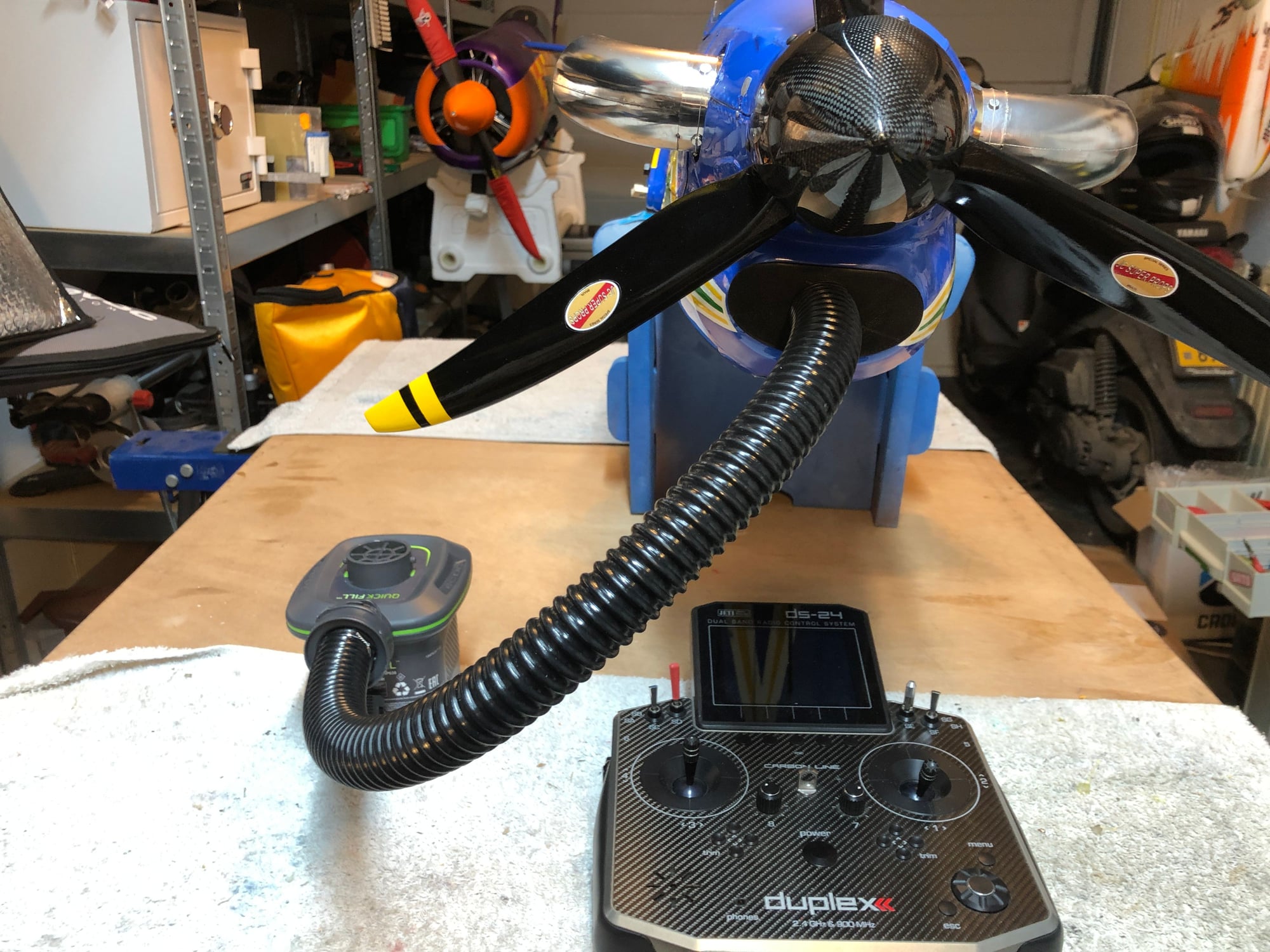
using a 22x12 3 blade with a xicoy tp45 just waiting on servo multi lead connectors to tidy up wiring to wings
as shown in the manual also was too small for my liking,
also converted my brakes to electric
using a 22x12 3 blade with a xicoy tp45 just waiting on servo multi lead connectors to tidy up wiring to wings
10-15-2022, 02:34 PM
#218

Hi Guys,
Sorry to be "late to the party". I bought one of these Tucanos in the summer of 2019 (which was before this thread was created). I built the plane in the winter of 2019-2020 and first flew it in spring of 2020. A buddy told me about this thread and asked me to post pics and build thoughts. Hopefully, someone will find this info useful. These items aren't in any particular order.
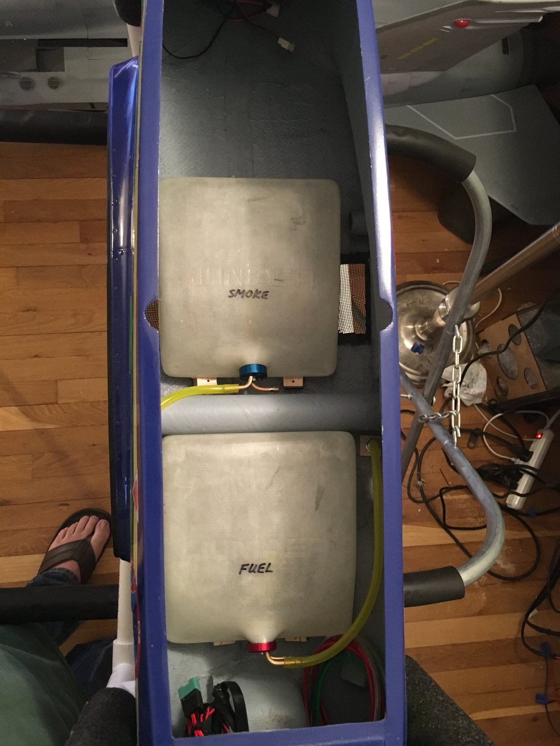
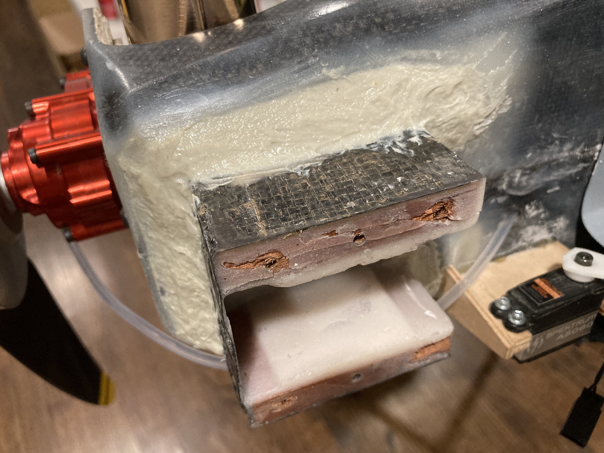
Fuel & Smoke Tanks
The kit comes with two identical tanks (one for fuel and one for smoke). As I recall, they are about 50 oz each. 50 oz is a bit marginal (but doable) for a 45 size turbine but having a bit more fuel is nice, and having 50 oz of smoke is way overkill. Normally, most planes would have about 20-25 oz.
First thing was locating the tanks in the fuselage and determining how they would mount.

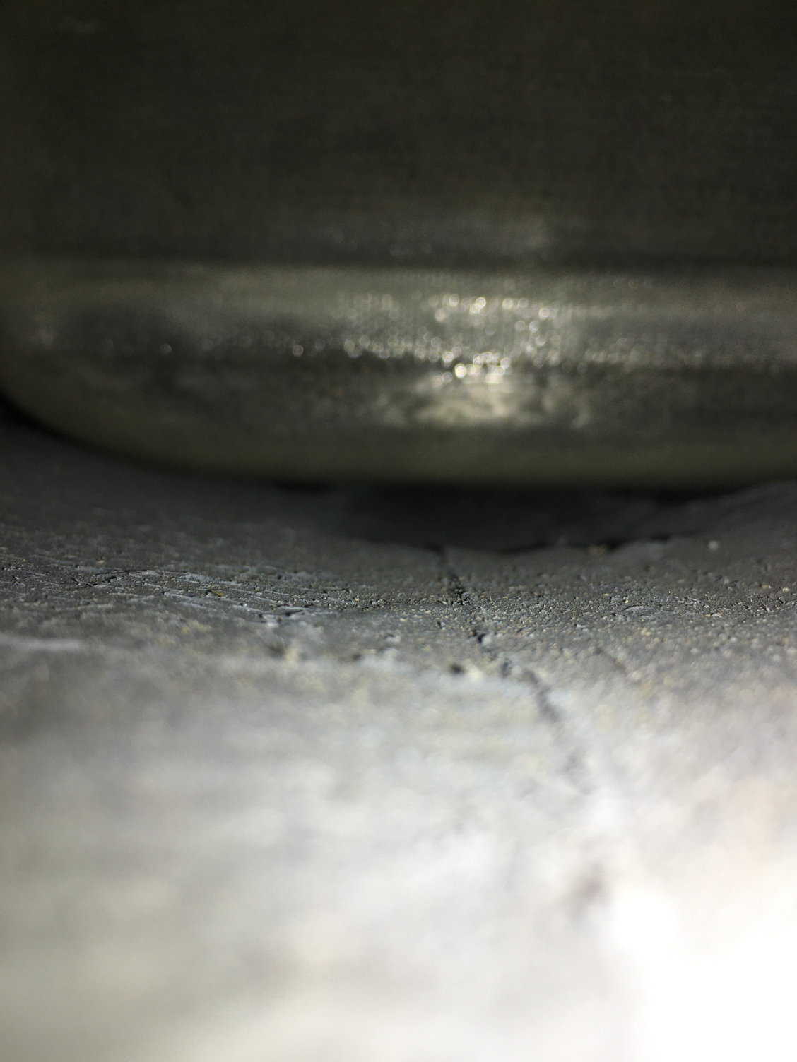
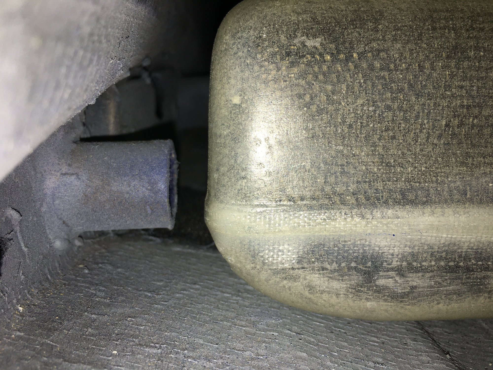
As you can see, there isn't a lot of room around or under the tanks nor any particularly good mounting points. As such, I decided to Hysol hardwood blocks to the front and rear of each tank, drill a hole through them, and screw (from the outside of the fuselage belly) a #2 screw to mount the tanks. This has work great for three years and the tanks have been secure and there hasn't been any cracking of the fuselage belly fiberglass.
Regards,
Jim
Sorry to be "late to the party". I bought one of these Tucanos in the summer of 2019 (which was before this thread was created). I built the plane in the winter of 2019-2020 and first flew it in spring of 2020. A buddy told me about this thread and asked me to post pics and build thoughts. Hopefully, someone will find this info useful. These items aren't in any particular order.
Fuel & Smoke Tanks
The kit comes with two identical tanks (one for fuel and one for smoke). As I recall, they are about 50 oz each. 50 oz is a bit marginal (but doable) for a 45 size turbine but having a bit more fuel is nice, and having 50 oz of smoke is way overkill. Normally, most planes would have about 20-25 oz.
First thing was locating the tanks in the fuselage and determining how they would mount.
As you can see, there isn't a lot of room around or under the tanks nor any particularly good mounting points. As such, I decided to Hysol hardwood blocks to the front and rear of each tank, drill a hole through them, and screw (from the outside of the fuselage belly) a #2 screw to mount the tanks. This has work great for three years and the tanks have been secure and there hasn't been any cracking of the fuselage belly fiberglass.
Regards,
Jim
The following users liked this post:
shrek514 (10-15-2022)
10-15-2022, 02:52 PM
#219
"Combi" Tank
As you can see in the photos above, the smoke tank partially obstructs the vents on either side of the belly. I also thought that using the stock setup gives you too much smoke and too little fuel. As such, I decided to convert the rear tank to a "combi" tank carrying both smoke and fuel. I also cut out about 3/4" of the width of the tank to make the tank narrower to allow the vents to breath better.
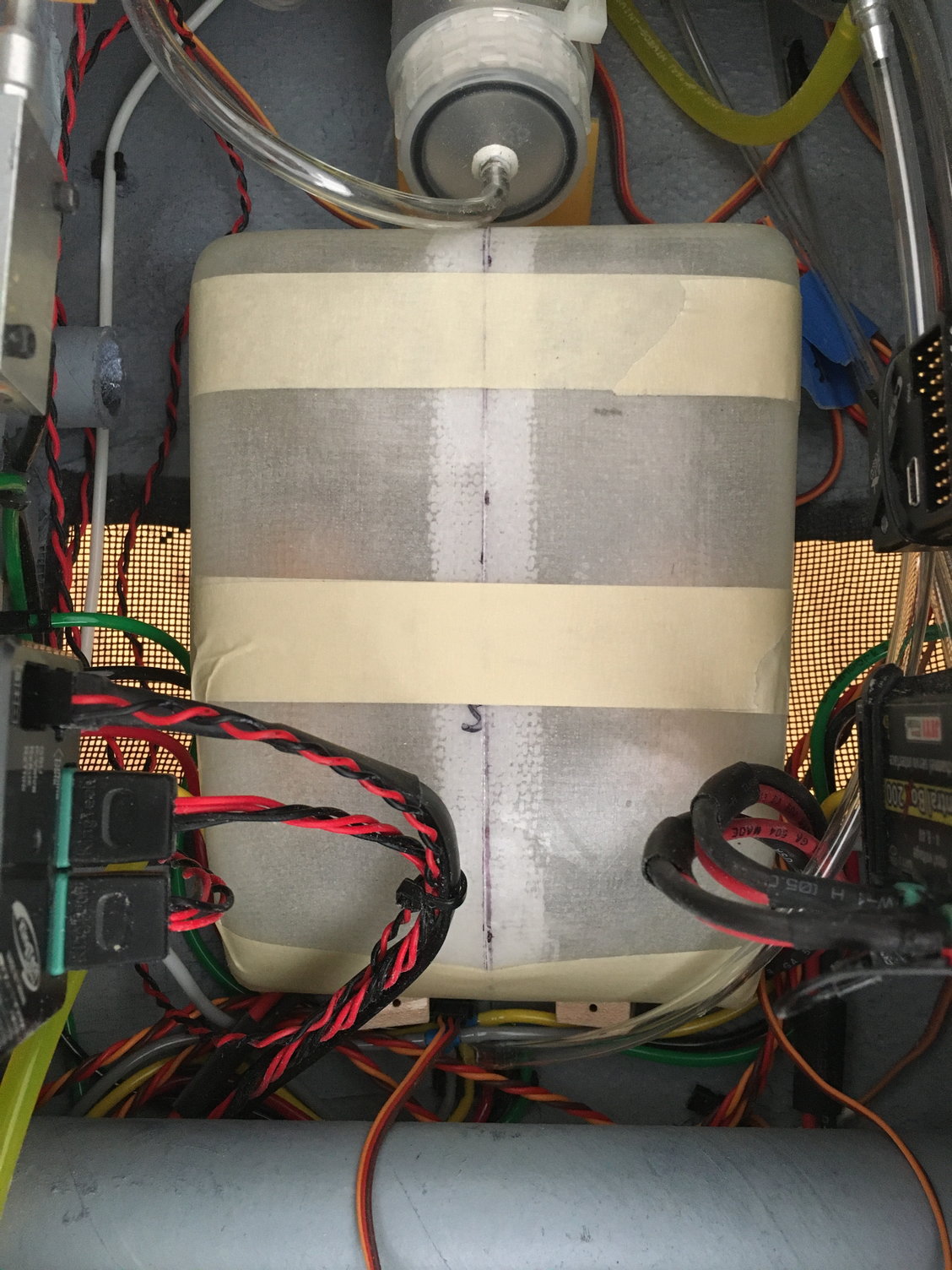
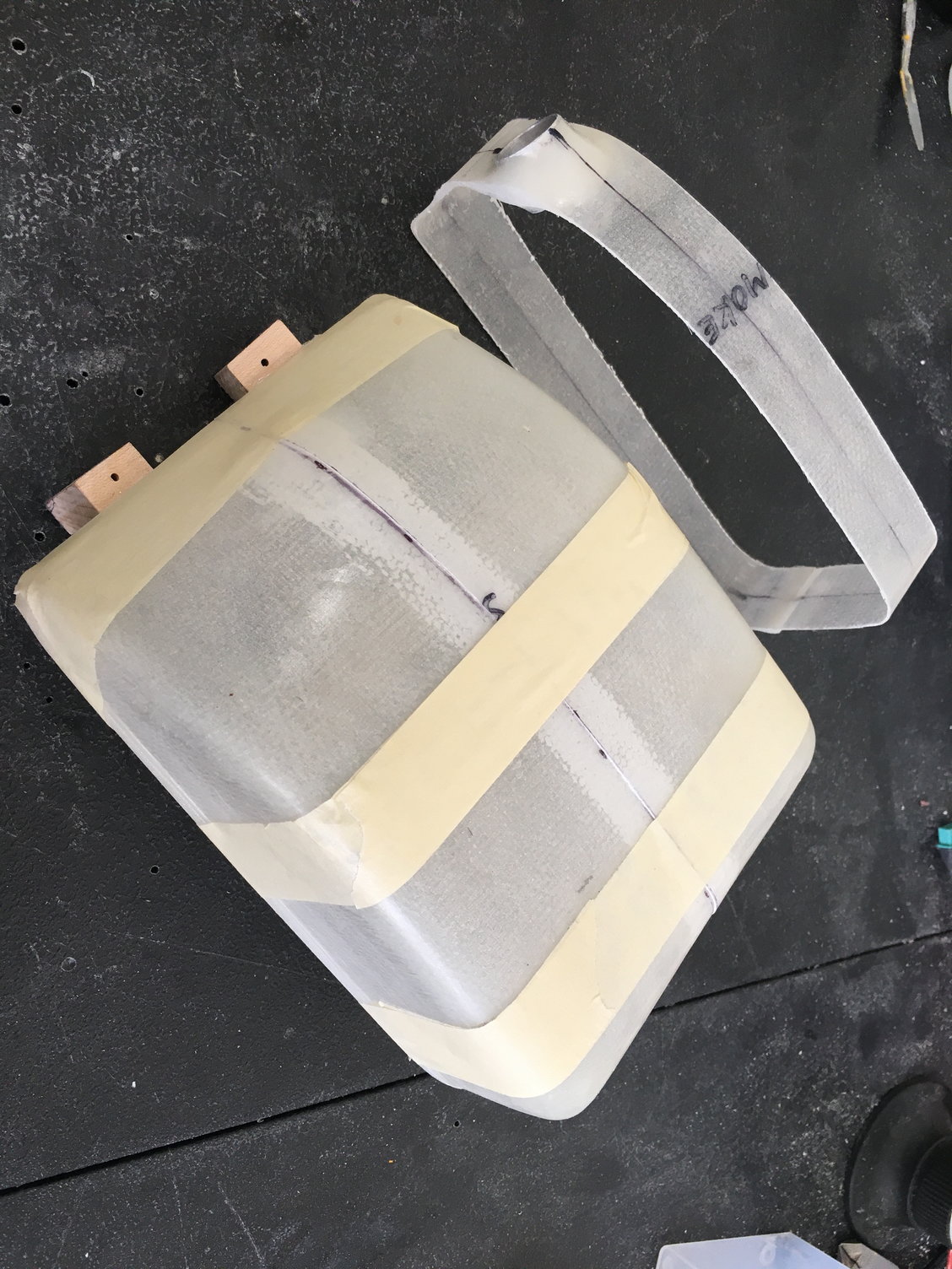
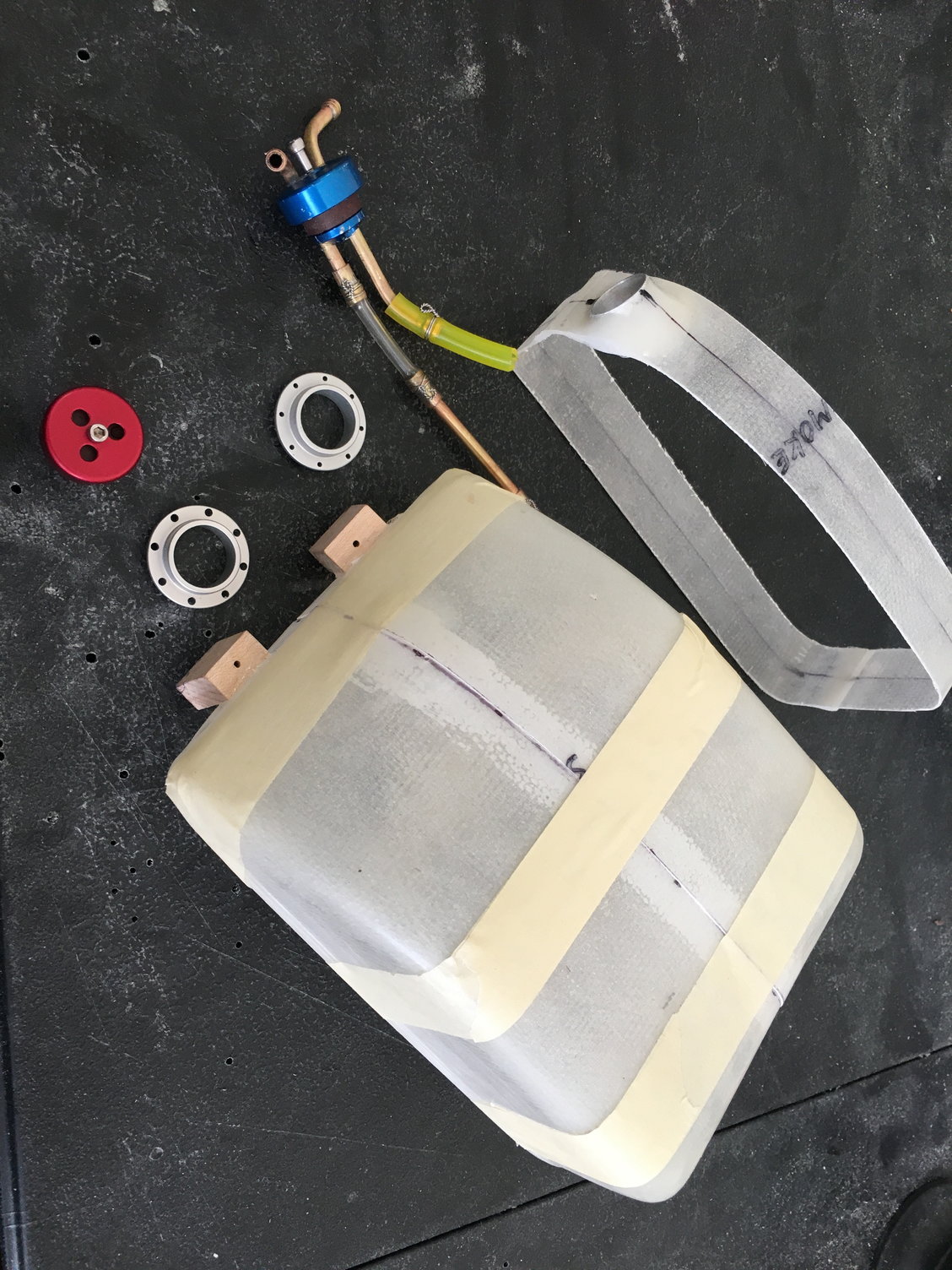
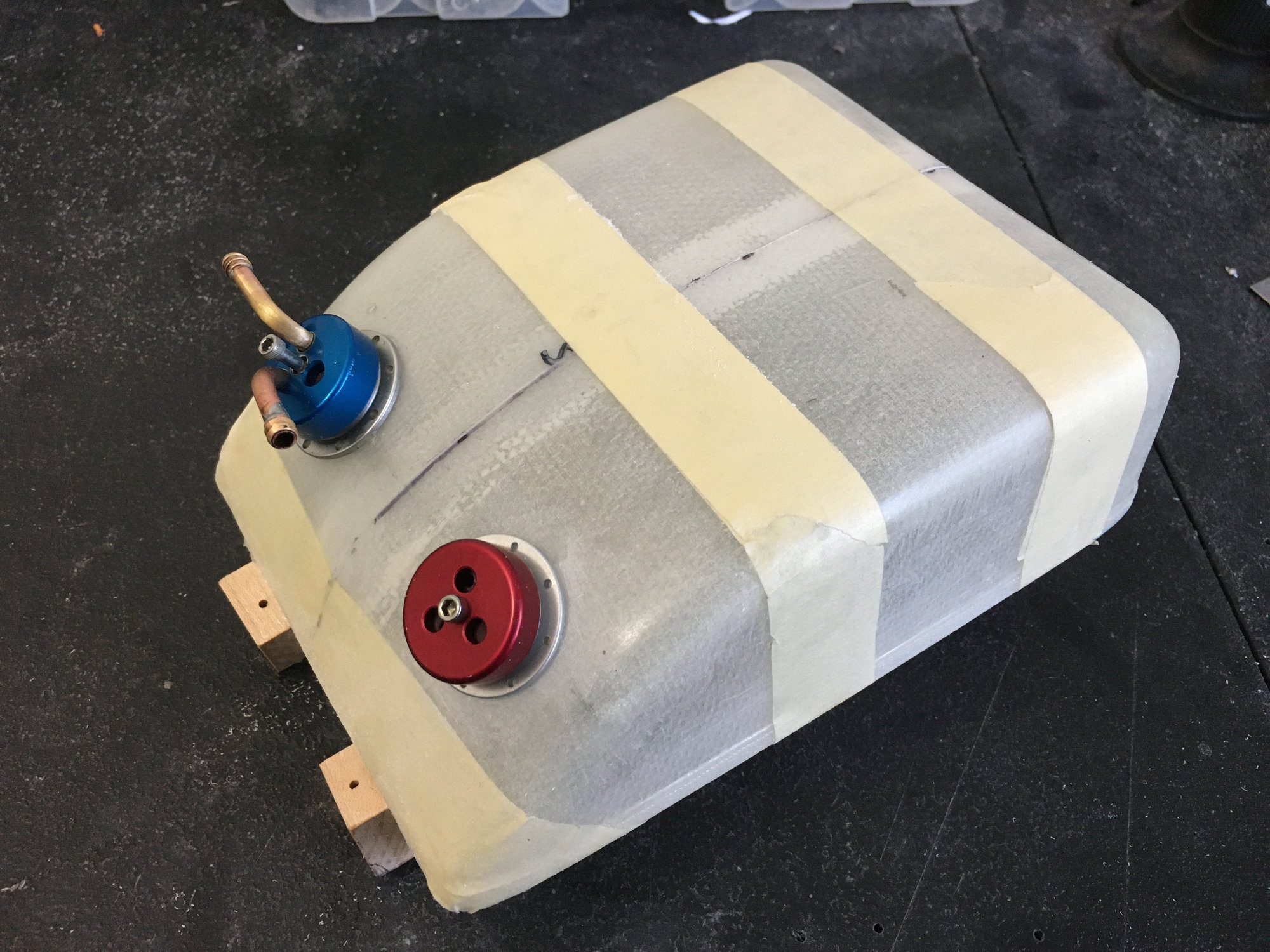
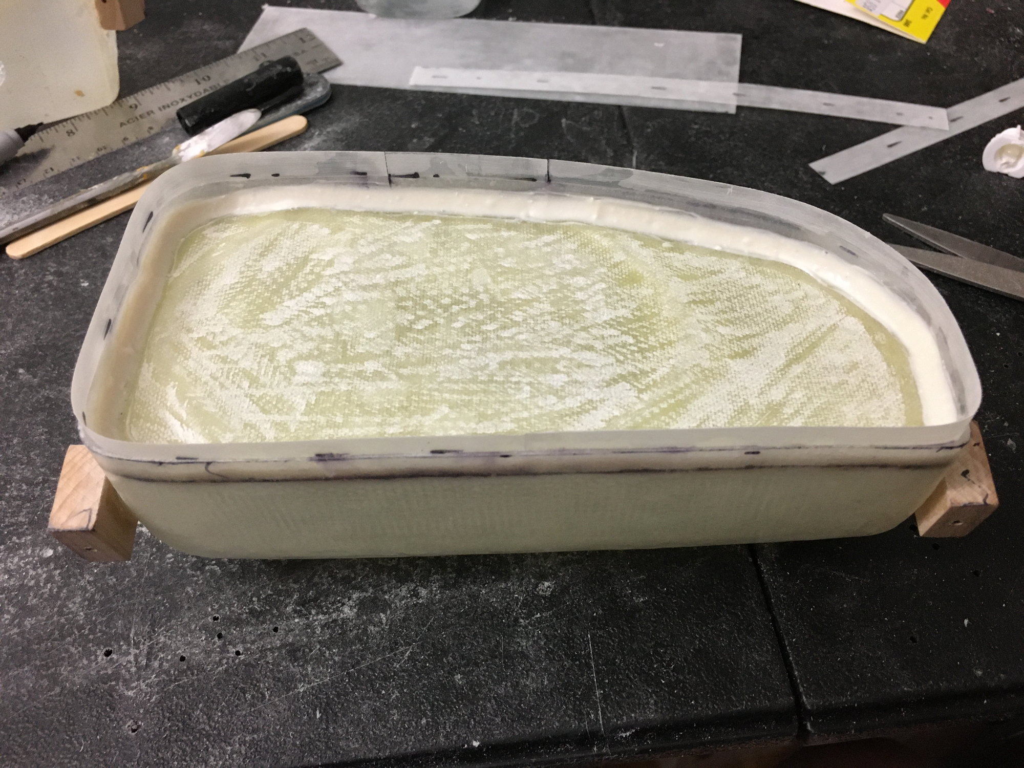
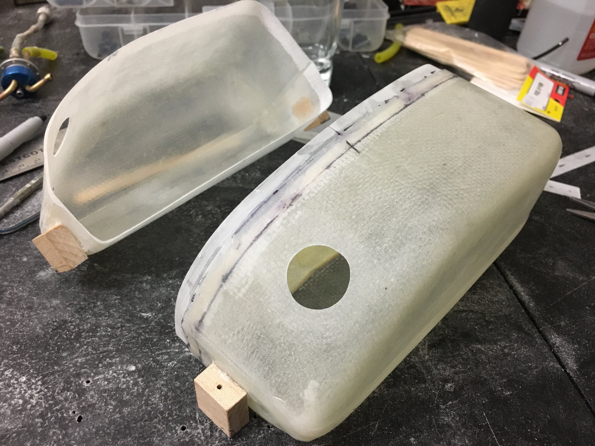
As you can see in the photos, I cut out the center portion of the tank (which contains the molded port for the fuel stopper). I drilled a hole in each side of the tank and Hysol'd the aluminum stopper adaptors (from Deamworks) to the tanks. I cut a .060" thick G-10 plate to separate the fuel from the smoke and Hysol'd it in place then Hysol'd a 1/2 wide x .010" thick strip of polyply to the inside of the tank (1/4" per side) to act as a guide when putting the tank back together.
After rejoining the tank halves, I glassed 3 wraps of 3/4" fiberglass tape over the seam. The tank has approx 20 oz of smoke and 20 oz of extra fuel which gives me a typical flight time (I mostly fly at 1/2 throttle) of about 11 minutes.
Regards,
Jim
As you can see in the photos above, the smoke tank partially obstructs the vents on either side of the belly. I also thought that using the stock setup gives you too much smoke and too little fuel. As such, I decided to convert the rear tank to a "combi" tank carrying both smoke and fuel. I also cut out about 3/4" of the width of the tank to make the tank narrower to allow the vents to breath better.
As you can see in the photos, I cut out the center portion of the tank (which contains the molded port for the fuel stopper). I drilled a hole in each side of the tank and Hysol'd the aluminum stopper adaptors (from Deamworks) to the tanks. I cut a .060" thick G-10 plate to separate the fuel from the smoke and Hysol'd it in place then Hysol'd a 1/2 wide x .010" thick strip of polyply to the inside of the tank (1/4" per side) to act as a guide when putting the tank back together.
After rejoining the tank halves, I glassed 3 wraps of 3/4" fiberglass tape over the seam. The tank has approx 20 oz of smoke and 20 oz of extra fuel which gives me a typical flight time (I mostly fly at 1/2 throttle) of about 11 minutes.
Regards,
Jim
Last edited by rcjets_63; 10-15-2022 at 04:17 PM.
The following users liked this post:
shrek514 (10-15-2022)
10-15-2022, 03:25 PM
#220
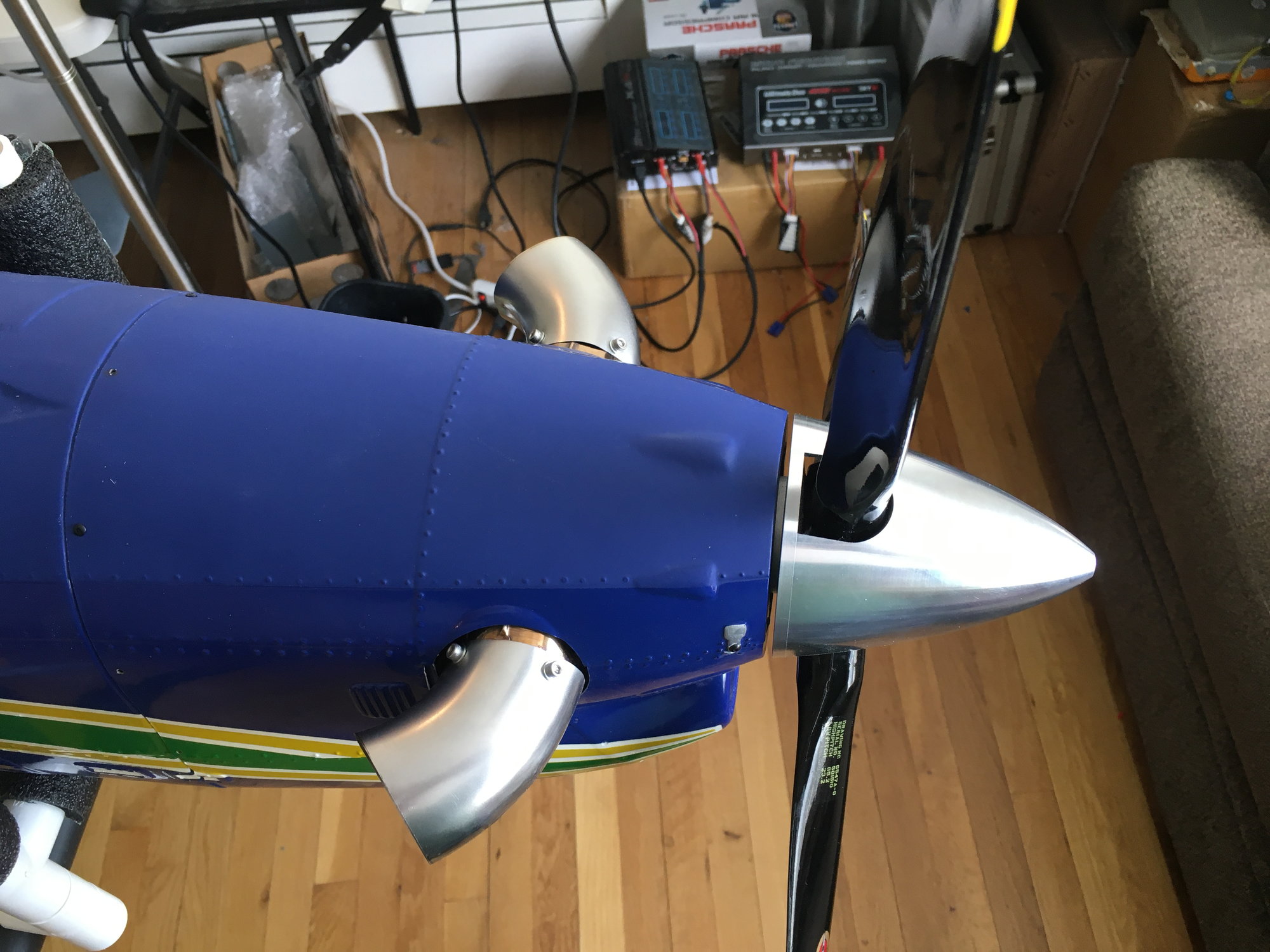
Exhaust Pipes
At the time of the build (end of 2019), there didn't seem to be a ready supply of 45-sized turboprop pipes. A friend and I experimented with making exhaust pipes from car exhausts and while they fit, they were way too heavy. Fortunately, I heard about Zimmerman in Germany and ordered a pair of pipes from them.
Here is a link to the pipes:
https://zimmermannschalldaempfer.de/...---k100tp.html
This is what I ordered:
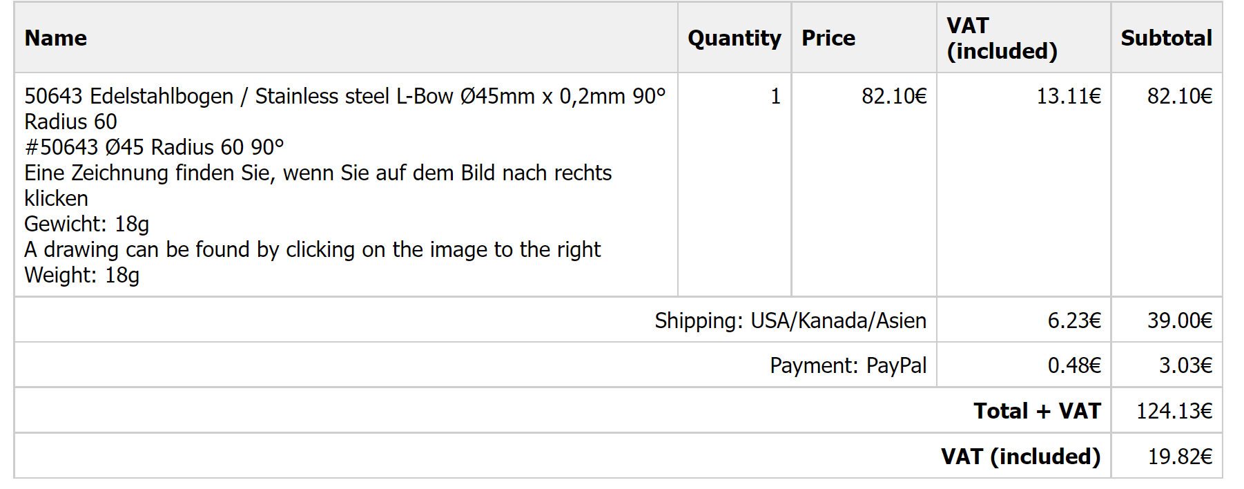
I seem to recall that these pieces are sold separately so I had to order two but quantity 1 is shown on the bill (I don't speak German but maybe the German word for "pair" is somewhere on the bill, lol). Notice the part number of #50643 on the invoice. As far as I can tell, these pipes seem to have the current part number of #50602. The pipes have a diameter of 45mm, are 90-degree elbows, and have a inside bend radius of 60mm. The pipes fit beautifully onto the K-45 TP engine.
Two items about the pipes, you have to cut off the end (approx 50-degrees) to a scale shape (I found a nice top view of the full scale on the internet) which was simple enough with a Dremel and a cutoff wheel. You also have to drill through holes for the mounting bolts which thread into the exhaust duct of the K45TP. It was simple enough to mark the radial location of the threaded holes, put the pipes in place. draw a line around the edge of each pipe, measure the distance from the line to the center of each hole and drill clearance holes for the bolts.
BTW, if any of you have experienced difficulty drilling holes through thin wall stainless steel, here is a trick that I learned. DO NOT ATTEMPT TO DRILL AT HIGH SPEED. A variable speed electric handheld drill is best. Put a ~1" dowel in a vice and use it to support the inside of the pipe, then using a fair amount of pressure and very little RPM (maybe 1 rev/sec), engage the drill. After a few turns the drill will cut through the pipe, no problem. A few more revs clears away the cut chip from the pipe. Insert the bolts, and you're done.
Regards,
Jim
At the time of the build (end of 2019), there didn't seem to be a ready supply of 45-sized turboprop pipes. A friend and I experimented with making exhaust pipes from car exhausts and while they fit, they were way too heavy. Fortunately, I heard about Zimmerman in Germany and ordered a pair of pipes from them.
Here is a link to the pipes:
https://zimmermannschalldaempfer.de/...---k100tp.html
This is what I ordered:
I seem to recall that these pieces are sold separately so I had to order two but quantity 1 is shown on the bill (I don't speak German but maybe the German word for "pair" is somewhere on the bill, lol). Notice the part number of #50643 on the invoice. As far as I can tell, these pipes seem to have the current part number of #50602. The pipes have a diameter of 45mm, are 90-degree elbows, and have a inside bend radius of 60mm. The pipes fit beautifully onto the K-45 TP engine.
Two items about the pipes, you have to cut off the end (approx 50-degrees) to a scale shape (I found a nice top view of the full scale on the internet) which was simple enough with a Dremel and a cutoff wheel. You also have to drill through holes for the mounting bolts which thread into the exhaust duct of the K45TP. It was simple enough to mark the radial location of the threaded holes, put the pipes in place. draw a line around the edge of each pipe, measure the distance from the line to the center of each hole and drill clearance holes for the bolts.
BTW, if any of you have experienced difficulty drilling holes through thin wall stainless steel, here is a trick that I learned. DO NOT ATTEMPT TO DRILL AT HIGH SPEED. A variable speed electric handheld drill is best. Put a ~1" dowel in a vice and use it to support the inside of the pipe, then using a fair amount of pressure and very little RPM (maybe 1 rev/sec), engage the drill. After a few turns the drill will cut through the pipe, no problem. A few more revs clears away the cut chip from the pipe. Insert the bolts, and you're done.
Regards,
Jim
Last edited by rcjets_63; 10-15-2022 at 03:27 PM.
The following users liked this post:
shrek514 (10-15-2022)
10-15-2022, 03:34 PM
#221
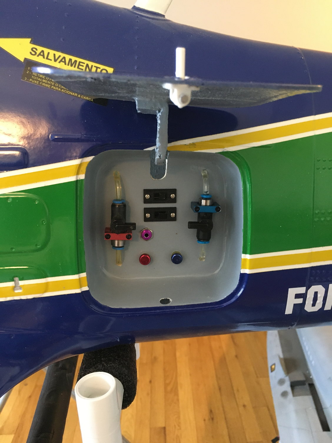
Hatch Area
I did a layout of the hatch are for locating switches (Rx - upper, lights - lower), fuel and smoke fill Tygon tubing, and fuel and smoke 1/4 turn valves (red for fuel, blue for smoke), and a BVM fill valve for the pneumatics. I glued a 1/8 lite ply back plate to the back of the recess. Has worked great for years.
Regards,
Jim
Last edited by rcjets_63; 10-15-2022 at 04:35 PM.
The following users liked this post:
shrek514 (10-15-2022)
10-15-2022, 04:34 PM
#223
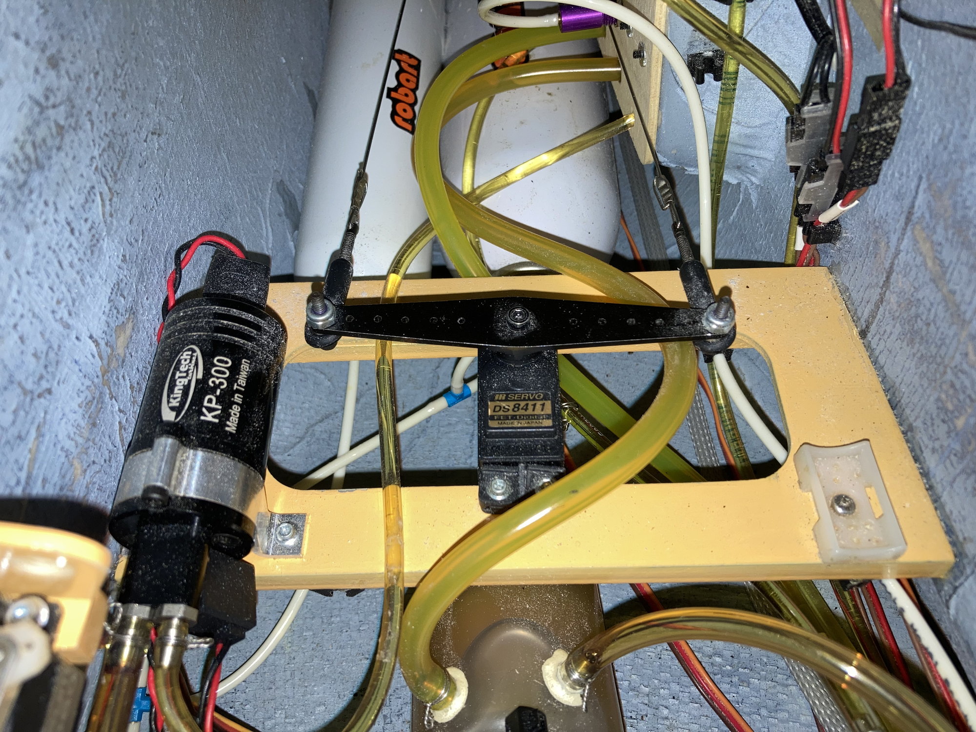
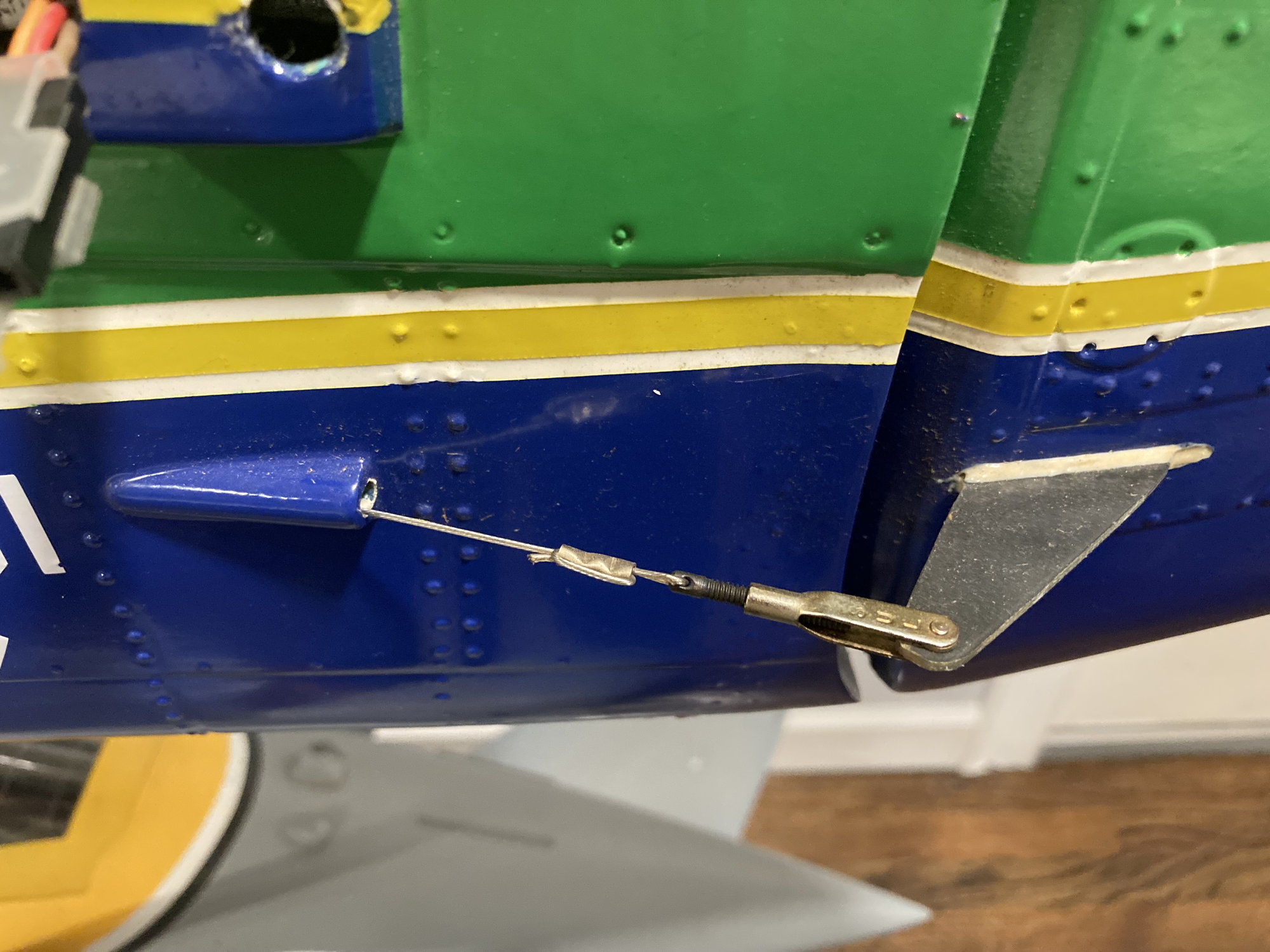
Rudder servo, Fuel Pump, Smoke Pump
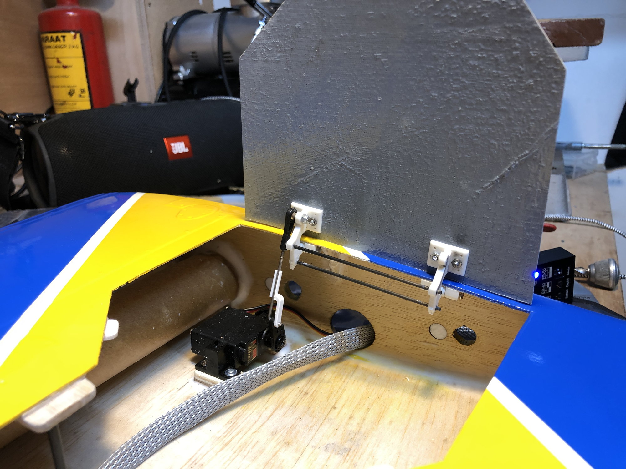
It was pretty tricky to fit this all onto one shelf near the back of the cockpit cutout. The output arm for the rudder servo is 3-1/2" between outer drive holes, and this left just enough space for the Kingtech fuel pump and BVM smoke pump to be mounted and just clear. The size of the output arm was based on the control horn for the rudder. Maybe a 3D guy would know what's available out there but I had no idea so I made the rudder arms from a .060" thick CF plate. I made a 1-1/2" long slot completely through the rudder, pushed a 1-1/2 wide strip of CF plate through the slot, then made a couple of lines on the plate to mark the cross section of the rudder in this area. Then I draw a control arm shape onto the strip at each end of the center section. The holes were about 3-1/2 inches apart so I needed a similar double ended servo arm so that the pull-pull cables didn't tighten/slack when the rudder is deflected.
The Kingtech pump was screwed to one end of the plate in the fuselage and a plastic cradle mount on the other end. Sorry, but in the photo the BVM smoke pump isn't shown (as I recently borrowed it to put it in another plane) but you guys are all bright enough to imagine it in place.
Regards,
Jim
Last edited by rcjets_63; 10-15-2022 at 04:38 PM.
The following users liked this post:
shrek514 (10-15-2022)
10-15-2022, 05:30 PM
#224
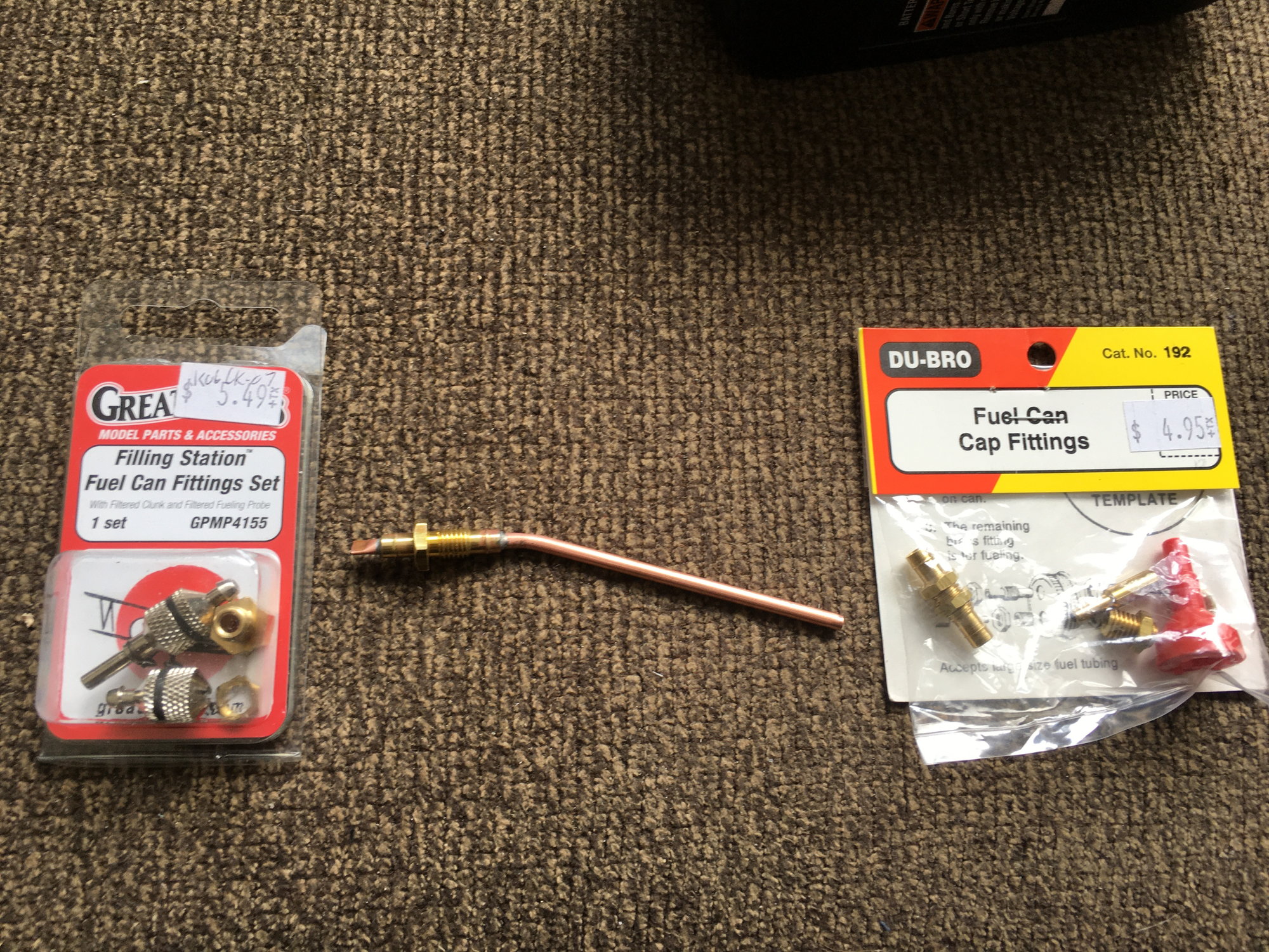
Smoke Nozzle
At the time (I'm not sure what is available now) there were no exhaust pipes or smoke nozzles available for the K45TP. The exhaust pipes were discussed a few posts ago but here is what was done for the smoke injection nozzle...
I called Barry at Kingtech and asked permission to drill a hole in the exhaust manifold (without voiding the turbine warranty). He agreed, but asked me to be careful and to stuff a paper towel into the manifold to catch any metal chips and not let them fall inside the turbine or gearbox. Sure, no problem.
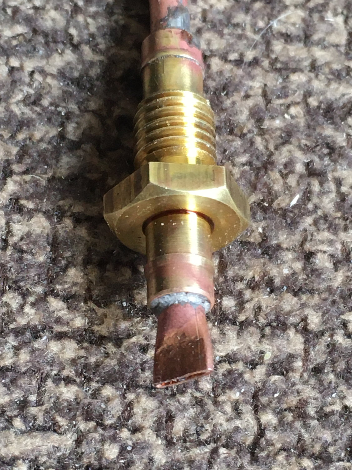
I bought a length of 1/8" copper tubing from K&S and cut a strip of .005" thick stainless steel shim stock to approx 3/16" wide then used a bench vise to crimp the end of the tubing. When the tubing was almost flat, I inserted the .005" strip about 1/4" into the partially crimped tubing then cranked the vice closed. After removing the crimped tubing from the vice, I pulled out the .005" stainless steel strip to leave a nice .005" gap in the nozzle.
To make the nozzle mount, I used parts from a fuel can cap fitting set (see photo for P/N's).
I inserted the tubing into the fuel can fitting and silver soldered it to the fitting) as needed to position the copper tubing where I figured the stream of smoke fluid would be centered in the exhaust port.
I actually drilled two holes in the manifold (for a nozzle on each side). Rogerio Araujo, a Top Gun buddy who hails from Brazil), busted me on this. Apparently, the Brazilian team (the "Smoke Squadron") only uses smoke only on one side (I can't remember if it is the left or the right but you can look for pics for the full scale) so I should have only drilled a hole for one nozzle.
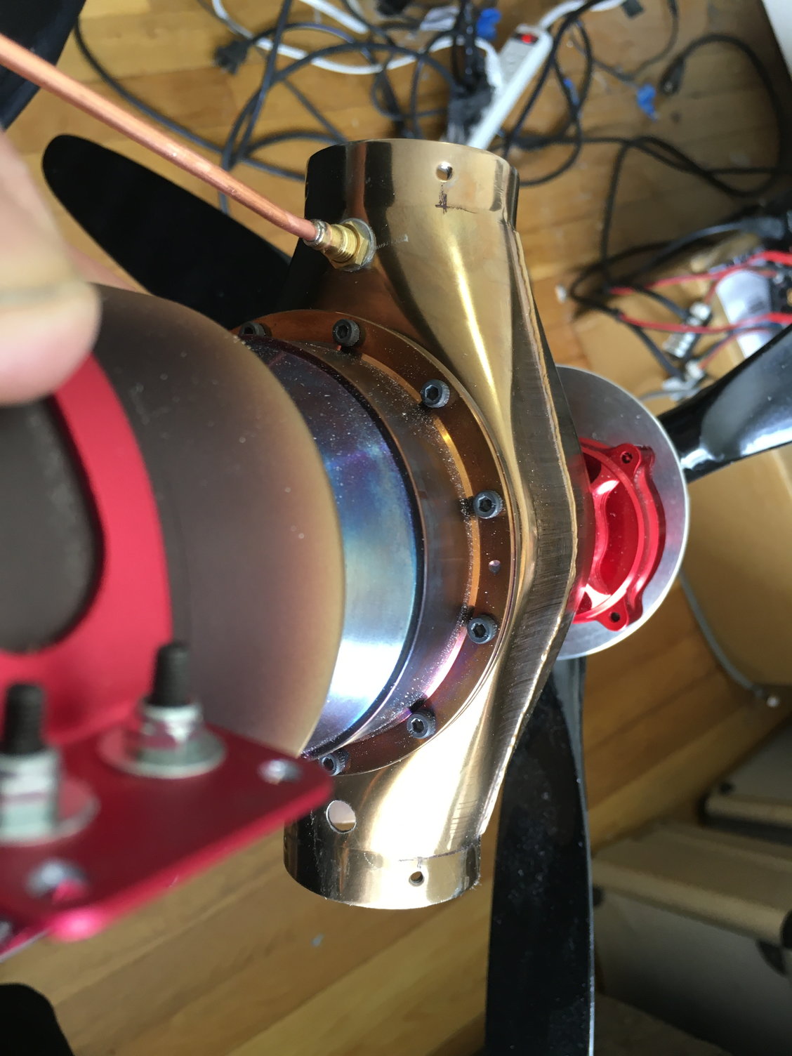
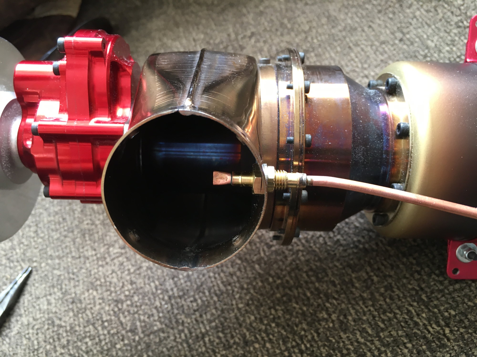
I forced a piece of 4mm teflon tubing (available from McMaster Carr) over the end of the copper tubing, safety wired it to the tubing, then used a 4mm Festo union to connect it to the regular 4mm tubing we use for fuel or smoke lines. Here's a pic of my final installation:
Regards,
Jim
At the time (I'm not sure what is available now) there were no exhaust pipes or smoke nozzles available for the K45TP. The exhaust pipes were discussed a few posts ago but here is what was done for the smoke injection nozzle...
I called Barry at Kingtech and asked permission to drill a hole in the exhaust manifold (without voiding the turbine warranty). He agreed, but asked me to be careful and to stuff a paper towel into the manifold to catch any metal chips and not let them fall inside the turbine or gearbox. Sure, no problem.
I bought a length of 1/8" copper tubing from K&S and cut a strip of .005" thick stainless steel shim stock to approx 3/16" wide then used a bench vise to crimp the end of the tubing. When the tubing was almost flat, I inserted the .005" strip about 1/4" into the partially crimped tubing then cranked the vice closed. After removing the crimped tubing from the vice, I pulled out the .005" stainless steel strip to leave a nice .005" gap in the nozzle.
To make the nozzle mount, I used parts from a fuel can cap fitting set (see photo for P/N's).
I inserted the tubing into the fuel can fitting and silver soldered it to the fitting) as needed to position the copper tubing where I figured the stream of smoke fluid would be centered in the exhaust port.
I actually drilled two holes in the manifold (for a nozzle on each side). Rogerio Araujo, a Top Gun buddy who hails from Brazil), busted me on this. Apparently, the Brazilian team (the "Smoke Squadron") only uses smoke only on one side (I can't remember if it is the left or the right but you can look for pics for the full scale) so I should have only drilled a hole for one nozzle.
I forced a piece of 4mm teflon tubing (available from McMaster Carr) over the end of the copper tubing, safety wired it to the tubing, then used a 4mm Festo union to connect it to the regular 4mm tubing we use for fuel or smoke lines. Here's a pic of my final installation:
Regards,
Jim
Last edited by rcjets_63; 10-15-2022 at 05:44 PM.
The following users liked this post:
shrek514 (10-15-2022)
10-15-2022, 05:54 PM
#225
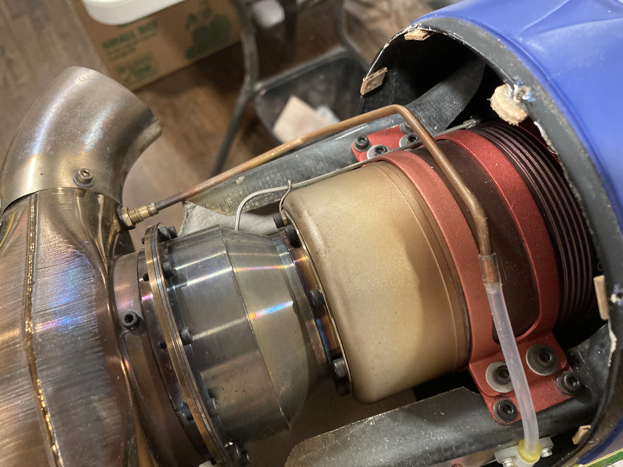
Gearbox Lubrication Tube
Kingtech runs a piece of stainless steel tubing from the connector near the engine fuel fitting to the gearbox to provide lubrication to the gearbox. Unfortunately, there isn't enough room under the cowl to allow the use of the stock tubing. As an alternative, I used a piece of teflon tubing to make the connection. I drilled a hole in the underside of the engine mount, and then ran the tubing to the engine, through the hole, and out to the connection at the side of the gearbox. Easy peasy, no issues here.
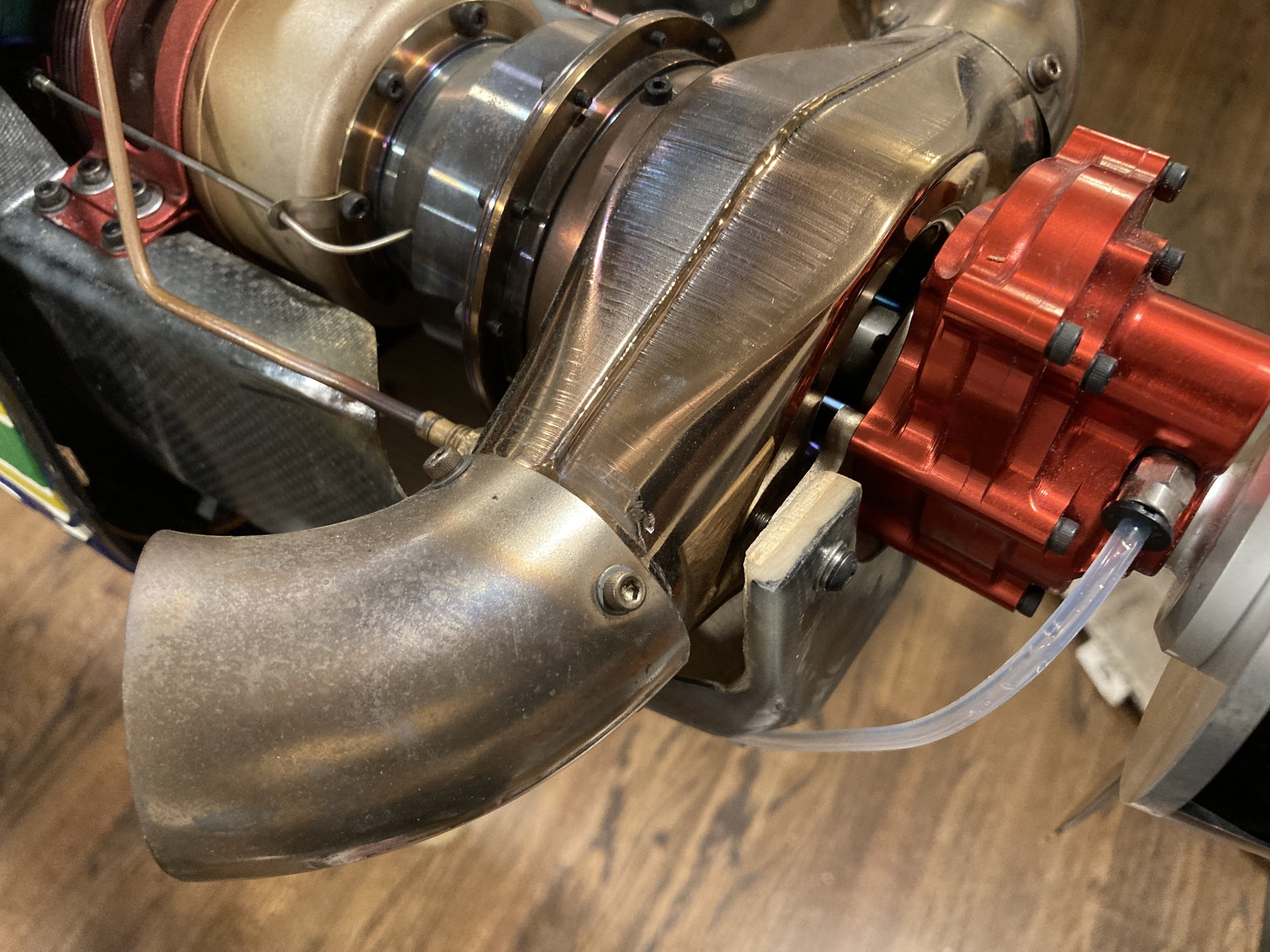
Note: I pulled the screws out of the nose wheel mount when landing on a soggy grass field earlier this year. Fortunately, I didn't even break the prop but repairing the wood mount took some care.
Regards,
Jim
Kingtech runs a piece of stainless steel tubing from the connector near the engine fuel fitting to the gearbox to provide lubrication to the gearbox. Unfortunately, there isn't enough room under the cowl to allow the use of the stock tubing. As an alternative, I used a piece of teflon tubing to make the connection. I drilled a hole in the underside of the engine mount, and then ran the tubing to the engine, through the hole, and out to the connection at the side of the gearbox. Easy peasy, no issues here.
Note: I pulled the screws out of the nose wheel mount when landing on a soggy grass field earlier this year. Fortunately, I didn't even break the prop but repairing the wood mount took some care.
Regards,
Jim
The following users liked this post:
shrek514 (10-15-2022)