


Skymaster F-14 Jolly Roger
 10-19-2021, 06:43 AM
#76
Congrats on your Tomcat!! I'm in the process of changing some things on mine, and most issues I read are familiar.
- Gear: I stripped all the factory paint on mine, took everything apart (the gear is indeed a work of art!), painted all parts individually, and reassembled it all with proper lubing. Originally on mine, there was a lot of drag on the sleeve that connects to the scissor (main gear), due to a very viscous oil or grease. same on the steering sleeve on the nose gear. goes a lot smoother now. Do indeed take care to not slam the gear down, I ripped the rod right out of the piston on the locking cylinder. also, when adjusting the locking cylinder, don't let the scissor go too far over center, the small piston just isn't strong enough. I use 10 bar on mine, and two of the largest cylinders I could find. these are mounted in between the turbines and used for gear and doors. Two large Robart cylinders power the rest. I use Evojet valves with throttles on the exhaust.
- doors: I optimized piston throw on the main wheel doors. modified the hinge to have a longer arm to match the piston throw. moves a lot smoother now.
- cockpit: the original is junk indeed. Shame on SM to even charge for this! In the process of making a new cockpit. (.6mm ply)
- Flap travel: correct placement of the actuator rod is indeed essential. the bend in the rod needs to be in perfect alignment with the hinge line. max deflection is actually the same as the bend in the rod (about 45� I think).
Check the slot in the flap in which the rod rides. if play occurs there, you will need to open the flap and add plates (Fiberglass or carbon). Or go to an external linkage.
- Rudder: I am planning to optimize the geometry of the linkage. did mine as per manual, but not entirely satisfied. also, there's play in the hinge. hinge wire is a hair too thin.
- thrust tubes: you can adjust the front to back placement with the two M3 threaded rods. back of my pipes are about flush with the back of the nozzles.
- Fuel system: mine is as stated in the manual, no issues. Split front tank does seem a nice addition, I do have concerns of the clunks getting tangled together..... single fueling point, single vent.
- important: check the wing incidence after taking out the wing swing mechanism!!! a small misalignment on the main beam (the one that bolts between the two formers, and to which the pivots attach) can have a large impact on the wings. ask me how I know.... :-) easily checked by swinging the wings back, and measure the distance between the wingtip and your tabletop with the fuse levelled.
mine came out at 28kg's empty (no lead!), hoping to shave some weight off by moving stuff around (shorter and lighter -Powerbox- cabling)
Flies like a trainer with the wings out.......a fast, heavy trainer. :-)

The following users liked this post:
gpman (10-24-2021)
 10-23-2021, 01:31 AM
#78

Im not understanding their response, the front of the pipe has to be supported some how. All pipes are supported in the rear and front, anyway I can try but that's really hard to do without taking the rear apart a bit. Do you know id the pipes are short or is it the mounts being too short? The only way to push the pipes back far enough and keep your turbine to pipe gap is push the motors back. Its go to almost impossible to get the motors in the far back inside the model.
I also don't trust this setup and added the nuts even if it's a pain to get to them, especially with the bigger engines.
10-23-2021, 10:21 AM
#79

Speaking with Likai about this issue some time ago, he was telling me the front of the pipe has been designed to just 'stick' in the engine rails, without the nuts. The pipe is then retained at the back by that little metal tab which is spot welded and is trapped by the exhaust cone.
I also don't trust this setup and added the nuts even if it's a pain to get to them, especially with the bigger engines.
I also don't trust this setup and added the nuts even if it's a pain to get to them, especially with the bigger engines.
 11-16-2021, 10:42 AM
#80
Thread Starter
Thanks WimB, Ravill and Keith, most of the issues already sorted out. As for the tail pipes, John (SM) sent me some pictures of a new kit they are about to complete.
Tail pipe is 22", and while mounted to the engine rail, it is flush with the tail cone as it should. Might be that in my kit the engine rails are too short, I can't see any other reason.
I added a 2.5" (4 cm) extension to the tail pipes at the end, not sure it's the right way. Might be that I had to extend it after the bell mouth. Don't know....
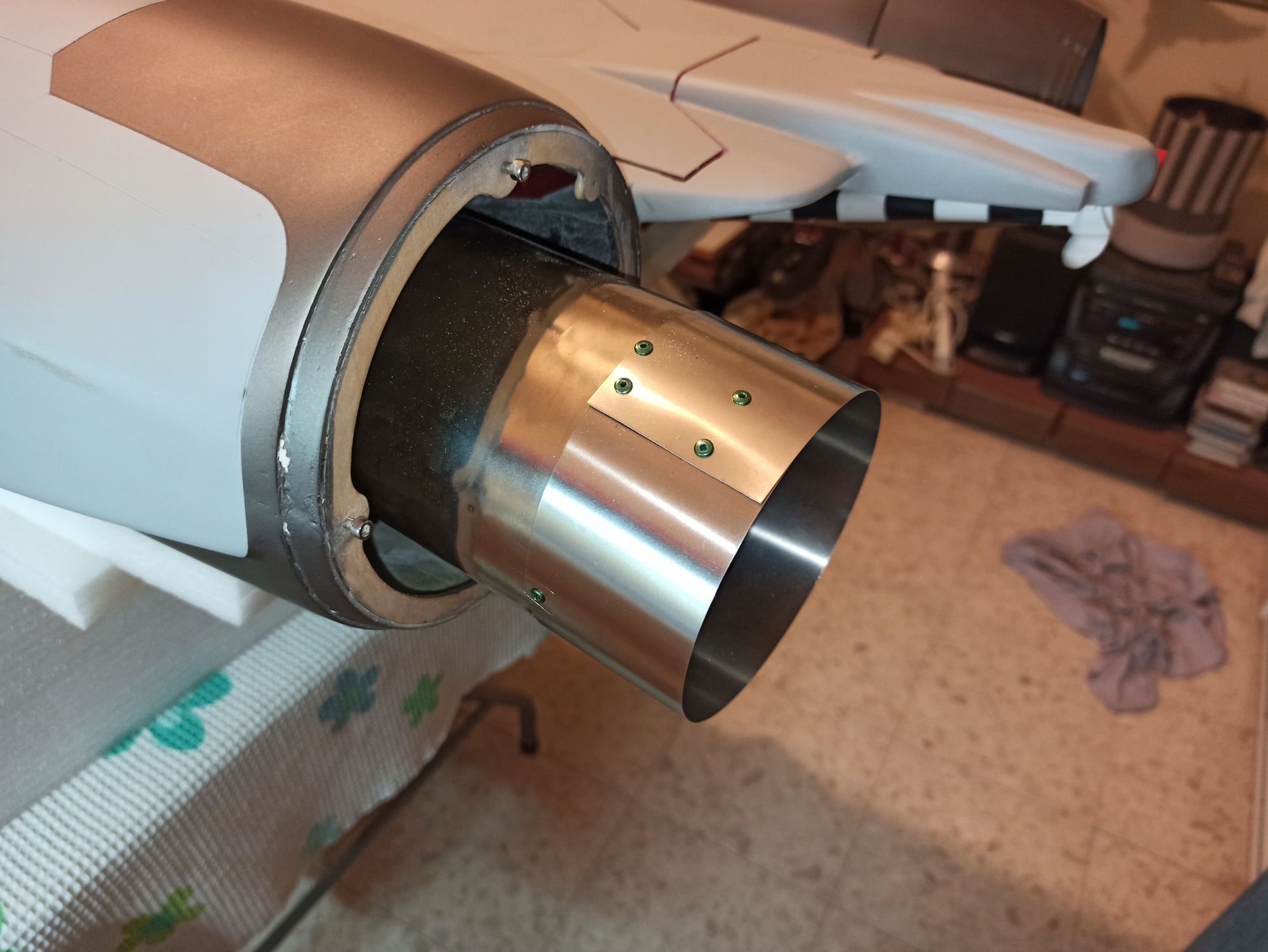
Adding stainless steel 0.3mm strip
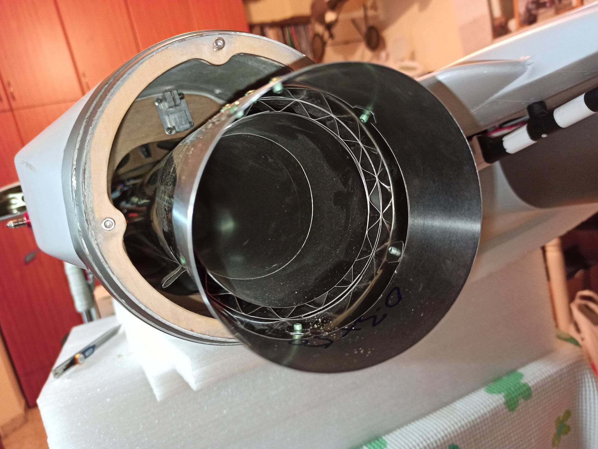
inside view
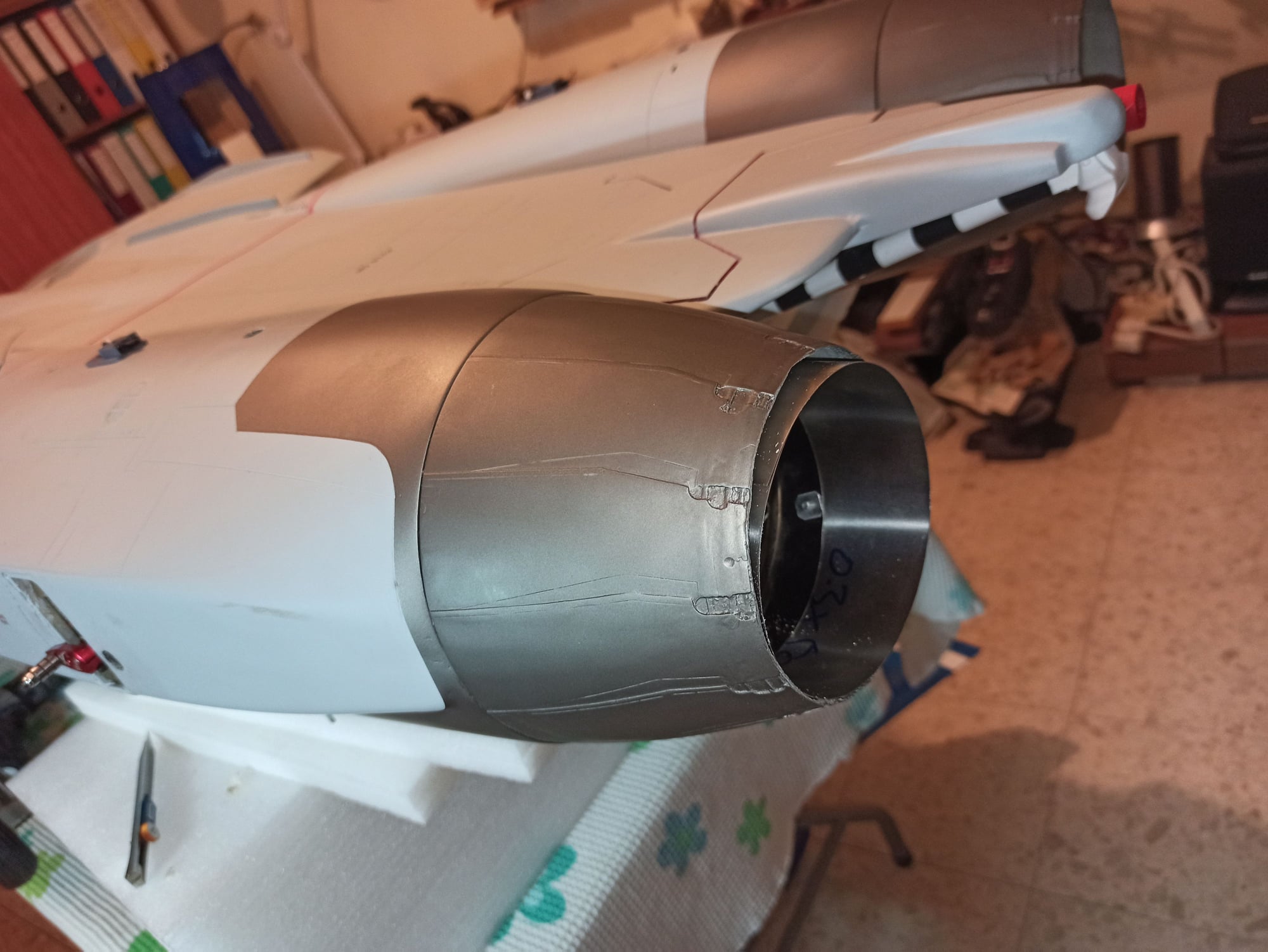
Need a little trim and it's done
Tail pipe is 22", and while mounted to the engine rail, it is flush with the tail cone as it should. Might be that in my kit the engine rails are too short, I can't see any other reason.
I added a 2.5" (4 cm) extension to the tail pipes at the end, not sure it's the right way. Might be that I had to extend it after the bell mouth. Don't know....
Adding stainless steel 0.3mm strip
inside view
Need a little trim and it's done
 11-24-2021, 01:18 PM
#82
Here�s a quick vid of my 4th flight....still working on getting her dialed in with wing sweep...
https://youtu.be/p-UIYTRgZ38
https://youtu.be/p-UIYTRgZ38
Hi,
Are you using Lipo 7.4V to power the Wing actuators?
Tks
Bruno
 11-25-2021, 11:57 AM
#84
11-25-2021, 12:01 PM
#85
That makes sense actually as my actuators are non proportional and don�t have any intermediate settings�.I got my kit new off a fellow that had it for a while so it was manufactured probably in 2016 or 17
11-25-2021, 10:20 PM
#87
Yeah my controller burned up at KY jets this year, I replaced mine with the version mentioned above. Looking forward to trying them since I can set a mid sweep position like the real one flew at instead of just full back/full out.
11-26-2021, 04:50 AM
#88
That's cool....I may get the newer controller as well...my buddy's has it and it's nice having the mid position

 11-27-2021, 07:22 PM
#90
Honestly, I have no clue�.I know the full scale had an auto mode where they would start to sweep at a certain speed (Mach number)�..there�s was also a manual mode the pilot could select�.Beyond that perhaps someone else can chime in to answer your question..

The following users liked this post:
camss69 (11-28-2021)
The following users liked this post:
Dansy (11-29-2021)
11-29-2021, 05:20 AM
#93
11-29-2021, 06:28 AM
#94
11-30-2021, 04:49 PM
#95

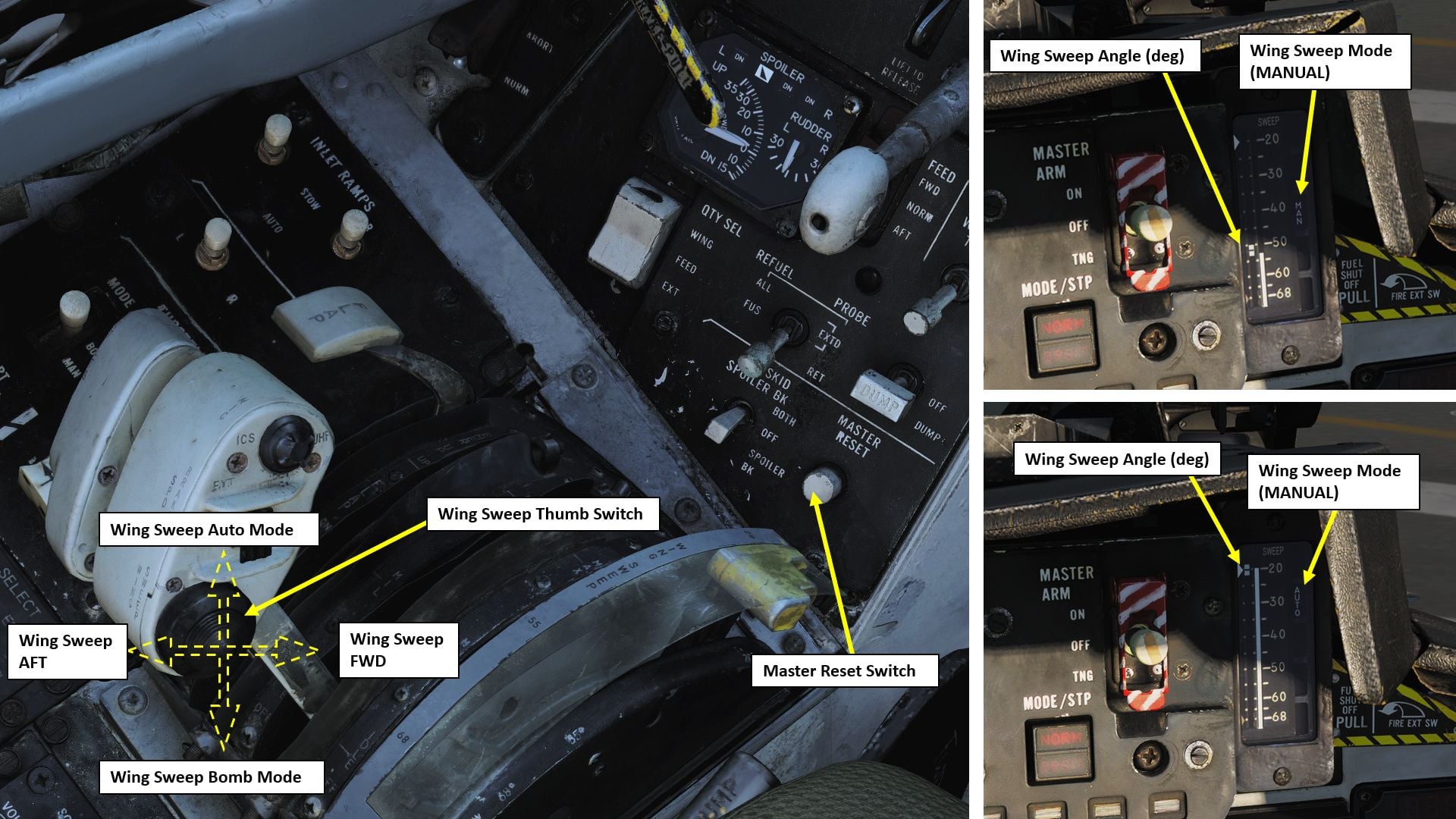
The wings could be over swept back, not for flying, so the plane was slightly smaller for storage on the carrier, 75deg sweep angle. Basically 4 manual positions and Auto plus Emergency for fine angle control. FWD/Bomb/Back/Oversweep
From NATOPS see page 2-82
https://info.publicintelligence.net/F14AAD-1.pdf
Image of the DCS F-14 simulator shows the controls and the gauge.
Last edited by Chris Nicastro; 11-30-2021 at 05:12 PM.
11-30-2021, 11:24 PM
#96
Thank you all .. great information..
I believe the new SM F14 wing mechanisms (@7.4V) has three position.. each wing position will have a respective flight mode with corresponding ailevator travel and gyro gains. I will name the modes as � Forward�, �Attack� and �Stealth�
As for power plant.. I anticipate twin matching Xicoy �X180��
David
The following users liked this post:
Canadian Man (01-10-2022)
12-01-2021, 10:50 AM
#97
Beautiful scheme.....
If I'm not mistaken from helping my buddy do some programming on his, they're basically like a servo...So you can chose what intermediate position(s) you would want within the radio programming...Don't quote me on this but I think that's how they work
If I'm not mistaken from helping my buddy do some programming on his, they're basically like a servo...So you can chose what intermediate position(s) you would want within the radio programming...Don't quote me on this but I think that's how they work
05-25-2022, 02:51 AM
#99
My buddy had around 200 flights on his before he sold it….with the basic wing, it flew fantastic and he loved the jet….I myself have the fancy one as the cool factor was too much to turn away 🙂…I’m going to be really dialling mine in this year…Hoping to get a lot more flights on mine as well
The following users liked this post:
mugenkidd (05-25-2022)
05-25-2022, 04:11 AM
#100

There were no "detent" positions for the wing sweep. It had either an automatic or manual mode: In automatic mode, the flight computer determined the wing position based on altitude and speed (possibly weight as well). In manual mode, the pilot could put the wings anywhere they wanted, but the computer would not allow the wings to be un-swept beyond the position that the computer would allow in automatic mode, this was to prevent any structural damage from happening. Once they started using the F14 for bombing, they would manually put the wings at 55* of sweep for bomb runs