


Regal Eagle Recycled
 09-05-2020 | 10:56 AM
#26
Thread Starter

My Feedback: (13)
Okay,
I took a few days and glassed the inside of the rear airframe both for fuel proofing and because I am afraid of overpressure inside the fuse at higher speeds.
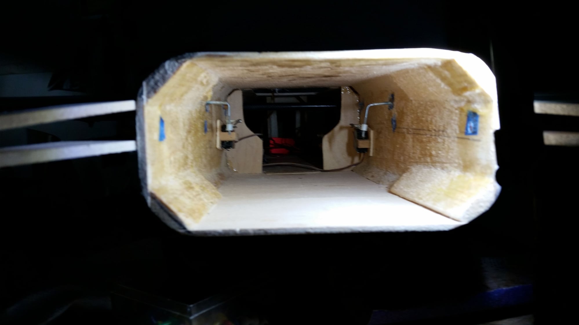
Here I have one vertical retract mount Hysoled in place.
I installed one retract to check the clearances before doing the second.
I tilted and cambered the mounts to retract into the fuse entirely instead of making bubbles on the sides to accept them. This will make sanding the sides much easier. This is also the maximum spread I can give the main wheels and keep them from tilting.
Just visible forward of the retracted gear is the marked position of the front fuse section. I had intended going with a 50oz tank but it won't fit and allow the gear to retract. I ordered a 40oz tank but that may not fit either. I will try a 32oz one as soon as I get a chance. A 24oz tank will fit , so if necessary I will use a couple of tanks in series.
Next I will probably fit the front section but may go back and fit the wings next. Those are a "chicken and egg" situation as the wings have to be in place for the torque rods to go in the holes I provided, and simultaneously slip onto 5" of carbon rod on each side. I'm still pondering that. I think I may have a solution short of cutting off the torque rods.
The retracts are JP. The struts are Robart struts with about a 15deg angle on the axle. As far as I can tell no longer available, or at least not listed on their site. The brakes are Xicoy with 5mm threaded axels. It turns out the solution of the mix between SAE and metric was more simple than I thought. It is possible to tap the 3/16" axle hole in the Robart strut with a 5mm tap which then takes the threaded axle well. Those are installed with Loctite blue. The brakes are installed with a little JB weld behind the brake backplate to make up for the disparity between the backplate anti rotation lugs and the sides of the axle hub. I seems pretty solid.
John
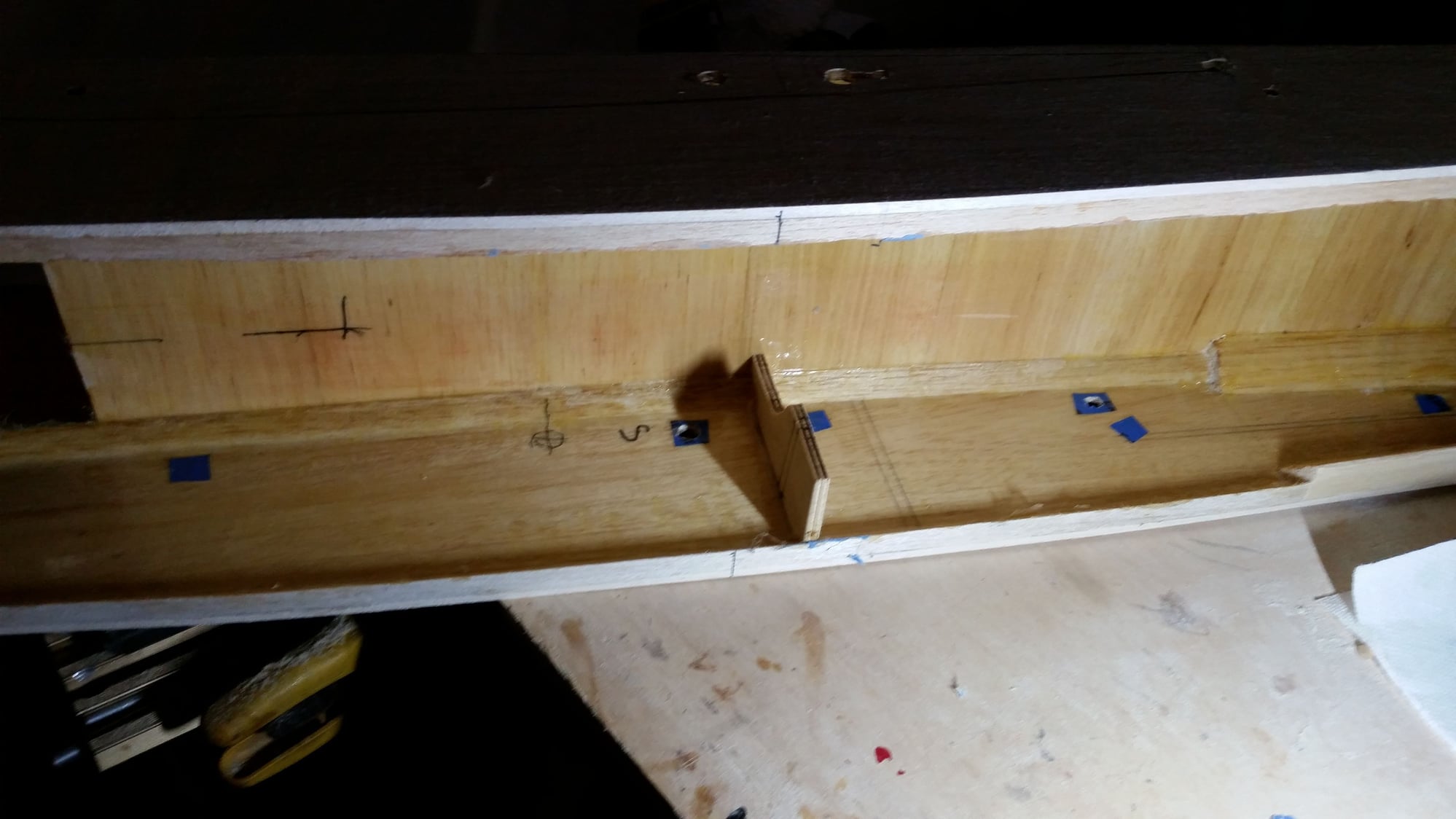
I took a few days and glassed the inside of the rear airframe both for fuel proofing and because I am afraid of overpressure inside the fuse at higher speeds.
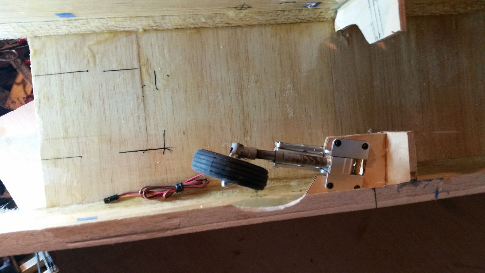
Here I have one vertical retract mount Hysoled in place.
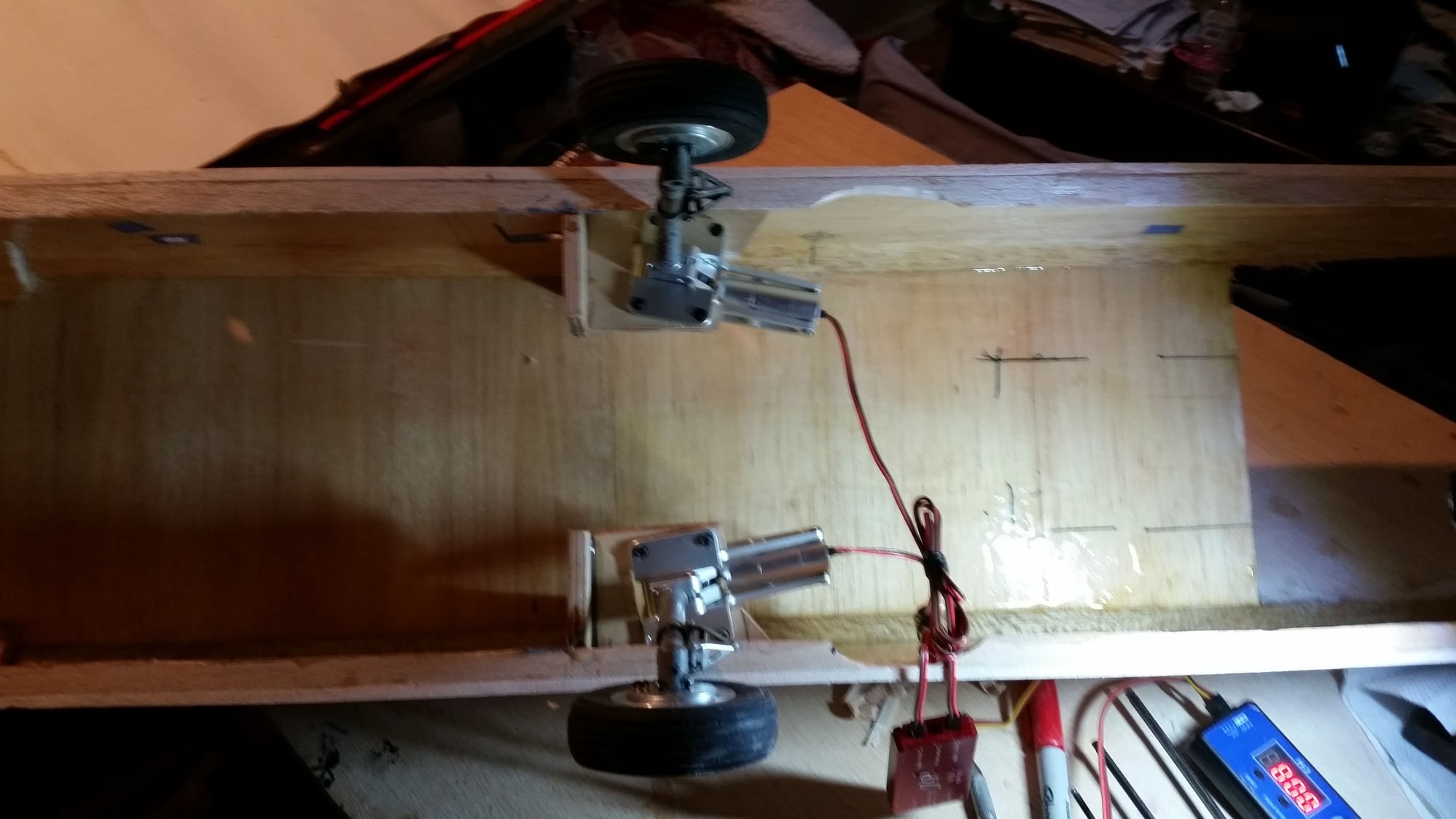
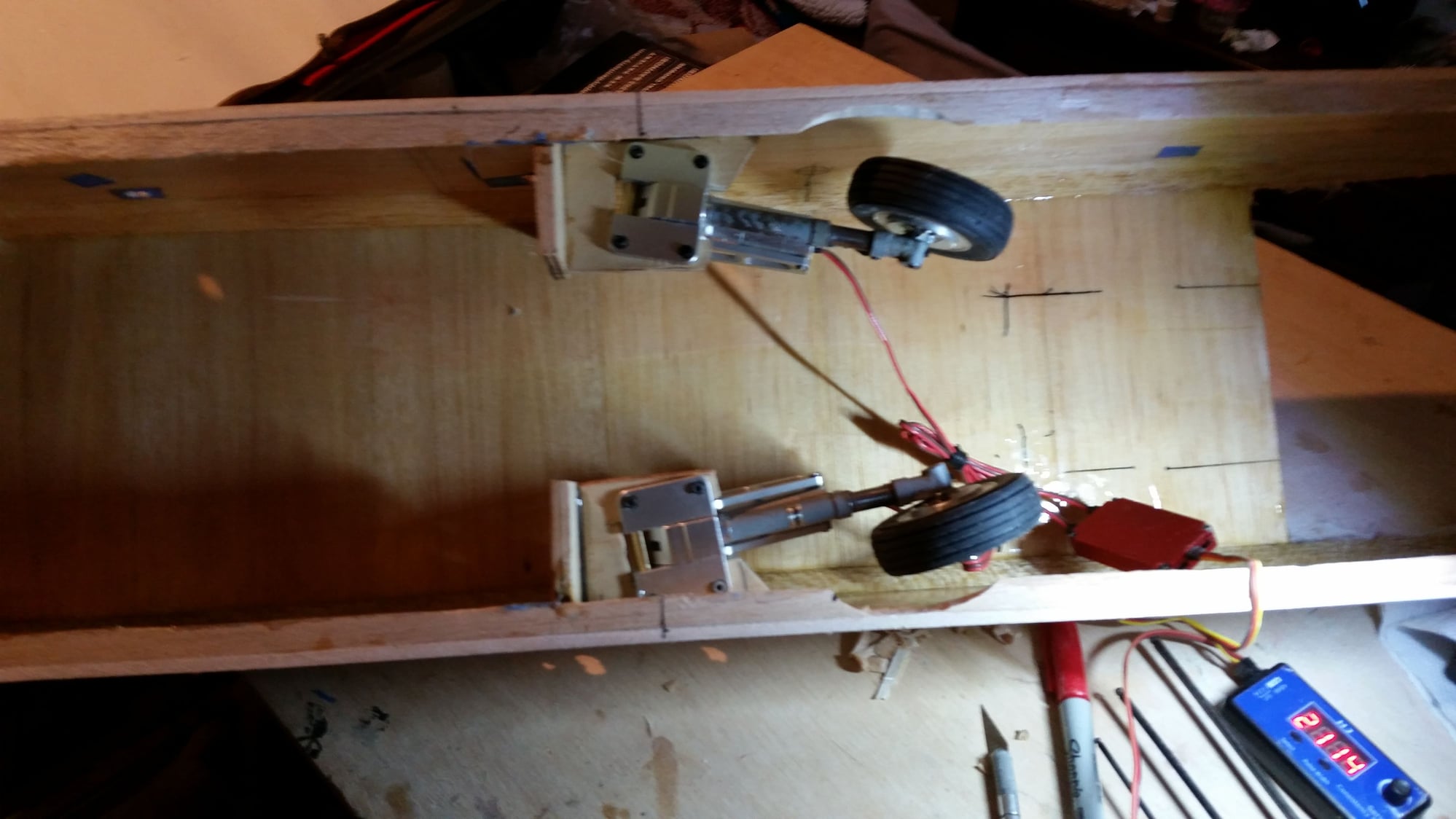
I installed one retract to check the clearances before doing the second.
I tilted and cambered the mounts to retract into the fuse entirely instead of making bubbles on the sides to accept them. This will make sanding the sides much easier. This is also the maximum spread I can give the main wheels and keep them from tilting.
Just visible forward of the retracted gear is the marked position of the front fuse section. I had intended going with a 50oz tank but it won't fit and allow the gear to retract. I ordered a 40oz tank but that may not fit either. I will try a 32oz one as soon as I get a chance. A 24oz tank will fit , so if necessary I will use a couple of tanks in series.
Next I will probably fit the front section but may go back and fit the wings next. Those are a "chicken and egg" situation as the wings have to be in place for the torque rods to go in the holes I provided, and simultaneously slip onto 5" of carbon rod on each side. I'm still pondering that. I think I may have a solution short of cutting off the torque rods.
The retracts are JP. The struts are Robart struts with about a 15deg angle on the axle. As far as I can tell no longer available, or at least not listed on their site. The brakes are Xicoy with 5mm threaded axels. It turns out the solution of the mix between SAE and metric was more simple than I thought. It is possible to tap the 3/16" axle hole in the Robart strut with a 5mm tap which then takes the threaded axle well. Those are installed with Loctite blue. The brakes are installed with a little JB weld behind the brake backplate to make up for the disparity between the backplate anti rotation lugs and the sides of the axle hub. I seems pretty solid.
John
 09-05-2020 | 03:01 PM
#27

Coming along nicely but looks on the complicated side. For 3 out of my 4 FS planes, down and welded were the answer! I ended up installing the 1/4" square carbon fiber rods for wing stiffeners. I cut a channel with my Dremel tool and then epoxied the rods in place. I did my best to install around the CG per your suggestion and I still am hopeful that my "aerobatics" won't be as stressful as yours. I also sanded a bevel into my ailerons and will install (temporarily) my Robart hinge points.
Waiting for the next installment of pictures as I am getting anxious to move on.
Waiting for the next installment of pictures as I am getting anxious to move on.
09-07-2020 | 08:27 AM
#29
Thread Starter
My Feedback: (13)
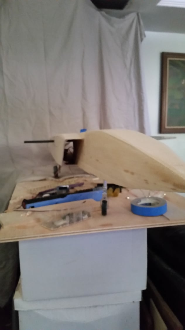
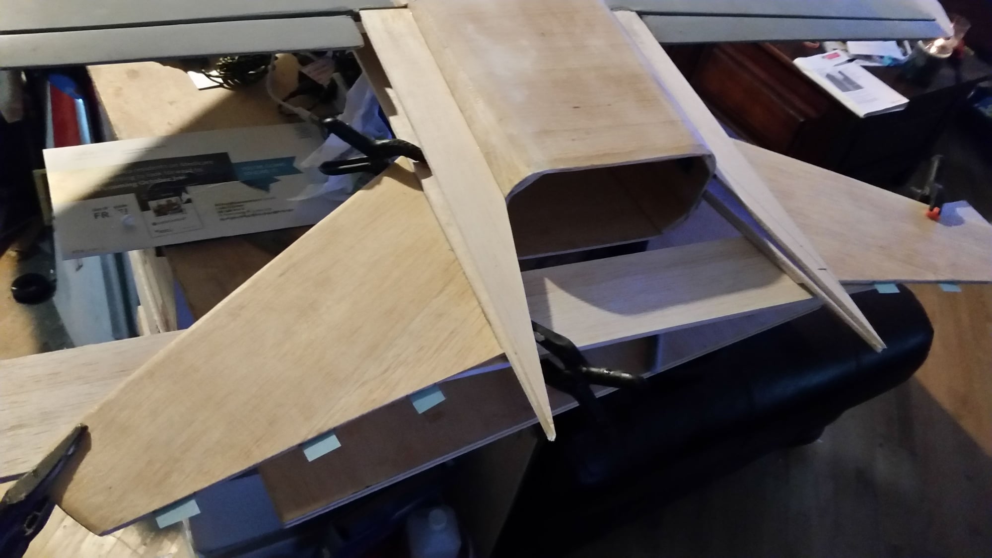
I got busy last night and sheeted most of the fuse.
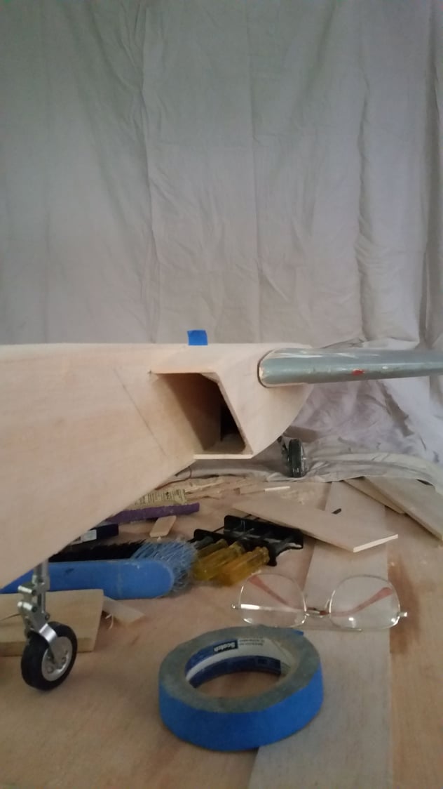
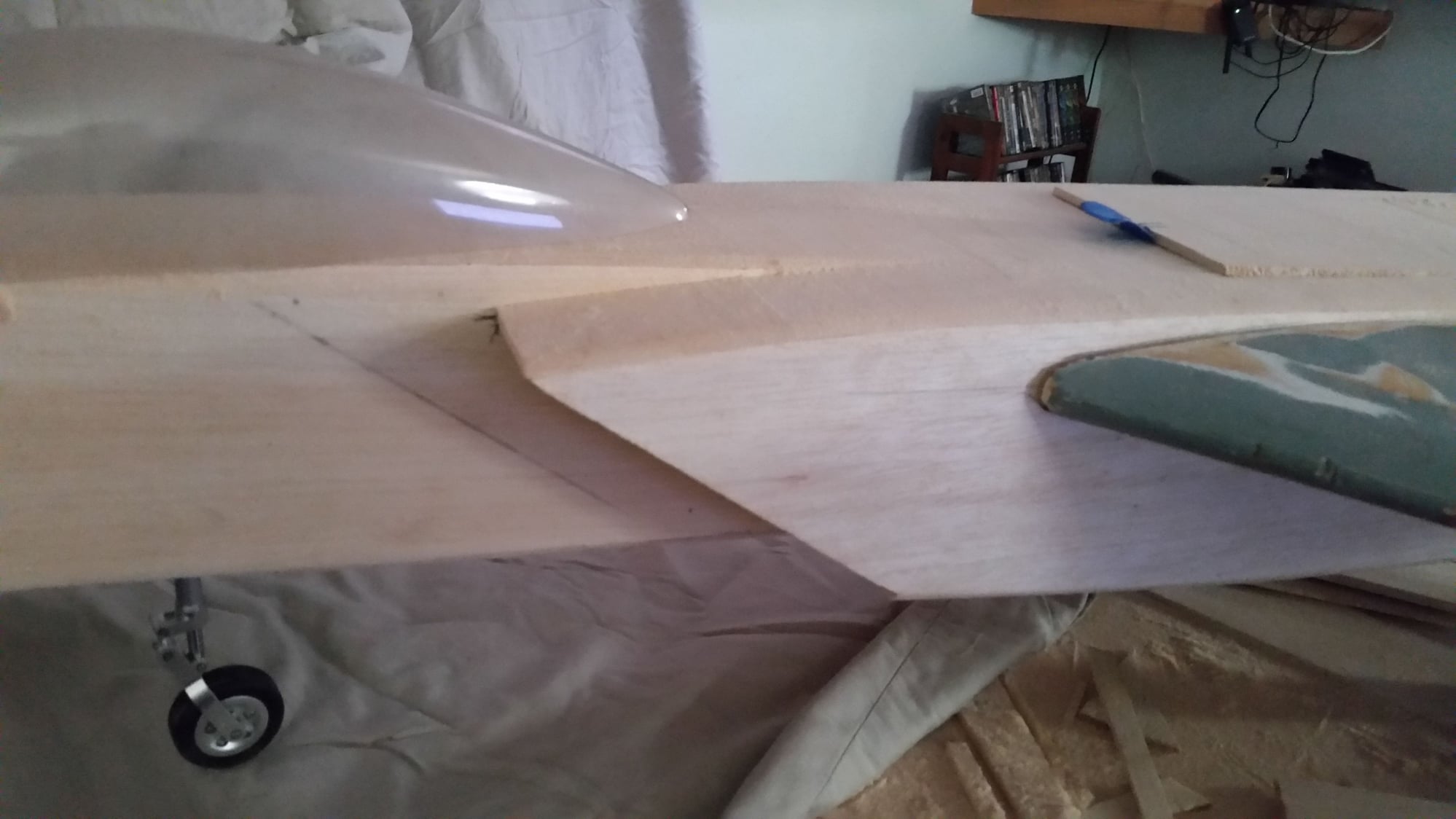
I also fitted one of the wings as you can see to test fit things. I think the inlets turned out well enough. I made a few changes, the largest of which is taking an inch out of the width of the fuse in order to narrow down the intakes a bit.
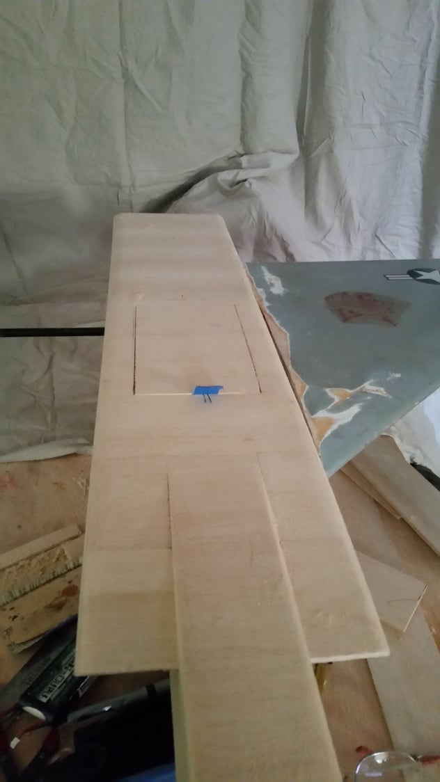
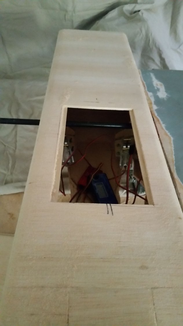
I cut in the top hatch which is for the fuel tank and electronics access.
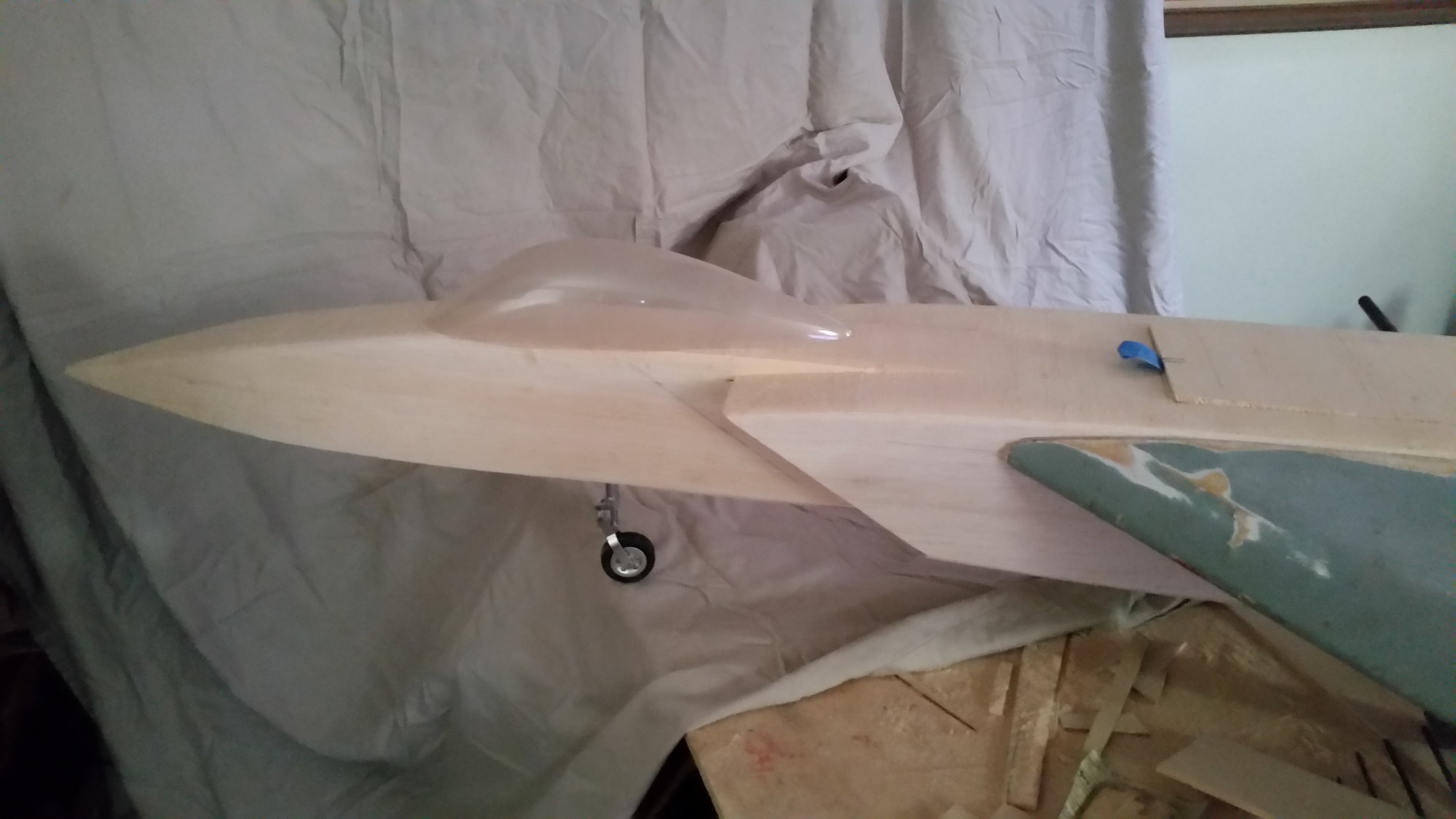
I also tested a canopy I had laying around to see how it looks. If you look at the side of the fuse you can make out the outline of where the inlets were supposed to extend to originally. I have lengthened the nose 3", because I think it looks better and to help counterbalance the turbine which I plan to mount as far to the rear as possible.
The next step is to attach both wings and build the stab booms. At this point I will try and decide how to go from two exhausts to one and still keep it looking good. I had thought to use the old ABS exhaust but narrowing down the fuse nixed that idea.
John
I also fitted one of the wings as you can see to test fit things. I think the inlets turned out well enough. I made a few changes, the largest of which is taking an inch out of the width of the fuse in order to narrow down the intakes a bit.
I cut in the top hatch which is for the fuel tank and electronics access.
I also tested a canopy I had laying around to see how it looks. If you look at the side of the fuse you can make out the outline of where the inlets were supposed to extend to originally. I have lengthened the nose 3", because I think it looks better and to help counterbalance the turbine which I plan to mount as far to the rear as possible.
The next step is to attach both wings and build the stab booms. At this point I will try and decide how to go from two exhausts to one and still keep it looking good. I had thought to use the old ABS exhaust but narrowing down the fuse nixed that idea.
John
09-17-2020 | 11:49 AM
#30
Thread Starter
My Feedback: (13)
Some more progress has been made! I decided to glass the outside of the fuse to add strength and fuel proofing, and as an aid to paint. That took a couple of days. I then attached the wings. I almost painted myself into a corner there. I had projections at 90 deg to one another where they were to slide together. I have a carbon fiber spar six inches into each wing and across the airframe. I also have aileron torque rods on each wing. I solved the problem by bending one of the torque rods enough to slide through a slightly enlarged hole in the airframe side, then straightened it back up again after install.
The servos are a little out of alignment as I had to install them in the blind. I had to reach in from the hatch and from the rear at the same time to glue them in place. This left my nose at the top of the middle of the airframe. I tried it with a mirror as a last resort and this is what I ended up with. They work fine so I'll leave them as is.
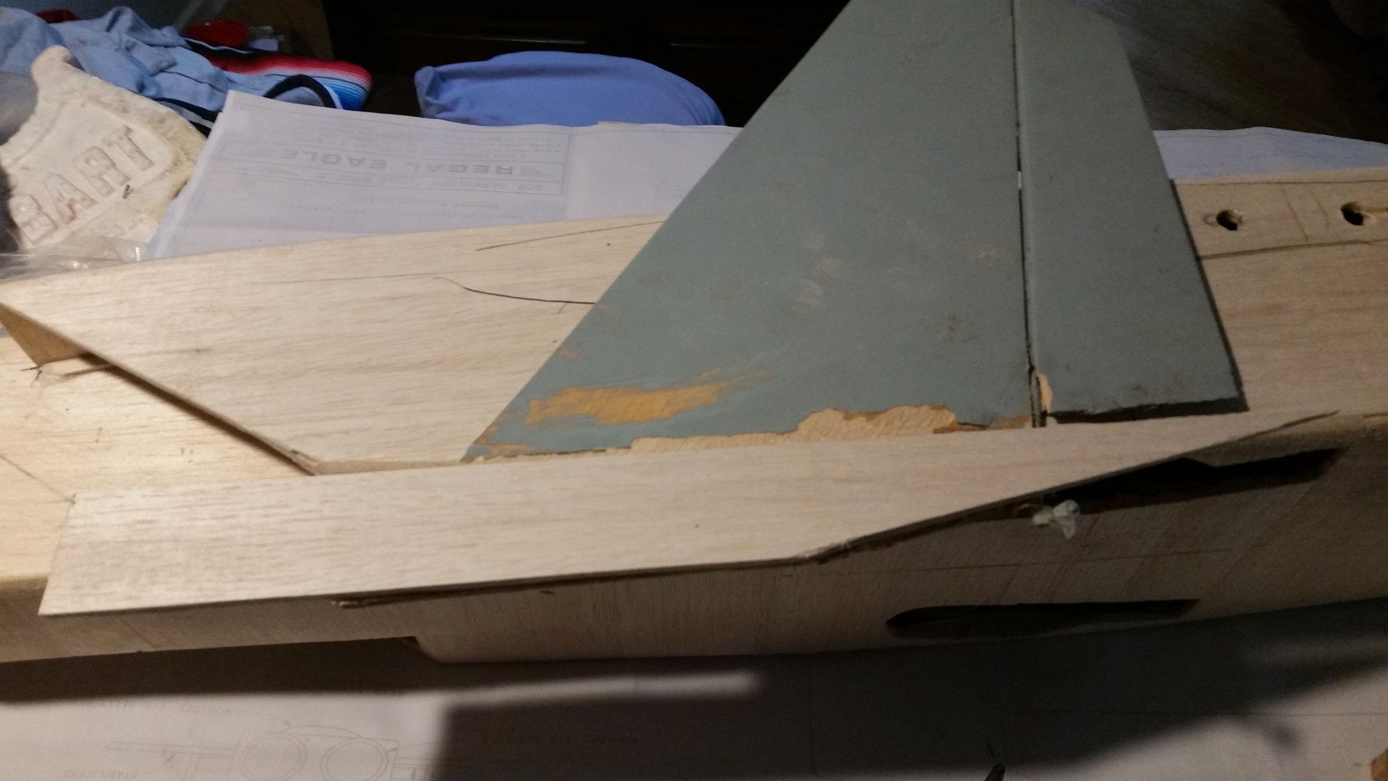
The next step was to build in place the booms.
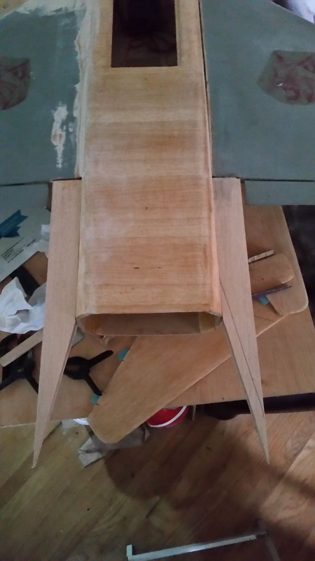
They build up against two alignment pegs in the side of the fuse. The horizontal stab glues to the bottom of the boom.
I used a sheet of balsa clamped to the stabs as the epoxy set to make sure the surfaces are in alignment with each other. The next step is to install the elevators and their torque rods, which I am awaiting in the mail, then the vertical stabs and rudders. The rudder servos are buried in the booms as well as their linkages and I will be working on those for the next couple of nights. I can then sheet the sides of the booms and the extension of the booms on the bottom of the wings. I decided the elevators I had hoped to salvage were not sufficient so I have made new ones. This brings the cost of this build up to about $95 less the hardware I am replacing and the electronics I decided to upgrade.
John
The servos are a little out of alignment as I had to install them in the blind. I had to reach in from the hatch and from the rear at the same time to glue them in place. This left my nose at the top of the middle of the airframe. I tried it with a mirror as a last resort and this is what I ended up with. They work fine so I'll leave them as is.
The next step was to build in place the booms.
They build up against two alignment pegs in the side of the fuse. The horizontal stab glues to the bottom of the boom.
I used a sheet of balsa clamped to the stabs as the epoxy set to make sure the surfaces are in alignment with each other. The next step is to install the elevators and their torque rods, which I am awaiting in the mail, then the vertical stabs and rudders. The rudder servos are buried in the booms as well as their linkages and I will be working on those for the next couple of nights. I can then sheet the sides of the booms and the extension of the booms on the bottom of the wings. I decided the elevators I had hoped to salvage were not sufficient so I have made new ones. This brings the cost of this build up to about $95 less the hardware I am replacing and the electronics I decided to upgrade.
John
09-19-2020 | 02:34 PM
#31
John: Something is different from what I have and from your pics above. It "seems" to me that the highest "stab" is actually higher than the trailing edge/aileron of the wing. My forward most dowel is almost an inch BELOW the trailing edge of the wing!! By any chance do you have the picture that shows the 2 dowels and the stabs upside down?? I also sent you an e-mail with my questions. Sorry to bug you and thank you for this building thread and pictures.
10-04-2020 | 07:24 AM
#32
Thread Starter
My Feedback: (13)
It's been a few weeks since I have been able to update things here due to computer troubles. I have made a bit of progress in that time.
One thing was to fit a trial canopy.
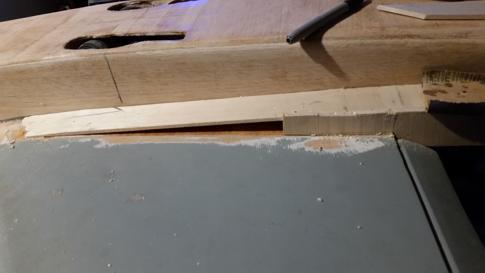
The next part of the process was to build the stabilizer booms. These have alignment pegs on the prints matching the alignment pegs for the wings to keep the angle between the wing and stabs correct. The bottom alignment boom part glues to the bottom of the pegs with the angle cut in the part even with the rear of the balsa fuse.
This bottom alignment piece gets sheeted completely over in the process while the top one is the finish surface of the boom.
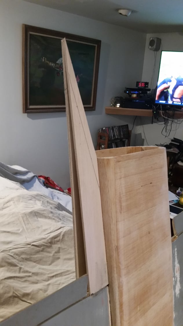
The top piece is cut and flushed to the top rear of the wing core. Then the bottom of the boom is extended along the bottom of the wing and terminates at the thickest part of the wing making a box structure. The horizontal stabs are glued to the bottom of the lower alignment piece then the box structure is built fore and aft of that. Since I am using torque rods for the elevators I don't sheet the lower aft portion of the boom till the torque rods and elevators are installed.
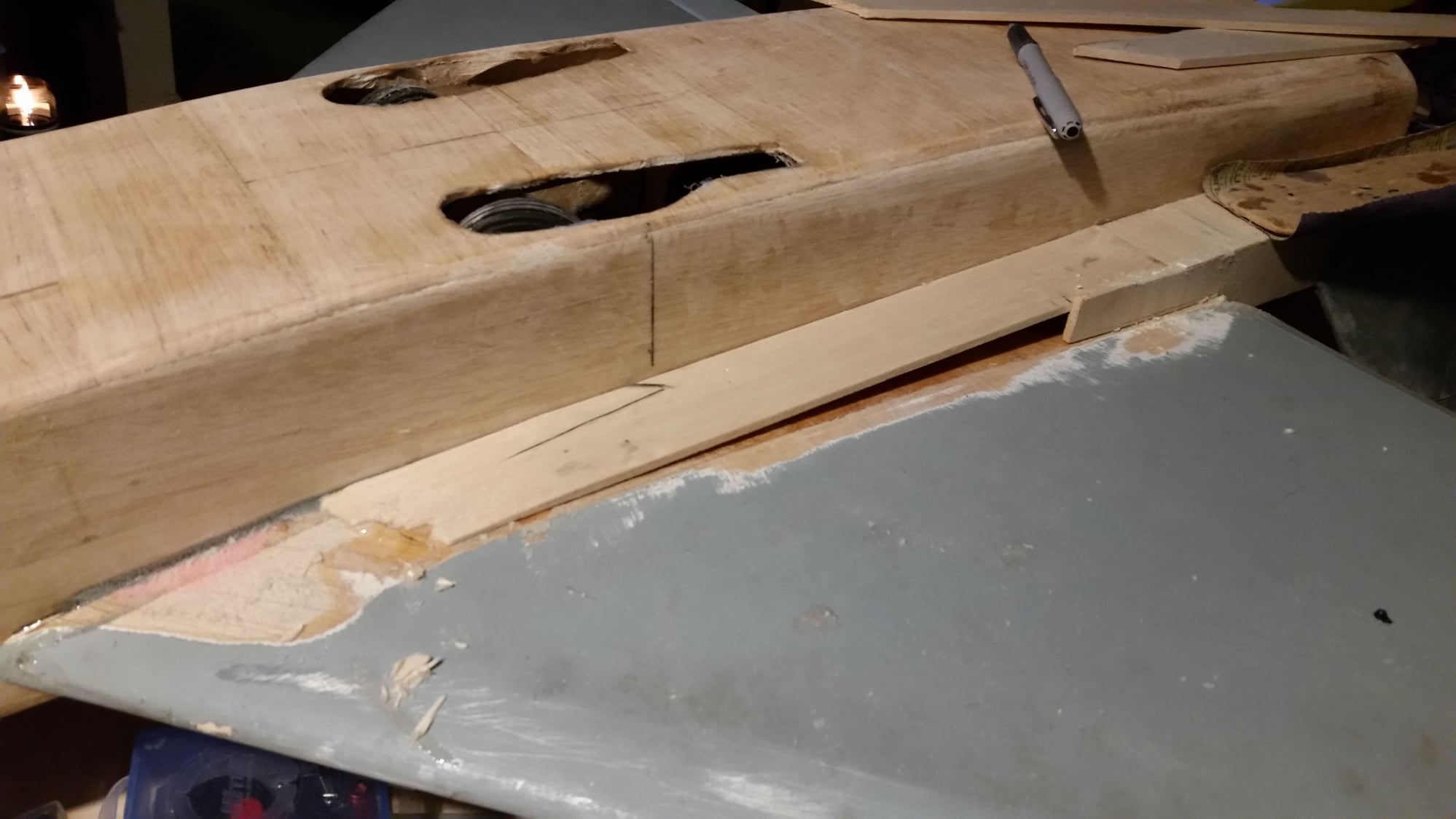

I used a straight edge across the hor stabs to ensure their alignment while the epoxy set.
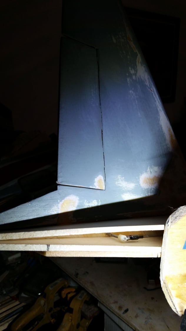
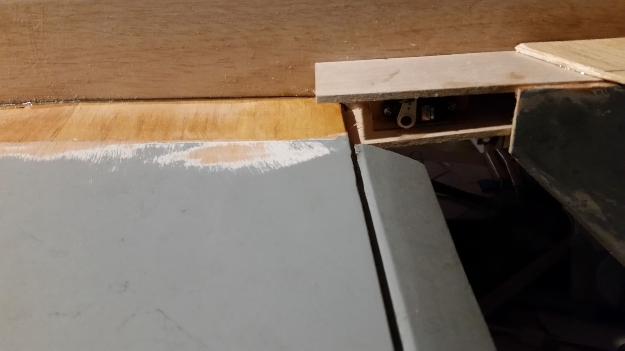
The fins are then glued to the outside of the box structure, and the servos for the rudders and linkages are installed inside the boom structure. I zeroed the servos during install as I would have to cut open the side of the boom to change their centering.
The last thing I have gotten done is the turbine mount at the rear.

This is not how I had envisioned the turbine install, but is a compromise to keep things accessible and not burn the tail off. I guess I will leave the rear open for flight as I have not figured a pretty solution for imitating a twin exhaust.
Right now wood costs have risen to $120. The plane is 71" long and 51" span. The weight is up to 11 pounds according to my fish scale with the turbine, retracts and all but the elevator servos installed. This means I will exceed my target, but not by too much.
John
One thing was to fit a trial canopy.
The next part of the process was to build the stabilizer booms. These have alignment pegs on the prints matching the alignment pegs for the wings to keep the angle between the wing and stabs correct. The bottom alignment boom part glues to the bottom of the pegs with the angle cut in the part even with the rear of the balsa fuse.
This bottom alignment piece gets sheeted completely over in the process while the top one is the finish surface of the boom.
The top piece is cut and flushed to the top rear of the wing core. Then the bottom of the boom is extended along the bottom of the wing and terminates at the thickest part of the wing making a box structure. The horizontal stabs are glued to the bottom of the lower alignment piece then the box structure is built fore and aft of that. Since I am using torque rods for the elevators I don't sheet the lower aft portion of the boom till the torque rods and elevators are installed.
I used a straight edge across the hor stabs to ensure their alignment while the epoxy set.
The fins are then glued to the outside of the box structure, and the servos for the rudders and linkages are installed inside the boom structure. I zeroed the servos during install as I would have to cut open the side of the boom to change their centering.
The last thing I have gotten done is the turbine mount at the rear.
This is not how I had envisioned the turbine install, but is a compromise to keep things accessible and not burn the tail off. I guess I will leave the rear open for flight as I have not figured a pretty solution for imitating a twin exhaust.
Right now wood costs have risen to $120. The plane is 71" long and 51" span. The weight is up to 11 pounds according to my fish scale with the turbine, retracts and all but the elevator servos installed. This means I will exceed my target, but not by too much.
John
Last edited by john491; 10-04-2020 at 07:26 AM.
10-13-2020 | 03:10 PM
#33
Thread Starter
My Feedback: (13)
OK, the fish scale is a little off. I guess it was calibrated so you could brag on your catch.
Right now, if the load cells are to be believed, I am at 9.66 pounds with the X-45 turbine installed, the gear installed, all the servos installed, the fuel tank in place but no UAT at the moment and no batteries, using .83 pounds of nose weight so that the plane is at the proper CG. The nose weight needed may change by where I locate the batteries. I guess I lightened up the nose too much. I have also got the first two coats of primer on the plane. First was a sandable which was almost completely removed, the second as a base for painting. I plan on rattle can from Home Depot with a clear gloss on top. Decorations planned to be the Redhawk scheme from Callie Graphics. The pilot and canopy also still to be added. The scale of the plane works out to 1/10th scale.
I guess I will come close to the target weight after all.
John
10-14-2020 | 03:02 AM
#34

My Feedback: (21)
Great job on the build and use of some of the old parts. I enjoy the box of sticks build threads. Takes me back to when I rebuilt my HP Jets F-86 after a midair
F-86 Crash and rebuild
Joe
F-86 Crash and rebuild
Joe
10-16-2020 | 11:45 AM
#35
Thread Starter
My Feedback: (13)
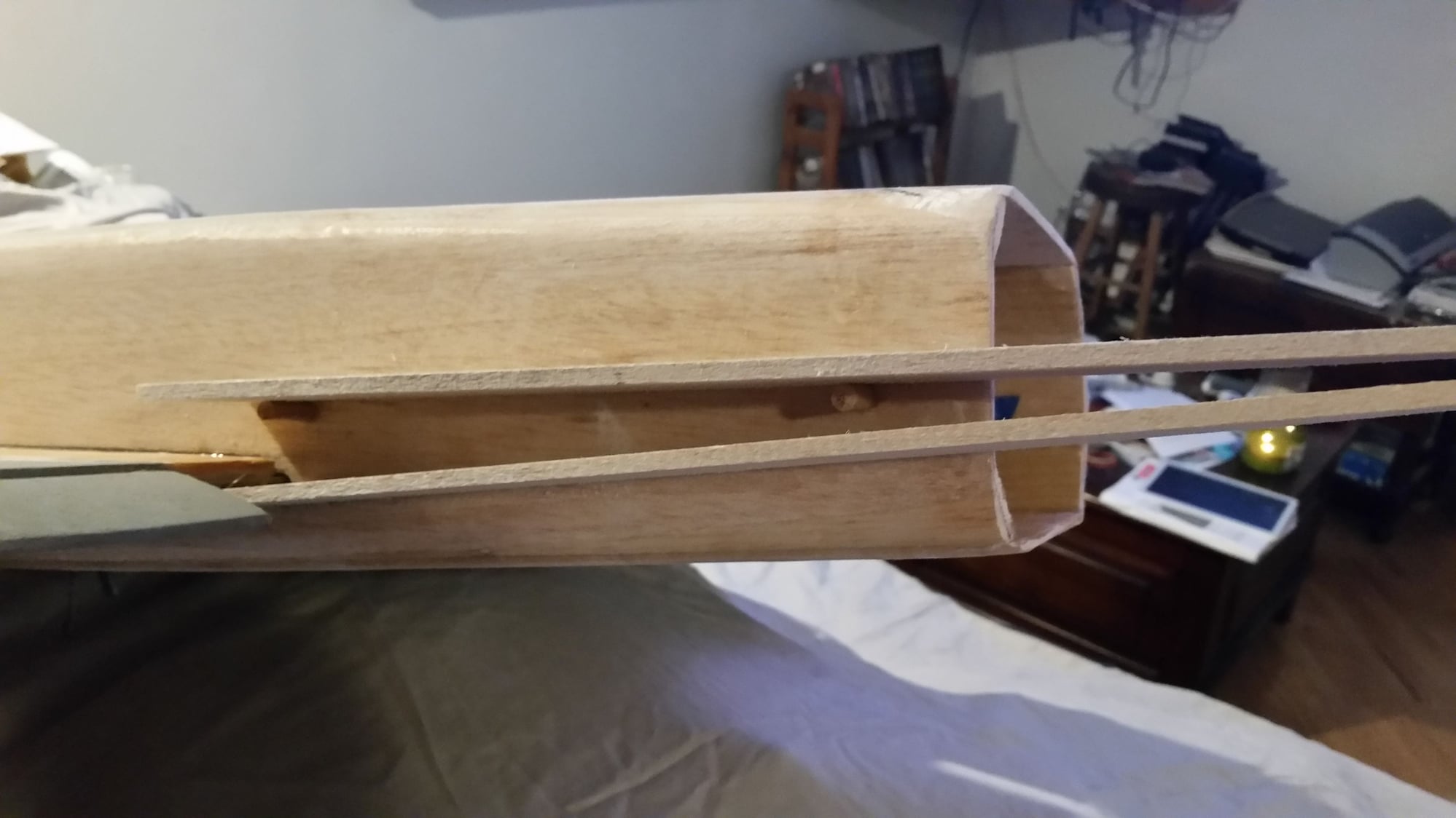
After dithering around for a week I decided to simply go ahead and do the nose weight so I could finish shaping the nose. I set up an old servo box on the nose over where I planned on placing the lead and added it to the box one piece at a time until the proper CG was reached.
The weights are lead fishing net weights available at the local fishing supply store three blocks away. They are .02# apiece. It took a total of .89# to achieve the CG with most of the heavy stuff in the plane. I had left an opening in the nose to install them. I mixed up an oz of finishng resin, dumped in the weights and stirred till they were totally covered and poured them in the nose.
I have used this method in the past and the weights resist removal even with a pair of channel locks. I can now sheet the bottom of the nose and shape it to match the topside. I attached and img file to show what this looks like, but don't know if it will show. The profile was taken at 100mm from the tip of the nose. I plan on the bottom side matching.
The turbine is mounted at the extreme rear of the fuse. If anyone wants to do a conversion to match this one I hope this will serve as a guide.
12-17-2021 | 02:43 PM
#36
Thread Starter
My Feedback: (13)
I finished the plane about a year ago.
Final finish
The maiden went exceptionally well in the beginning.
It was powered by a XiCoy X-45. I had a 40 oz DuBro tank and a two oz header which I calculated as enough for a 7 minute flight. Total weight dry was 13.24 #. I rotated after about 100' from our paved runway and climbed out as I normally do. I was at full power as I made the initial turn, cut that back to 1/2 power on the downwind run, then decided the plane liked about 60% power for cruising. As I made each pass down the runway I increased the throttle about 10%. On the third or fourth pass my spotter called out he thought he saw flutter in the left aileron. I made a pass at a slightly reduced throttle and did not see any flutter so I went back to speeding it up.
On the sixth or seventh pass the right horizontal stab broke off taking its elevator with it.
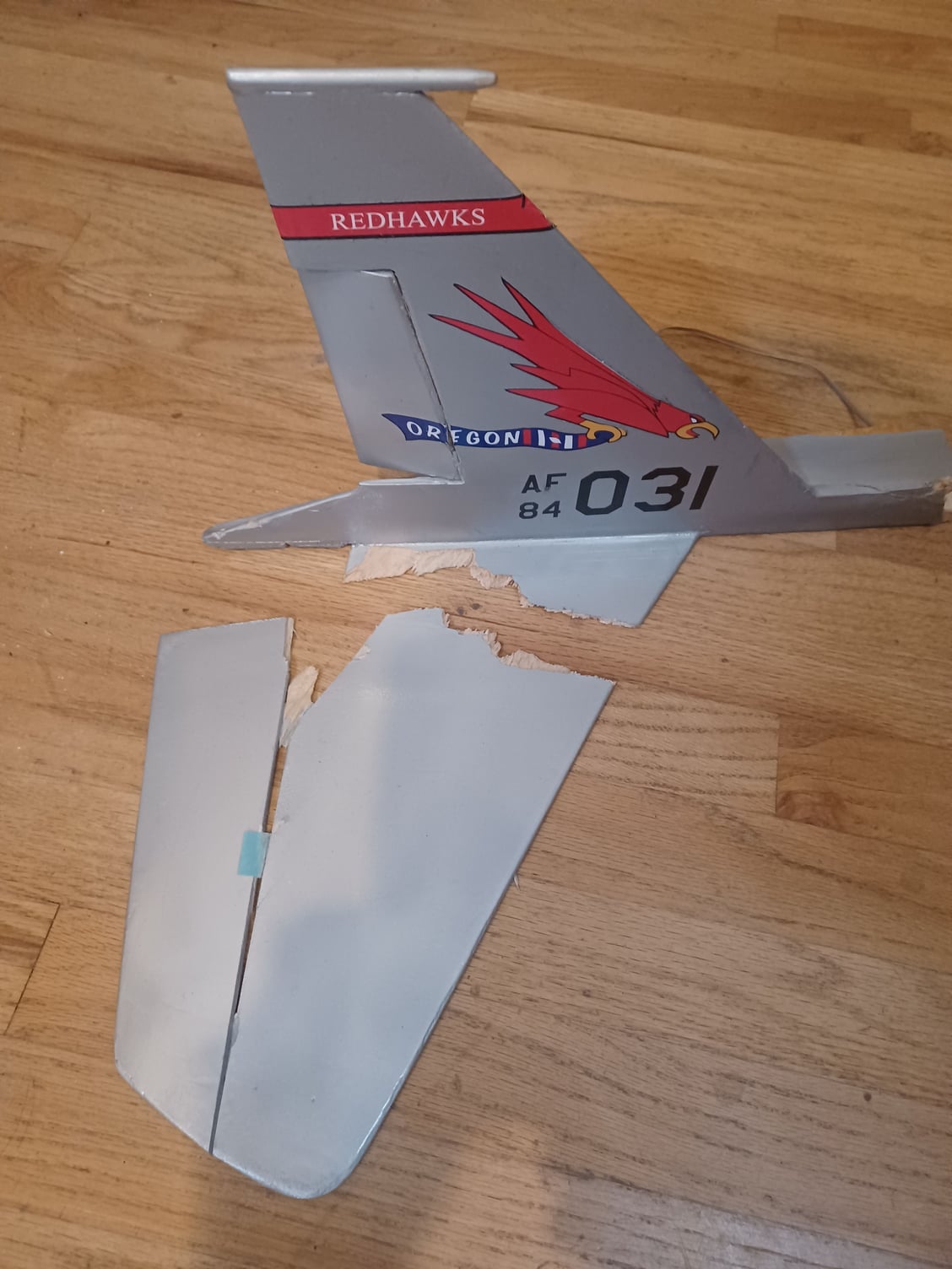
Needless to say things went downhill from there. I was at about 50' heading toward a lake, then a fire station, so I had to turn immediately. I can tell you that the plane does not turn at all well with half the elevator. My initial reaction to a part falling off the plane was to reduce power so nothing else would depart the plane, and that reaction was probably the reason for its demise. After that initial turn I was unable to keep it in the air and it rolled over and dove into the ground.
Lots of pieces. Everything forward of the intakes was reduced to pieces no larger than a quarter except for the nose retract.
I haven't gotten the electronics for the turbine to come back to life, so I don't have the saved info from the turbine. The case is undamaged. I broke the strap and slightly damaged the FOD screen.
I now have the same parts I started this project with and am debating with myself on building another.
The cons of the plane are that it is a little difficult to see its attitude after about 1500 feet, and it did not finish the flight. It is also a draggy airframe.
It flew well at about 80% throttle at I would guess was about 110 mph. I would guess the top speed with this power system would be about 130. Its top speed was on a par with a 100-120 EDF on 12s.
John
Final finish
The maiden went exceptionally well in the beginning.
It was powered by a XiCoy X-45. I had a 40 oz DuBro tank and a two oz header which I calculated as enough for a 7 minute flight. Total weight dry was 13.24 #. I rotated after about 100' from our paved runway and climbed out as I normally do. I was at full power as I made the initial turn, cut that back to 1/2 power on the downwind run, then decided the plane liked about 60% power for cruising. As I made each pass down the runway I increased the throttle about 10%. On the third or fourth pass my spotter called out he thought he saw flutter in the left aileron. I made a pass at a slightly reduced throttle and did not see any flutter so I went back to speeding it up.
On the sixth or seventh pass the right horizontal stab broke off taking its elevator with it.
Needless to say things went downhill from there. I was at about 50' heading toward a lake, then a fire station, so I had to turn immediately. I can tell you that the plane does not turn at all well with half the elevator. My initial reaction to a part falling off the plane was to reduce power so nothing else would depart the plane, and that reaction was probably the reason for its demise. After that initial turn I was unable to keep it in the air and it rolled over and dove into the ground.
Lots of pieces. Everything forward of the intakes was reduced to pieces no larger than a quarter except for the nose retract.
I haven't gotten the electronics for the turbine to come back to life, so I don't have the saved info from the turbine. The case is undamaged. I broke the strap and slightly damaged the FOD screen.
I now have the same parts I started this project with and am debating with myself on building another.
The cons of the plane are that it is a little difficult to see its attitude after about 1500 feet, and it did not finish the flight. It is also a draggy airframe.
It flew well at about 80% throttle at I would guess was about 110 mph. I would guess the top speed with this power system would be about 130. Its top speed was on a par with a 100-120 EDF on 12s.
John
Last edited by john491; 12-17-2021 at 02:47 PM. Reason: additional info


