


Trident airliner scratch build
 02-17-2021 | 02:25 PM
#1

Thread Starter

I saw Steve Rickett's Comet fly at several model shows and decided, "I want one. I want a big jet airliner show model."
I considered the options and, being a believer in KISS, decided on a trijet with one engine.
So there's the B727 - been done as a kit, not my scene, the L1011 Trisar, been done as a kit, nearly bought one.
Or the Hawker Siddeley HS-121 Trident. Now nobody has ever built and flown a model Trident.
I obtained a small drawing off the internet, no detail shown, but I wasn't planning on detail just a big show model, not a scale competition type. I looked at various sizes and decided on a scale of 1/7.2 - just under seventh scale, same as Steve's Comet. I already had a Merlin 160 that should do. So I thought about it for about ten years, then went to photograph the Trident 2E at Duxford. I also had second thoughts on power and bought a Jets Munt 200.
A few more years of planning but no action went by, my age passed 70, so I'm on borrowed time, I realised that a big Trident was beyond capabilities so after taking advice from Steve Rickett I consulted a professional.
In an extensive discussion with Phil Clark of Fighteraces in October last year I explained what I wanted, he explained what was practical and he asked some difficult questions.
"What wing sections?"
"Duh! Dunno."
The Trident was designed to cruise at mach 0.9 so maybe the full size sections are not relevant.
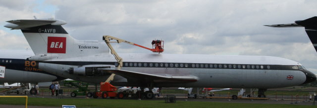
Trident in BEA introductory colour scheme
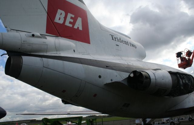
Will a model engine fit without a tailpipe?
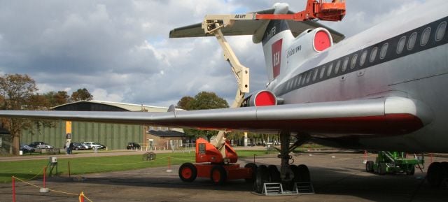
The wing has an obvious discontinuity on the top surface.
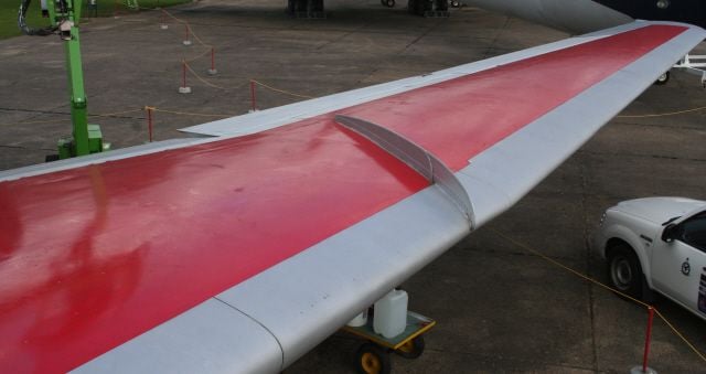
There is an odd change of section/taper/thickess a third of the way out.
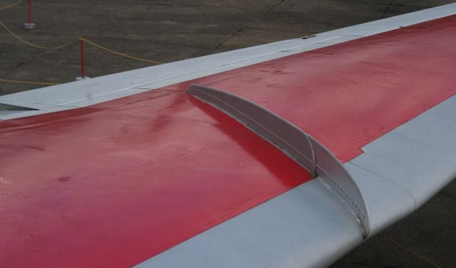
The discontinuity is at angle angle to the wing fence.
I went home to think about it, came up with an idea or two for building the wing, but would they work? One way to find out; build a test wing to a small scale.
I looked at the photos again and gave it some thought and decided that I could cut the inner panel from foam and sheet it, then add a built up outer panel.
I decided on NACA 0013 root section at the fuselage side, blended during foam cutting into NACA 33012 at the discontinuity. From there out would be a built up panel using laser cut ribs and spars with the same 33012 at its root, and the same section thinned to 10% thick at the tip rib. The NACA 5-digit section don't have much moment so don't load the tail too much.
So I could build a look-alike wing, maybe, but would it fly? I could find that out too if I added a representative tail and rudimentary fuselage, and an engine. That would tell me if it would fly, how it might handle, where a good CG might be, and many other answers.
Back in 1972 (while I was at college) G-ARPI crashed near Staines. It entered a deep stall due to premature droop retraction and could not recover.
My model, even the big one, would not have droop or slats as recommended by Phil Clark. So would the model deep stall?
Well the small proof-of-concept model might tell me that as well.
So I decided on a crude flying model to a scale of 1/20.
My scaling spreadsheet gave me a wing area of 3.5 sq ft and a target weight of 3 kg, 6.5 lb and a wingspan of 59 inches.
So that's what this thread is about. a twentieth scale Trident built as simply as possible, with no flaps, no moving tailplane, no retracts, and my latest new toy, an Xicoy X45 pushing it along.
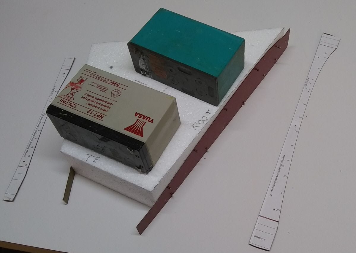
Here's the first stage, cutting a bit of foam to the trial sections.
I considered the options and, being a believer in KISS, decided on a trijet with one engine.
So there's the B727 - been done as a kit, not my scene, the L1011 Trisar, been done as a kit, nearly bought one.
Or the Hawker Siddeley HS-121 Trident. Now nobody has ever built and flown a model Trident.
I obtained a small drawing off the internet, no detail shown, but I wasn't planning on detail just a big show model, not a scale competition type. I looked at various sizes and decided on a scale of 1/7.2 - just under seventh scale, same as Steve's Comet. I already had a Merlin 160 that should do. So I thought about it for about ten years, then went to photograph the Trident 2E at Duxford. I also had second thoughts on power and bought a Jets Munt 200.
A few more years of planning but no action went by, my age passed 70, so I'm on borrowed time, I realised that a big Trident was beyond capabilities so after taking advice from Steve Rickett I consulted a professional.
In an extensive discussion with Phil Clark of Fighteraces in October last year I explained what I wanted, he explained what was practical and he asked some difficult questions.
"What wing sections?"
"Duh! Dunno."
The Trident was designed to cruise at mach 0.9 so maybe the full size sections are not relevant.
Trident in BEA introductory colour scheme
Will a model engine fit without a tailpipe?
The wing has an obvious discontinuity on the top surface.
There is an odd change of section/taper/thickess a third of the way out.
The discontinuity is at angle angle to the wing fence.
I went home to think about it, came up with an idea or two for building the wing, but would they work? One way to find out; build a test wing to a small scale.
I looked at the photos again and gave it some thought and decided that I could cut the inner panel from foam and sheet it, then add a built up outer panel.
I decided on NACA 0013 root section at the fuselage side, blended during foam cutting into NACA 33012 at the discontinuity. From there out would be a built up panel using laser cut ribs and spars with the same 33012 at its root, and the same section thinned to 10% thick at the tip rib. The NACA 5-digit section don't have much moment so don't load the tail too much.
So I could build a look-alike wing, maybe, but would it fly? I could find that out too if I added a representative tail and rudimentary fuselage, and an engine. That would tell me if it would fly, how it might handle, where a good CG might be, and many other answers.
Back in 1972 (while I was at college) G-ARPI crashed near Staines. It entered a deep stall due to premature droop retraction and could not recover.
My model, even the big one, would not have droop or slats as recommended by Phil Clark. So would the model deep stall?
Well the small proof-of-concept model might tell me that as well.
So I decided on a crude flying model to a scale of 1/20.
My scaling spreadsheet gave me a wing area of 3.5 sq ft and a target weight of 3 kg, 6.5 lb and a wingspan of 59 inches.
So that's what this thread is about. a twentieth scale Trident built as simply as possible, with no flaps, no moving tailplane, no retracts, and my latest new toy, an Xicoy X45 pushing it along.
Here's the first stage, cutting a bit of foam to the trial sections.


The following users liked this post:
ps2727 (02-17-2021)
02-17-2021 | 03:56 PM
#3
Thread Starter
Thanks Paul.
I'm not as sophisticated as you, with your glass vac-moulding, or Javad (scratch Phantom) with his scale rivet and panel line detail on a fab spray-paint job.
I draw in an old 2-D CAD package called Design-CAD by a company called ViagraFix, sorry no, ViaGrafix. I still use version DesignCAD 97 as I'm too old to learn new tricks.
I have a small laser cutter in the garage and it's great to draw something in the study then take a memory stick to the garage and cut it out.
I use a version of Compufoil over 20 years old to draw my wing ribs (brilliant) and cut them on the laser cutter (PFM).
I've been taking photos as I go so I'll post some more tomorrow.
02-18-2021 | 08:32 AM
#5
Thread Starter
The Trident wing inner panels were hot wire cut from foam. I was working alone due to lockdown: nobody on the other end of the bow, so it wasn't easy. I made a lot of scrap but also ended up with two usable panels. The root rib is NACA 0013 (symmetrical 13% thick) and that blended to the section at the panel join to NACA 33012, which is a 5 digit NACA with a low pitching moment and 12% thick. Since the join is skewed away from the centreline by about 30 degrees the airflow will see this as an even thinner section. I use templates made from plastic laminate (Formica). I built in 1.6 degrees of washout in the cut.
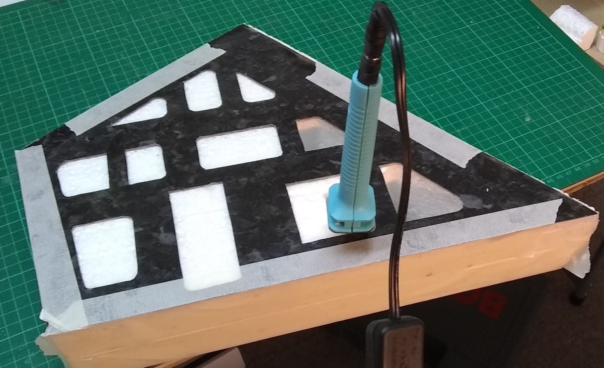
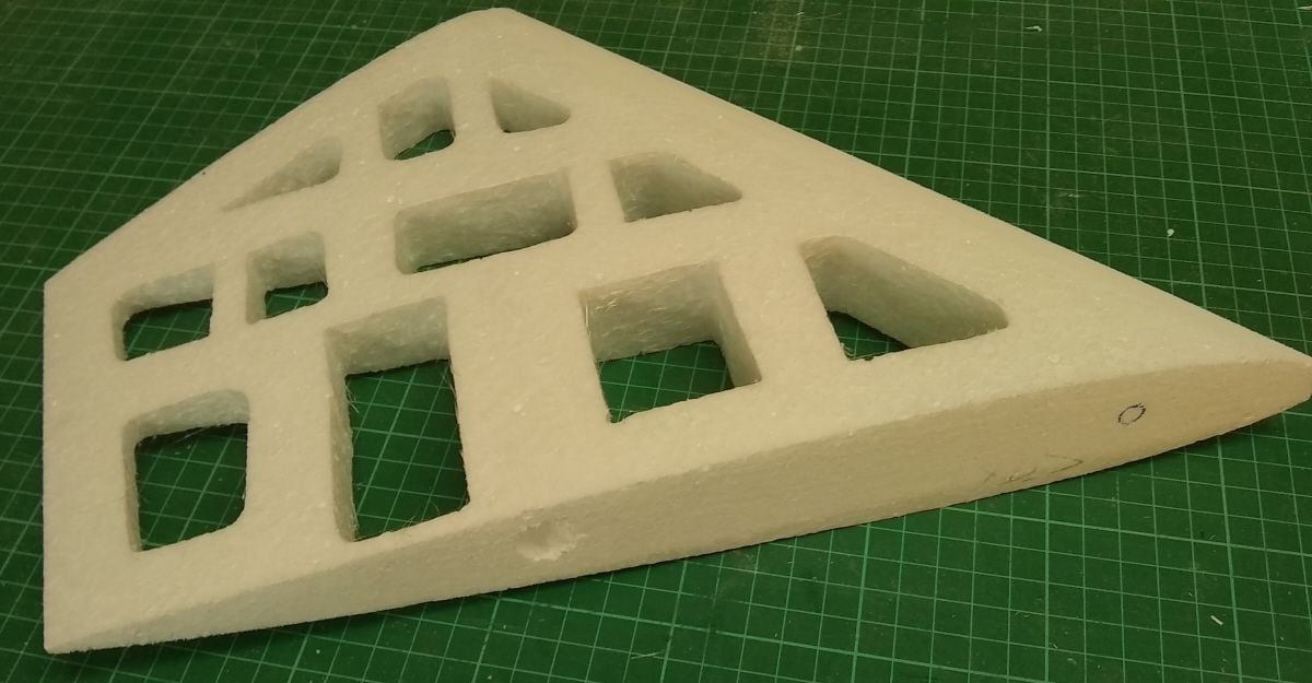
I made two identical plastic laminate templates matching the planform and used them to make cutouts in the panels using a foam cutting wand bought off ebay.
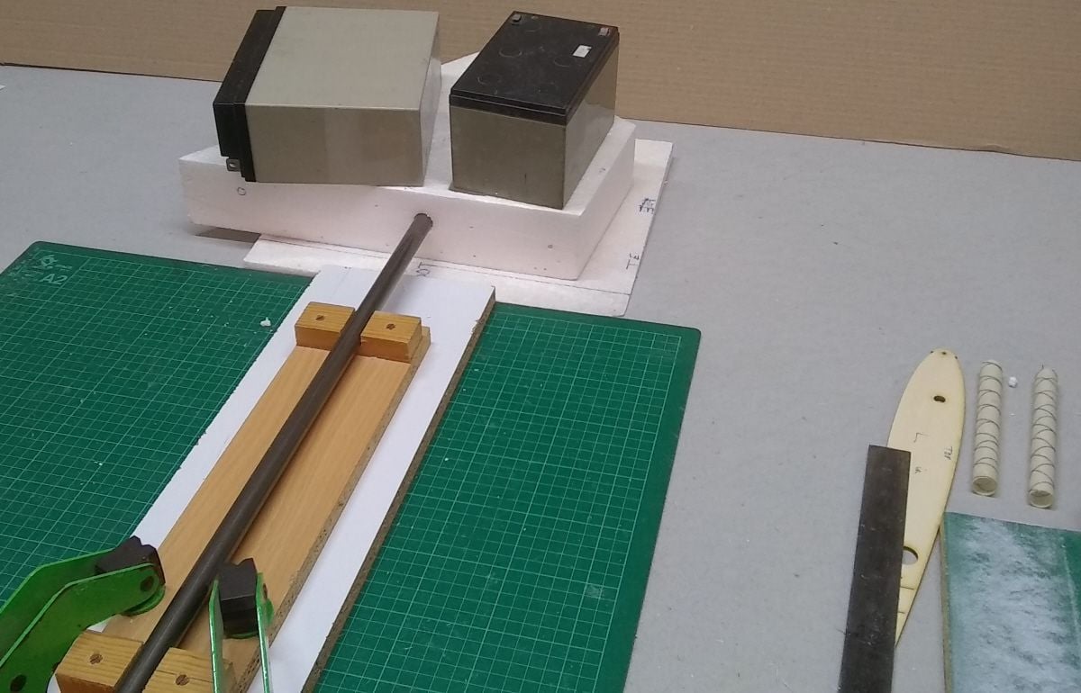
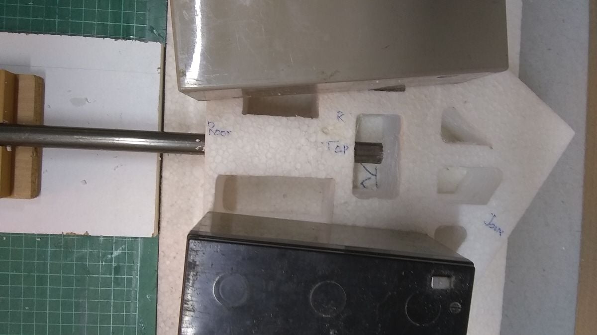
I used a sanding block to cut 4 degrees dihedral into the root face and then made a foam ramp at 4 degrees to support the panels while I bored holes, using a sharpened serrated steel tube, for the wing joiner.
A 4" long hot wand cut the holes right through
Dihedral sanded into root. Hole bored for wing joiner.
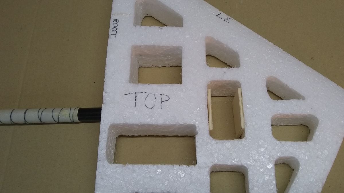
14mm carbon tube within home-made epoxy/glasscloth sleeves.
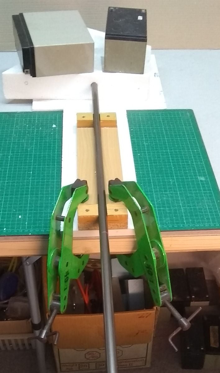
boring!
boring
Bored!
I made two identical plastic laminate templates matching the planform and used them to make cutouts in the panels using a foam cutting wand bought off ebay.
I used a sanding block to cut 4 degrees dihedral into the root face and then made a foam ramp at 4 degrees to support the panels while I bored holes, using a sharpened serrated steel tube, for the wing joiner.
A 4" long hot wand cut the holes right through
Dihedral sanded into root. Hole bored for wing joiner.
14mm carbon tube within home-made epoxy/glasscloth sleeves.
boring!
boring
Bored!
02-18-2021 | 10:12 AM
#6
Thread Starter
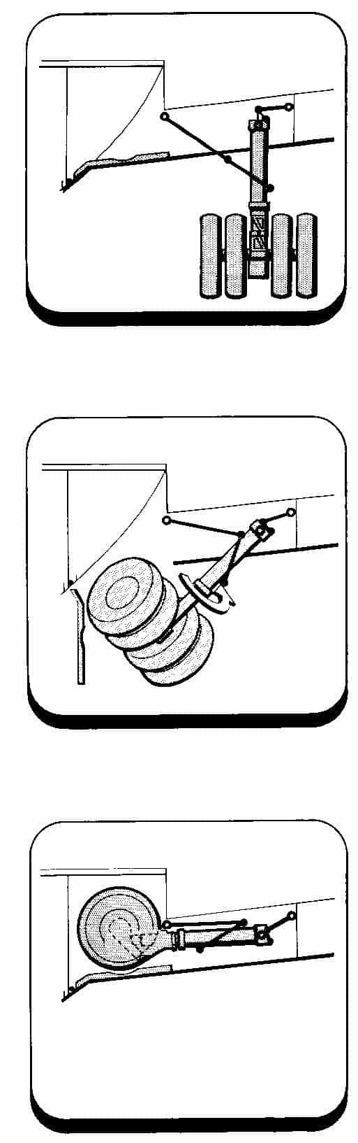
I saw a set of retracts that looked suitable for the mini Trident as they are "twist and turn".
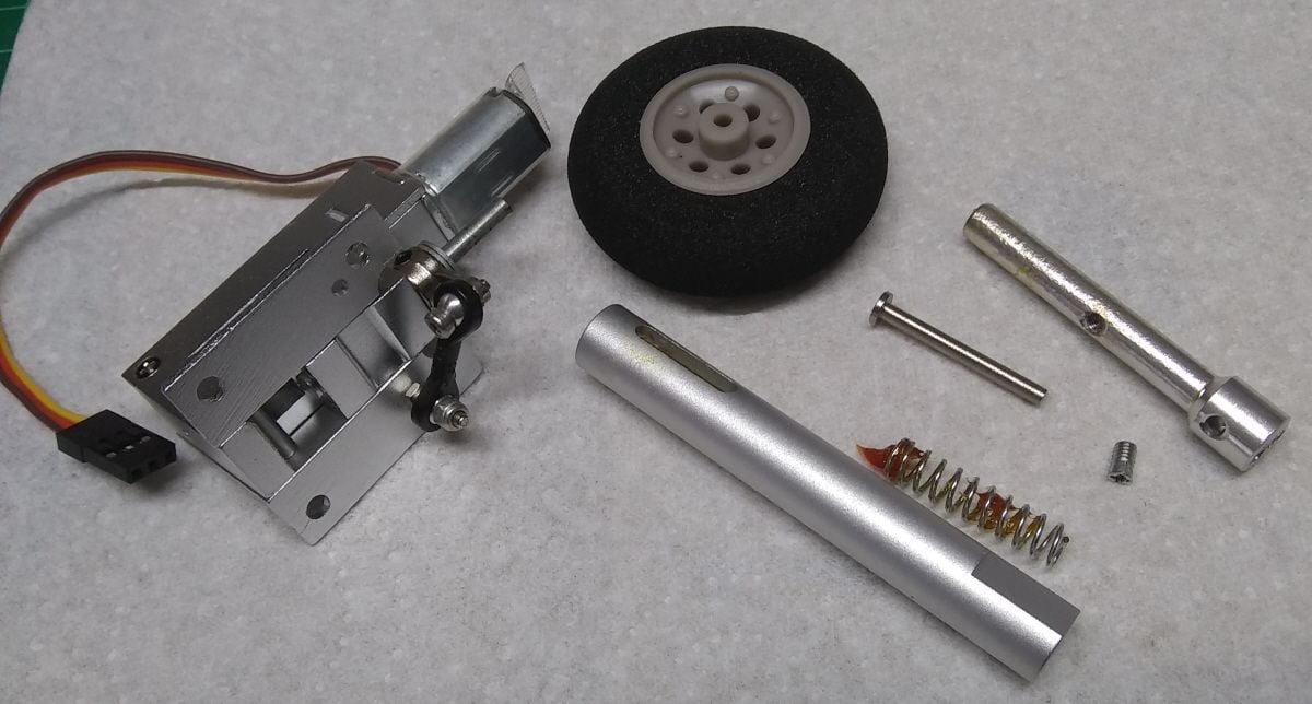
A retract unit stripped as far as I know how.
The legs on the full size Trident rotate as they retract such that the wheels stow with the axles parallel to the fuselage, just inside the fuselage.
All I'd need to do was replace the axle with a long axle with two wheels on each side.
Unfortunately these have a retract angle of 100 degrees or so. Ideally I'd use 85 degree retracts but 90 might do.
Anyone know how these things work? Is it possible to alter the end stops?
I am reluctant to take them apart without some idea of what I'm doing.
I decided to build with fixed gear. To change I'd need to hack out the mounting plates I've already fitted and make up new mountings.
A retract unit stripped as far as I know how.
All I'd need to do was replace the axle with a long axle with two wheels on each side.
Unfortunately these have a retract angle of 100 degrees or so. Ideally I'd use 85 degree retracts but 90 might do.
Anyone know how these things work? Is it possible to alter the end stops?
I am reluctant to take them apart without some idea of what I'm doing.
I decided to build with fixed gear. To change I'd need to hack out the mounting plates I've already fitted and make up new mountings.
Last edited by alasdair; 02-18-2021 at 11:11 AM. Reason: spelling
02-18-2021 | 10:26 AM
#7

I saw a set of retracts that looked suitable for the mini Trident as they are "twist and turn".
A retract unit stripped as far as I know how.
Trident retracts
The legs on the full size Trident rotate as they retract such that the wheels stow with the axles parallel to the fuselage, just inside the fuselage.
All I'd need to do was replace the axle with a long axle with two wheels on each side.
Unfortunately the retract angle is 100 degrees or so. Ideally I'd use 85 degree retracts but 90 might do.
Anyone know how these things work? Is it possible to alter the end stops?
I am reluctant to take them apart without some idea of what I'm doing.
I decided to build with fixed gear. To change I'd need to hack out the mounting plates I've already fitted and make up new mountings.
02-18-2021 | 11:16 AM
#8
Thread Starter
Hi David,
While it is said that when heavy the Trident 1C used the curvature of the earth to get airborne, I'm doing a 2E which had much better performance.
Not only that, I'm using a 45N engine in a 3 kg (dry) aeroplane!
It worries me. I'd better turn it down to 30N.
While it is said that when heavy the Trident 1C used the curvature of the earth to get airborne, I'm doing a 2E which had much better performance.
Not only that, I'm using a 45N engine in a 3 kg (dry) aeroplane!
It worries me. I'd better turn it down to 30N.
02-18-2021 | 11:33 AM
#9
Glad you appreciate the good natured rivalry, Alisdair. It was always a point of discussion, humour, as we taxied out at LHR in a VC10 for a long night sector to see all the Tridents parked for the night !
Great shame the Trident was screwed by the. BEA board ,( as was the VC10 by the BOAC board) constantly changing its spec. otherwise a technically superb aeroplane could have rivalled the B727.
and if you think the Trident came off the earth at a tangent, you never flew the Victor 1 tanker !
The biggest hindrance to British airliner design POLITICS !
Last edited by David Gladwin; 02-18-2021 at 11:40 AM.
 02-18-2021 | 03:15 PM
#11
Thread Starter
Hi Dave,
The retracts ARE a bit light. I think the pins are 3mm. The spec said "for models up to 3 kg."
But I bought them anyway to see how they could be fitted, how they moved and worked just to get an idea of how the big ones would need to be made. Until I made the foam panels and held those units up to them I had no clear idea of the space available, and the space required..
They don't have the correct retract angle anyway, but now I know what I need.
It will have simple fixed U/C and three small wheels, no brakes but will have nosewheel steering. It's just a proof of concept model.
I'll be lucky if it flies, and is controllable, and tells me what CG range is safe and whether or not it has nasty habits like a deep stall.
02-18-2021 | 03:25 PM
#12
I’m sure you will get some data...but the deep stall at smaller size won’t give you much useful info. Mr Reynolds has too much influence.
Bigger models always behave different, the 1:2.9 scale Hawk I flew at 200lb everyone said would not fly and it did. Imagine a CARF Hawk at 100lb!!
Dave
Bigger models always behave different, the 1:2.9 scale Hawk I flew at 200lb everyone said would not fly and it did. Imagine a CARF Hawk at 100lb!!
Dave
02-19-2021 | 09:58 AM
#13

My thoughts is that scaling a well flying design upwards, is safer than the other way, as long as you have a comparable cubic loading. Mr Reynolds works with you.
Lars
Lars
I�m sure you will get some data...but the deep stall at smaller size won�t give you much useful info. Mr Reynolds has too much influence.
Bigger models always behave different, the 1:2.9 scale Hawk I flew at 200lb everyone said would not fly and it did. Imagine a CARF Hawk at 100lb!!
Dave
Bigger models always behave different, the 1:2.9 scale Hawk I flew at 200lb everyone said would not fly and it did. Imagine a CARF Hawk at 100lb!!
Dave
02-19-2021 | 10:57 AM
#14
Thread Starter
IF it works at small scale (was that a big enough if?) then at a larger scale and speed the wing should still work, probably better. Reynolds number is not so much of a problem when you are increasing it. It's reducing Re that can suddenly present problems.
Mach numbers on the other hand are no problem at all at model speeds. But when you get past mach 0.5 there's an "Oh hello!" and past 0.7 you get little problems that grow and grow. That's why I was not too concerned to use the full size sections (that work at mach 0.9), just something that looked similar whizzing past at mach 0.1
02-19-2021 | 11:54 AM
#15
Watching a lot of scale jet fighters, and other jets, I have seen many examples of things flying well on the scale airfoil, many both thin and laminar. But I guess that a low wing loading makes all the difference.
Lars
Lars
02-19-2021 | 02:10 PM
#16
Thread Starter
A few more photos. This time making the middle fuselage, the cylindrical bit of the fuselage.
In my twentieth scale model it needs to be about 34" long and 7.5" diameter.
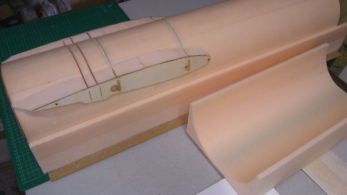
I cut off 36" of pink closed-cell foam from an 8'x4' sheet and sliced it into pieces. I glued together one large and two small pieces and made half-circle templates from plastic laminate.
Using my 38" bow I cut down around and up and produced a very nice cut with a smooth finish. Using another pair of templates with a 6.5" diameter I scooped out the middle of the big piece of foam, leaving the smaller pieces intact with straight sides.
A second piece was cut exactly the same way and the two halves glued together to make a perfect cylinder of foam.
The glue joints became the centreline of my fuselage.
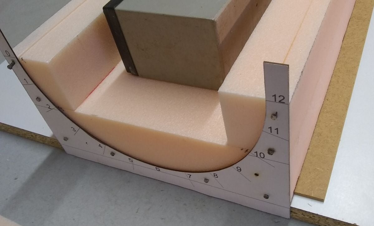
The first semi-circular cut is complete.
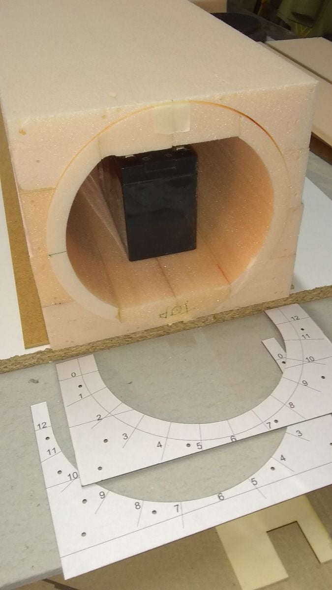
Using the smaller template set i scooped out more foam at the bottom. I made a second half exactly the same and glued them together to make a perfect cylinder.
The cylinder was rotated so that the glue join formed the centreline of the fuselage, top and bottom. The offcuts were put back on.
I laser cut a pair of guides from liteply and cut four slots for the formers where the wing and undercarriage will be mounted. For these small cuts I used my 12" one-handed bow.
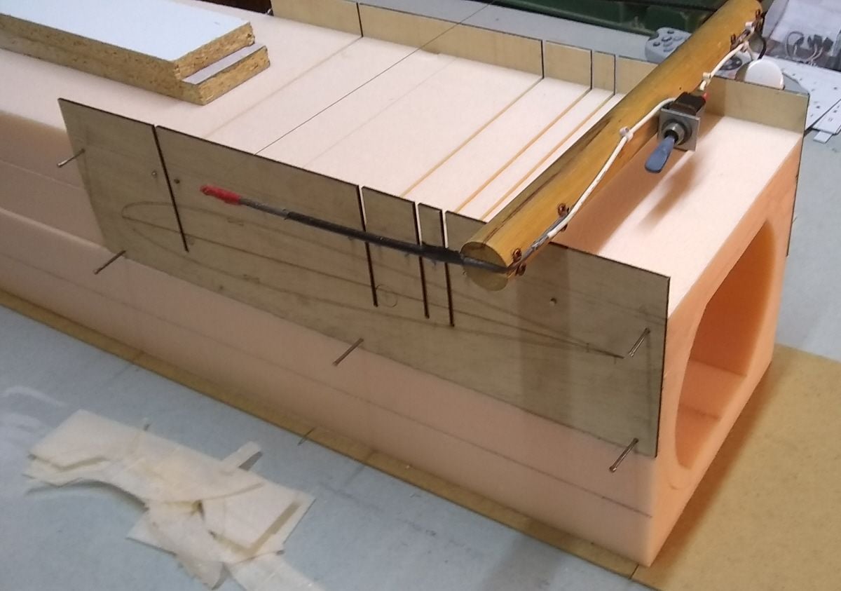
Four accurate slots cut for formers. The root rib shape is etched on the plywood guides.
In my twentieth scale model it needs to be about 34" long and 7.5" diameter.
I cut off 36" of pink closed-cell foam from an 8'x4' sheet and sliced it into pieces. I glued together one large and two small pieces and made half-circle templates from plastic laminate.
Using my 38" bow I cut down around and up and produced a very nice cut with a smooth finish. Using another pair of templates with a 6.5" diameter I scooped out the middle of the big piece of foam, leaving the smaller pieces intact with straight sides.
A second piece was cut exactly the same way and the two halves glued together to make a perfect cylinder of foam.
The glue joints became the centreline of my fuselage.
The first semi-circular cut is complete.
Using the smaller template set i scooped out more foam at the bottom. I made a second half exactly the same and glued them together to make a perfect cylinder.
The cylinder was rotated so that the glue join formed the centreline of the fuselage, top and bottom. The offcuts were put back on.
I laser cut a pair of guides from liteply and cut four slots for the formers where the wing and undercarriage will be mounted. For these small cuts I used my 12" one-handed bow.
Four accurate slots cut for formers. The root rib shape is etched on the plywood guides.
02-19-2021 | 04:24 PM
#17
Unfortunately these have a retract angle of 100 degrees or so. Ideally I'd use 85 degree retracts but 90 might do.
Anyone know how these things work? Is it possible to alter the end stops?
I am reluctant to take them apart without some idea of what I'm doing.
I decided to build with fixed gear. To change I'd need to hack out the mounting plates I've already fitted and make up new mountings.
Anyone know how these things work? Is it possible to alter the end stops?
I am reluctant to take them apart without some idea of what I'm doing.
I decided to build with fixed gear. To change I'd need to hack out the mounting plates I've already fitted and make up new mountings.
Doesn't this just mean they will tuck up a little further into the fuselage?
02-20-2021 | 03:32 AM
#18
Thread Starter
I just measured, and these units have a retract angle of 95 degrees. The legs must hang vertical, so the unit needs to mount with its inboard end canted up at 5 deg, wheres the wing skin (and my mounting beams) cant down at 5 deg.
It is doable, but awkward. I'll stick with fixed gear for now. But I wish I could alter the down stop on the retract to reduce to 90 degrees like the full size aircraft.
Last edited by alasdair; 02-20-2021 at 03:49 AM.
02-20-2021 | 08:51 AM
#19
Thread Starter
Laser cutter was used for fuselage formers, all from 3mm liteply.
F1 is a plywood ring, 7.5" dia outside, 6.5" inside. Four were cut, each with four 1/8" holes for locating pegs.
The A and B are identical and join the nose section to the main centre fuselage.
The C and D join the rear fuselage to the front, so F1D on the built up rear section has 1/16" shaved off the outer edge for the balsa sheeting and is spit into two parts, right and left.

Also cut were the engine mount plate and root ribs.
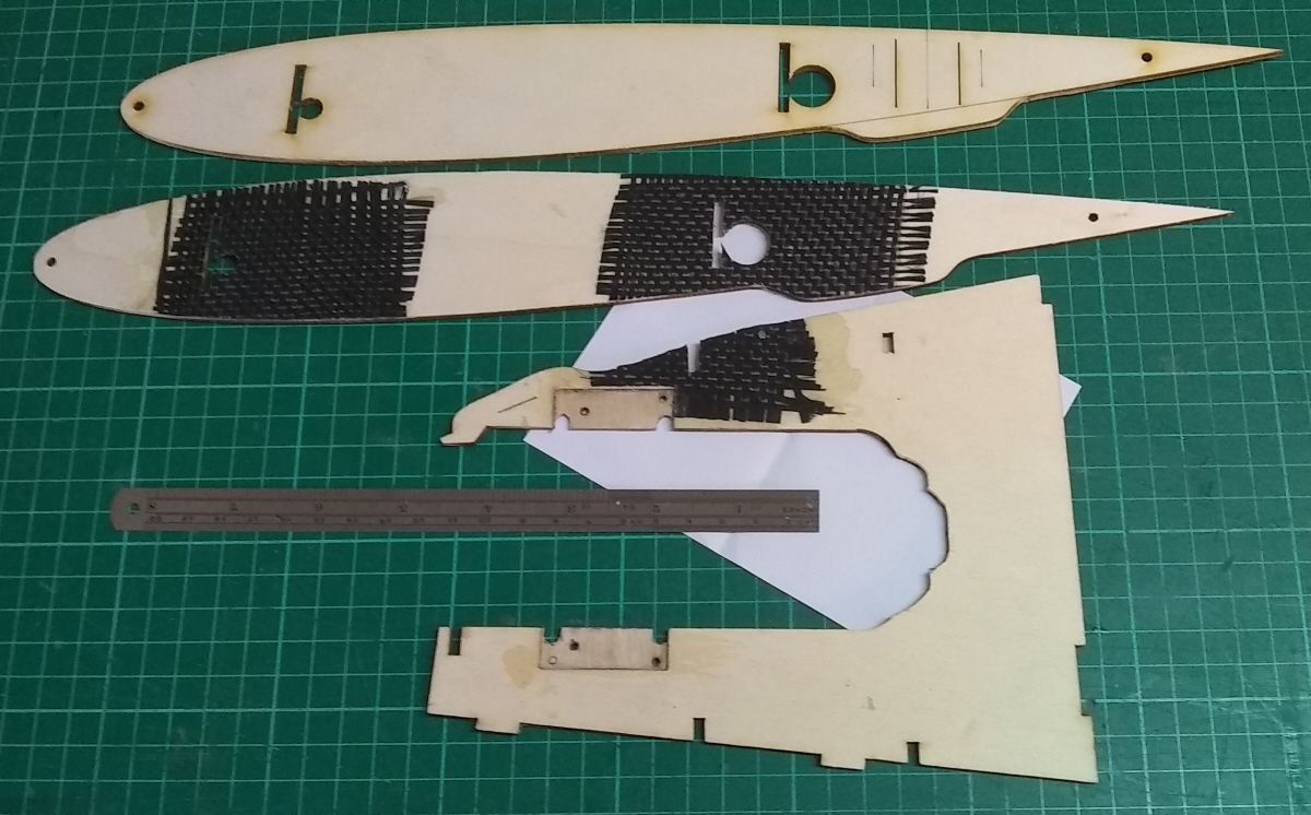
The root ribs are reinforced with carbon cloth on the inside around where the wing supports and undercarriage supports fit.
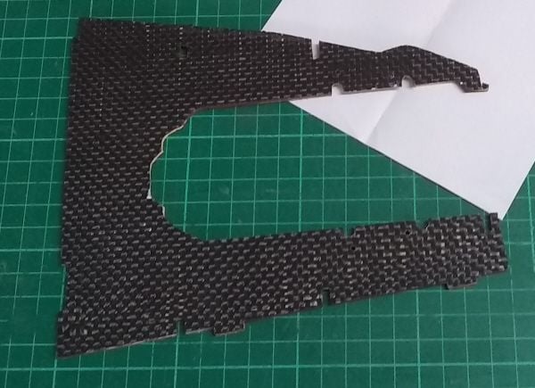
The engine mount has carbon cloth all over on its stbd side
These four formers slide into the slots already cut in the fuselage. All are reinforced with carbon cloth on one side, applied with laminating epoxy.

The left two support the main undercarriage, the right two support the root ribs and the wing joining tubes.
F1 is a plywood ring, 7.5" dia outside, 6.5" inside. Four were cut, each with four 1/8" holes for locating pegs.
The A and B are identical and join the nose section to the main centre fuselage.
The C and D join the rear fuselage to the front, so F1D on the built up rear section has 1/16" shaved off the outer edge for the balsa sheeting and is spit into two parts, right and left.
Also cut were the engine mount plate and root ribs.
The root ribs are reinforced with carbon cloth on the inside around where the wing supports and undercarriage supports fit.
The engine mount has carbon cloth all over on its stbd side
These four formers slide into the slots already cut in the fuselage. All are reinforced with carbon cloth on one side, applied with laminating epoxy.
The left two support the main undercarriage, the right two support the root ribs and the wing joining tubes.
 02-21-2021 | 11:39 AM
#21
Thread Starter
A bit more work to show on the centre fuselage.
The extra 2 inches of cylinder were cut off and plywood former F1A was glued on.
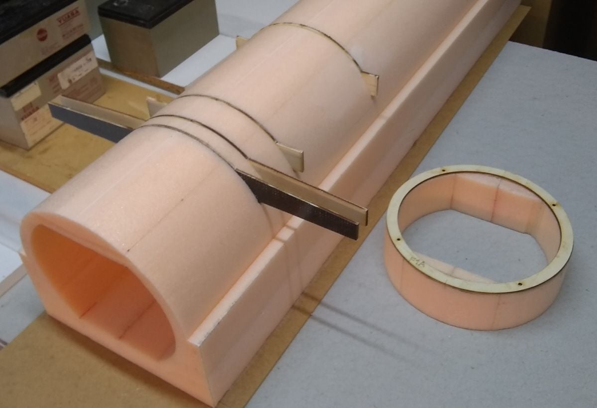
A trial fitting of the formers before glassing the cylinder. That extra 2" piece of foam cylinder will make the basis for the nose section.
Both ends of the centre fuselage had their plywood formers glued on also, and then the whole thing was covered with 50g glasscloth in one piece, applied with epoxy resin scraped on with a credit card.
The formers were slid into their slots in the foam and glued in place. Some balsa triangle reinforced the join where the former edge meets the flat bit of foam at the top.
The root ribs in the middle photo of post #19 were glued to some scrap offcuts of foam and shaped to fit onto the cylinder, with the ribs located on the ends of the wing mounting formers. It was all glued together, including the sleeves for fore and aft wing tubes which were also epoxied to the formers.
The root ribs are at +3.6 degrees to the fuselage
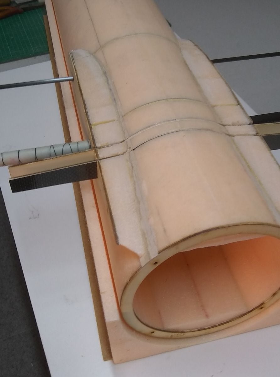
Because the glasscloth covering was cut to insert the formers, a glass patch was epoxied over the cuts to restore strength.
The extra 2 inches of cylinder were cut off and plywood former F1A was glued on.
A trial fitting of the formers before glassing the cylinder. That extra 2" piece of foam cylinder will make the basis for the nose section.
Both ends of the centre fuselage had their plywood formers glued on also, and then the whole thing was covered with 50g glasscloth in one piece, applied with epoxy resin scraped on with a credit card.
The formers were slid into their slots in the foam and glued in place. Some balsa triangle reinforced the join where the former edge meets the flat bit of foam at the top.
The root ribs in the middle photo of post #19 were glued to some scrap offcuts of foam and shaped to fit onto the cylinder, with the ribs located on the ends of the wing mounting formers. It was all glued together, including the sleeves for fore and aft wing tubes which were also epoxied to the formers.
The root ribs are at +3.6 degrees to the fuselage
Because the glasscloth covering was cut to insert the formers, a glass patch was epoxied over the cuts to restore strength.
02-22-2021 | 06:33 AM
#23
Thread Starter
Next job was to make the nose section.
Three thicknesses of 2" foam were cut on the old Dremel scroll saw to the side profile. The centre one had much of the inside hollowed out using the saw. The two on either side had some foam removed using the hot wand, and then the three pieces were glued together. A bit of the curved scrap that had been removed by the hot wire was added to make up the extra thickness.
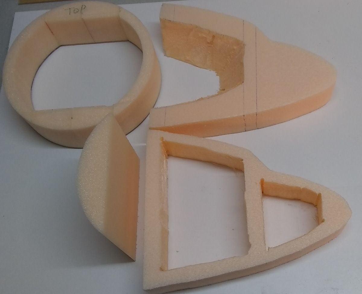
Some of the pieces.
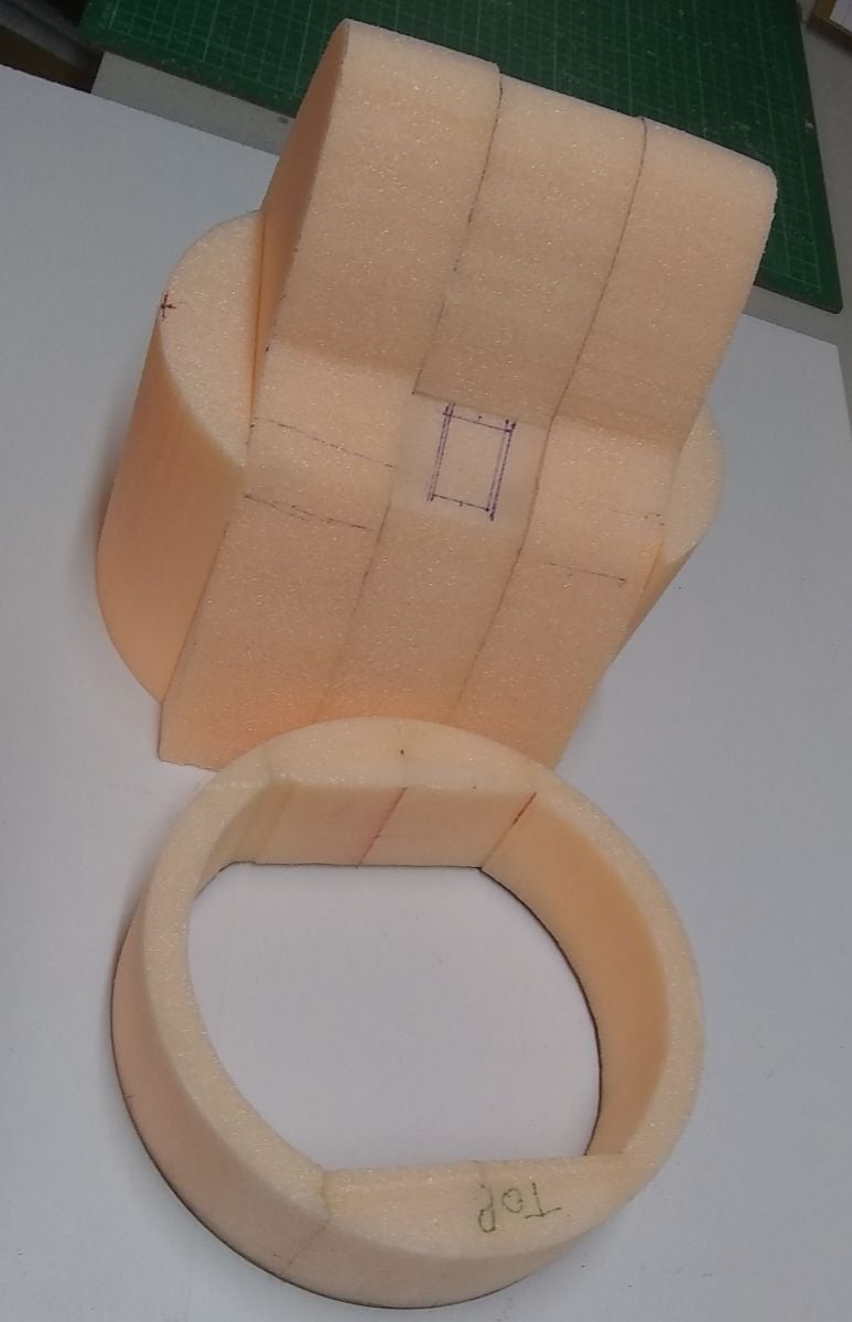
All the pieces glued together ready to add to the foam ring.
After gluing all these pieces onto the foam ring, with its plywood ring former F1A, the whole thing was carved to shape (messy).
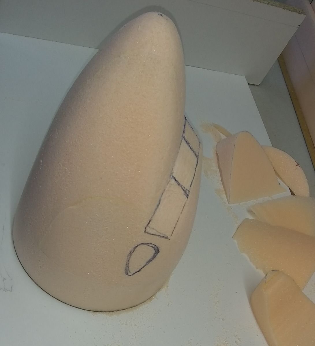
As part of the carving process the flat spots for the cockpit windows were made.
The whole thing (except for windows) had its outside covered with 50g glasscloth and epoxy resin (messy again).
Three thicknesses of 2" foam were cut on the old Dremel scroll saw to the side profile. The centre one had much of the inside hollowed out using the saw. The two on either side had some foam removed using the hot wand, and then the three pieces were glued together. A bit of the curved scrap that had been removed by the hot wire was added to make up the extra thickness.
Some of the pieces.
All the pieces glued together ready to add to the foam ring.
After gluing all these pieces onto the foam ring, with its plywood ring former F1A, the whole thing was carved to shape (messy).
As part of the carving process the flat spots for the cockpit windows were made.
The whole thing (except for windows) had its outside covered with 50g glasscloth and epoxy resin (messy again).
02-23-2021 | 09:08 AM
#24
Thread Starter
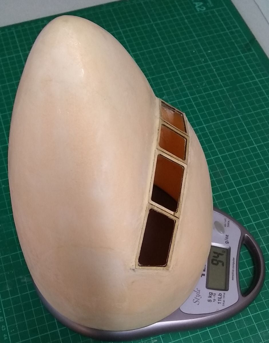
A little more to add about the front end of my mini Trident.
I cut window frames from 1/16" birch ply and epoxied them in place (just the front 5 cockpit windows, the others will be painted on or stuck on).
Then I used my hot wand to cut away all the foam that I could reach in through the windows, and I cut away some of the foam inside the cockpit, from behind.
I didn't measure the windows when I visited FB at Duxford. I did it by eye from the photos and may have made them a little too large.
So what if it's a caricature of a Trident? The model is only a proof of concept.
The plywood window frames made cutting out the foam easy.
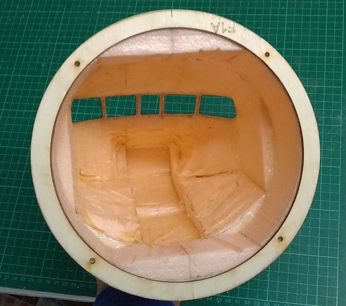
I also cut away some foam inside, and a crude slot where the floor would be.
I know this is just a proof of concept model but I couldn't resist making a crude cockpit interior, just a floor and backwall from cardboard, two chairs and one pilot. (the copilot, the captain's gone to chat up the stewardess in the galley and the third man, his seat and his panel are too far back to see anyway.)
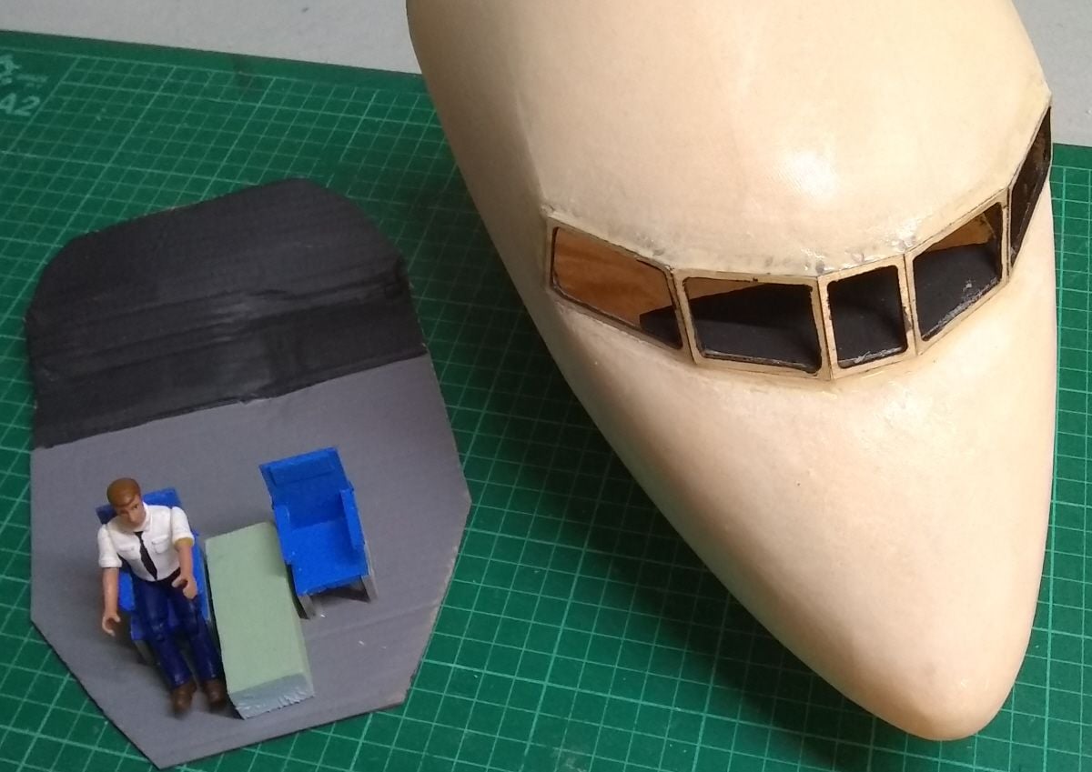
Minimalist to say the least.
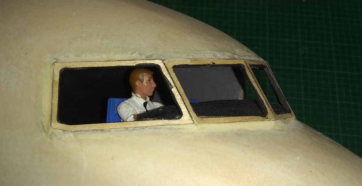
But from here he looks OK.
I cut window frames from 1/16" birch ply and epoxied them in place (just the front 5 cockpit windows, the others will be painted on or stuck on).
Then I used my hot wand to cut away all the foam that I could reach in through the windows, and I cut away some of the foam inside the cockpit, from behind.
I didn't measure the windows when I visited FB at Duxford. I did it by eye from the photos and may have made them a little too large.
So what if it's a caricature of a Trident? The model is only a proof of concept.
The plywood window frames made cutting out the foam easy.
I also cut away some foam inside, and a crude slot where the floor would be.
I know this is just a proof of concept model but I couldn't resist making a crude cockpit interior, just a floor and backwall from cardboard, two chairs and one pilot. (the copilot, the captain's gone to chat up the stewardess in the galley and the third man, his seat and his panel are too far back to see anyway.)
Minimalist to say the least.
But from here he looks OK.
Last edited by alasdair; 02-23-2021 at 09:11 AM.

