


Saab 37 Viggen - Custom Wings 1:9 scale turbine
 02-26-2022, 06:35 PM
#26

Thread Starter
Ed from RcCrafters developed an initial design using a custom side mounted actuator. He sent me the design for me to see if it fitted.

RcCrafters - nose unit. Note the oleo support is on the starboard side on the Viggen.
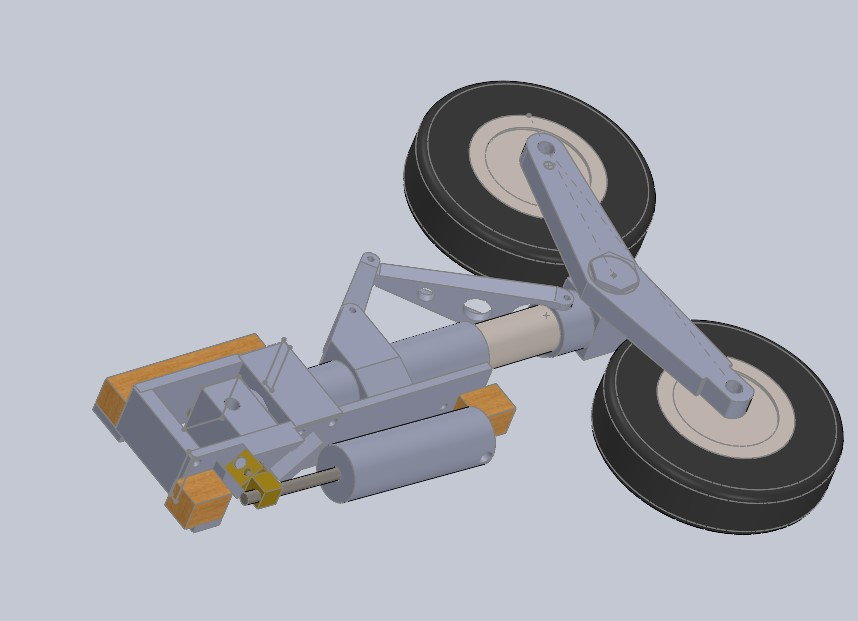
RcCrafters - Left main unit initial design (retracted). Note the oleo support points forward, actuator is on the aft side.
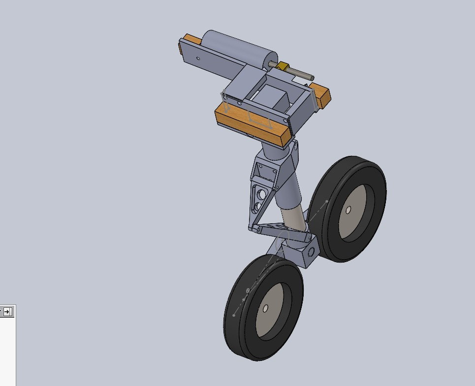
RcCrafters - Left main unit initial design (extended). Note the oleo support points forward, actuator is on the aft side.
RcCrafters - nose unit. Note the oleo support is on the starboard side on the Viggen.
RcCrafters - Left main unit initial design (retracted). Note the oleo support points forward, actuator is on the aft side.
RcCrafters - Left main unit initial design (extended). Note the oleo support points forward, actuator is on the aft side.
Last edited by rustyives; 02-26-2022 at 10:14 PM. Reason: typo
 02-26-2022, 06:49 PM
#27
Thread Starter
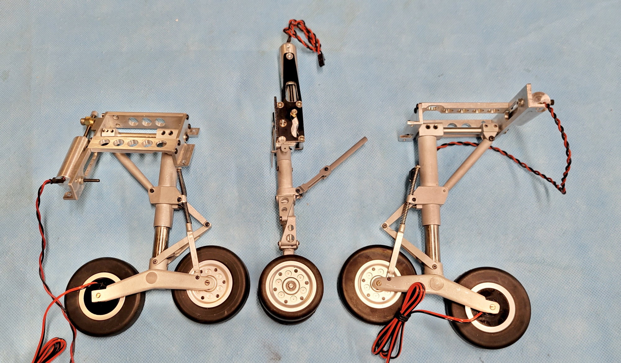
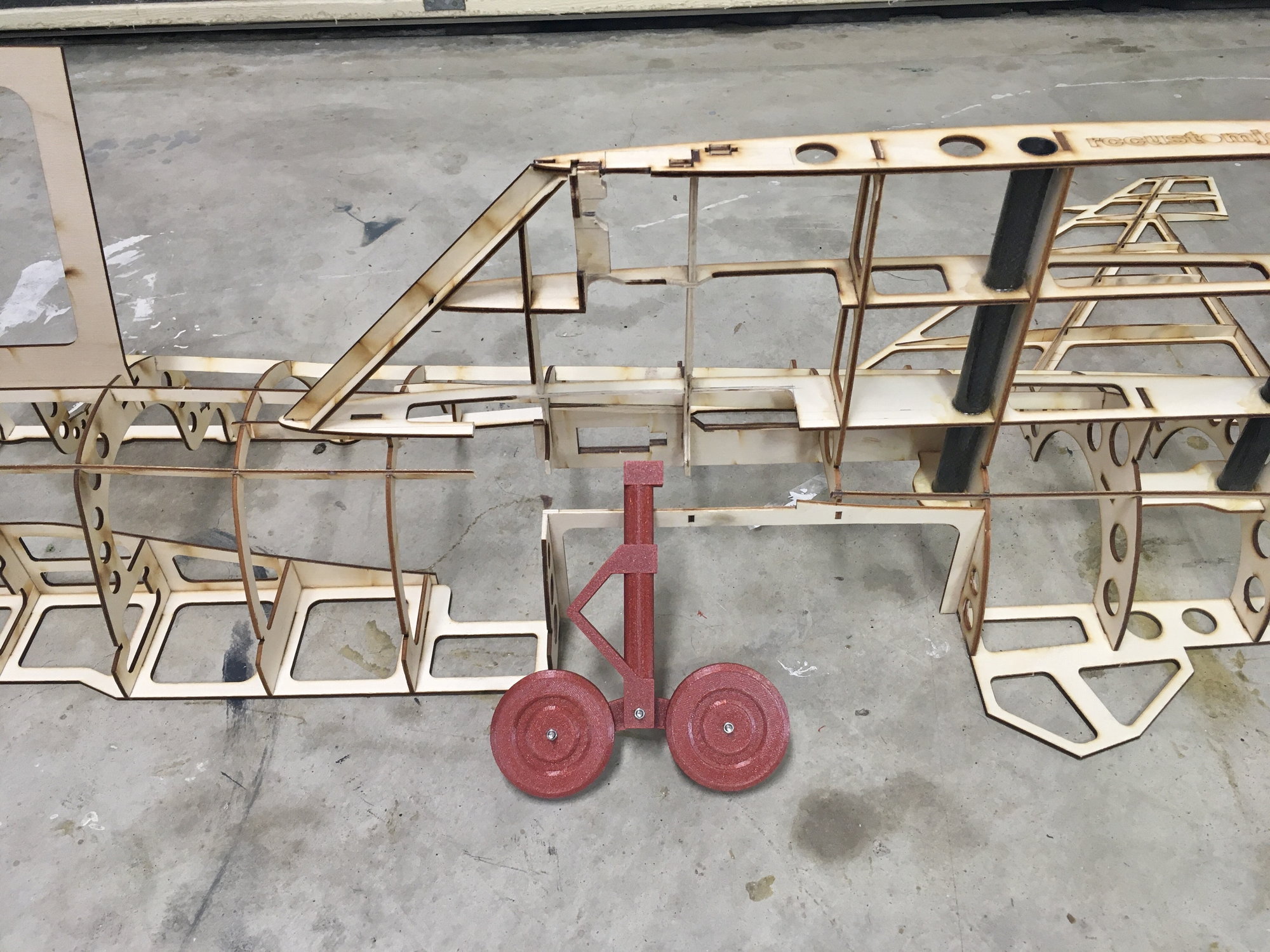
I used Ed�s initial design and 3D printed a set to try it out (much easier than Papier-m�ch�). The first question related to the strut lengths, to make sure the mains and nose lined up correctly so that the plane sits level on the ground. The Mains use a 65mm wheel and the Nose twin 50mm units with the final products from JP Hobby.
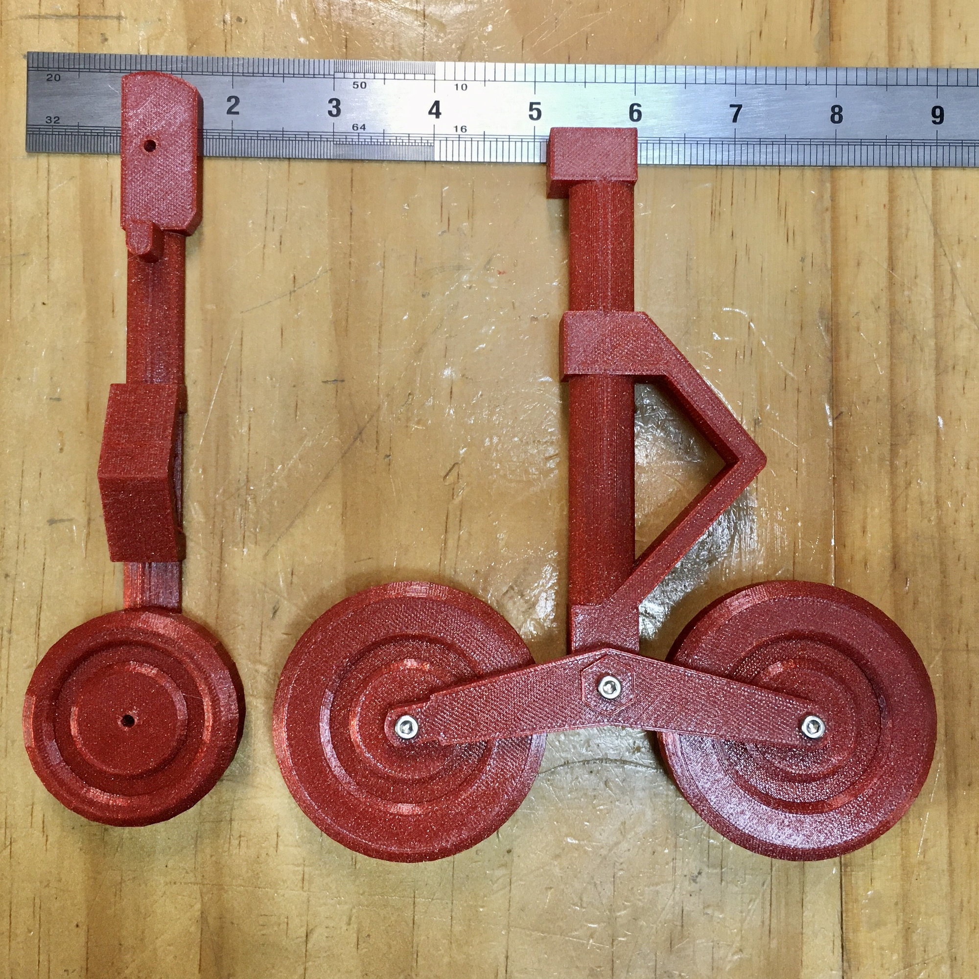
3D printed representations of RCcrafters inital design
Layout of the Mains and Nose units to check the relative strut lengths. All good.
3D printed representations of RCcrafters inital design
Layout of the Mains and Nose units to check the relative strut lengths. All good.
02-26-2022, 07:08 PM
#28
Thread Starter
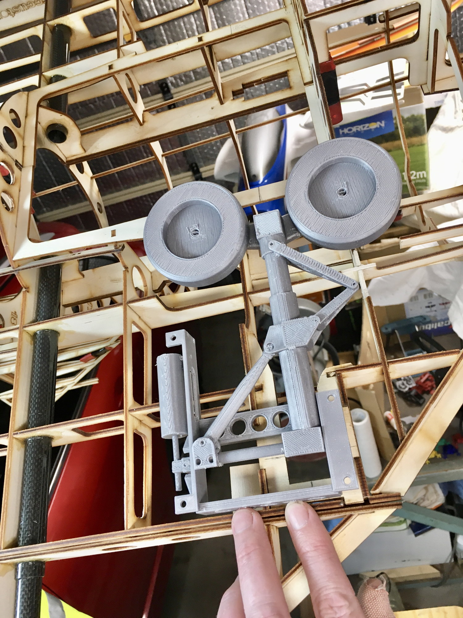
When putting the Mains up against the constructed kit, it shows the design did not accommodate the forward wheel of the mains when retracted into the fuselage. ** Custom Wings � recommend you move Frame 14 design forward to 13, and copy/past Frame 15 design to 14 (will result in extension of EDF engine access hatch by one frame too) **.
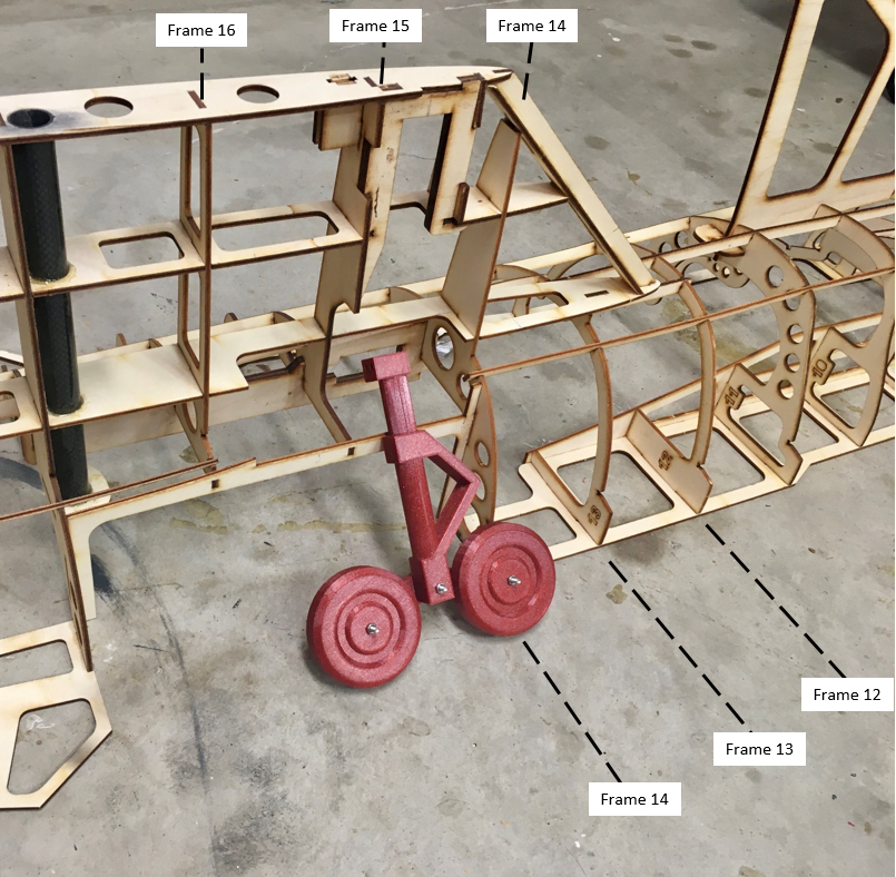
Issue with Mains retracting into Frame 14
Clash with Frame 14 - Some work with the Dremel and some custom framing & formers are required....
Issue with Mains retracting into Frame 14
Clash with Frame 14 - Some work with the Dremel and some custom framing & formers are required....
02-26-2022, 07:22 PM
#29
Thread Starter
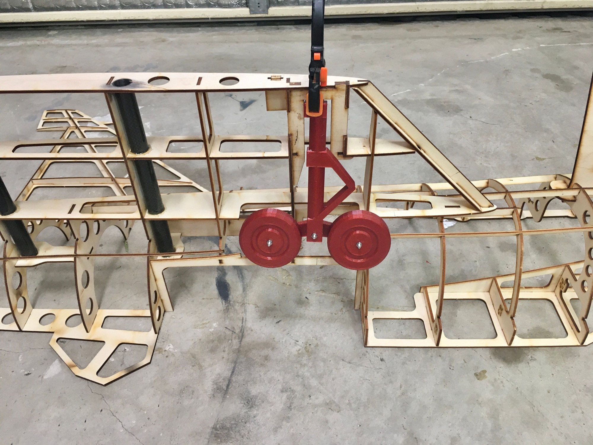
However, there is plenty of space behind the Mains in the wing area, and I just happened to come across this video showing this superb set of mains for a 1:5 scale build.
So why not incorporate a back brace into this set, there is plenty of room in the wing and it should provide some really good support to the mains when loaded aft on landing.
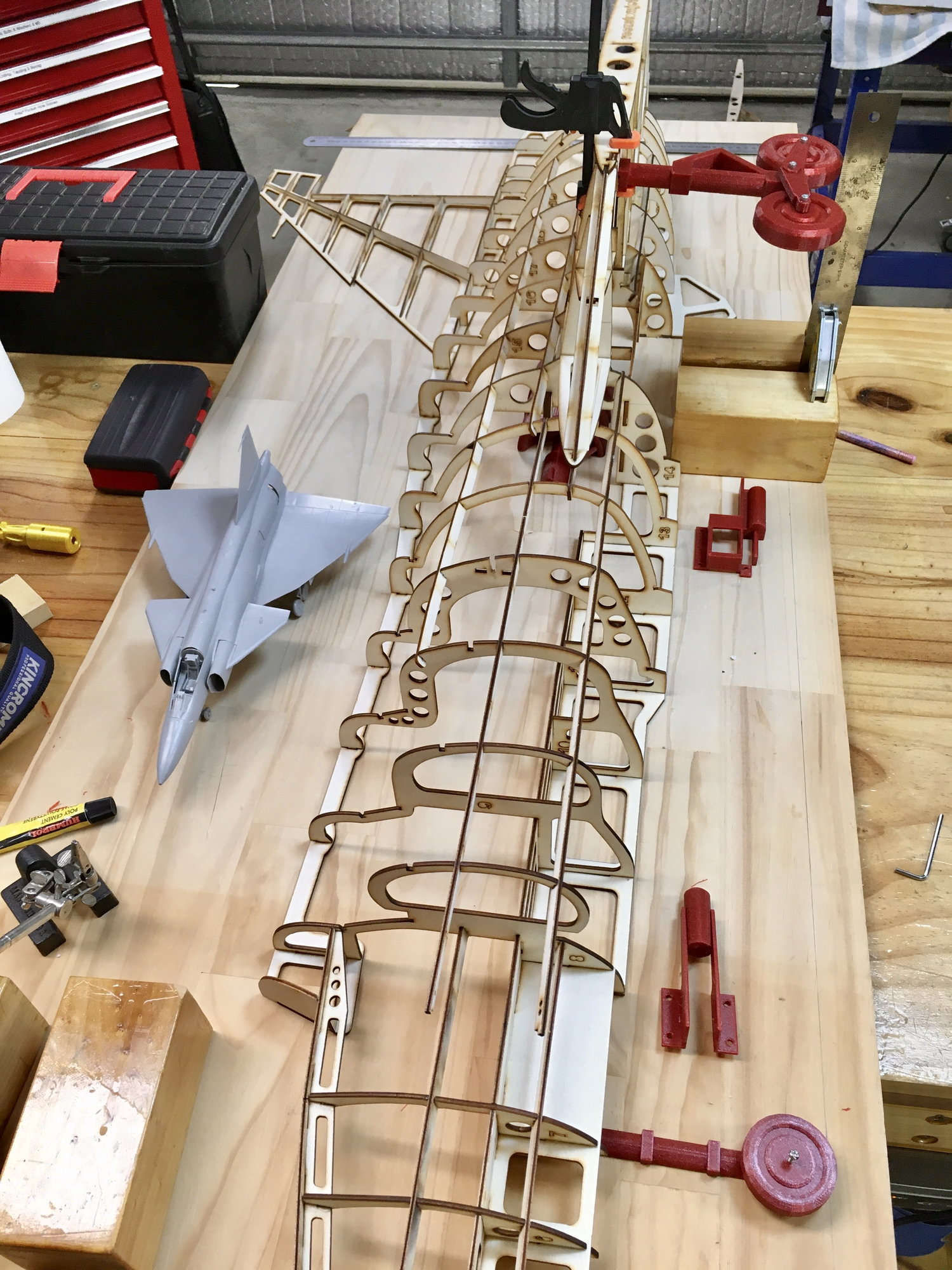
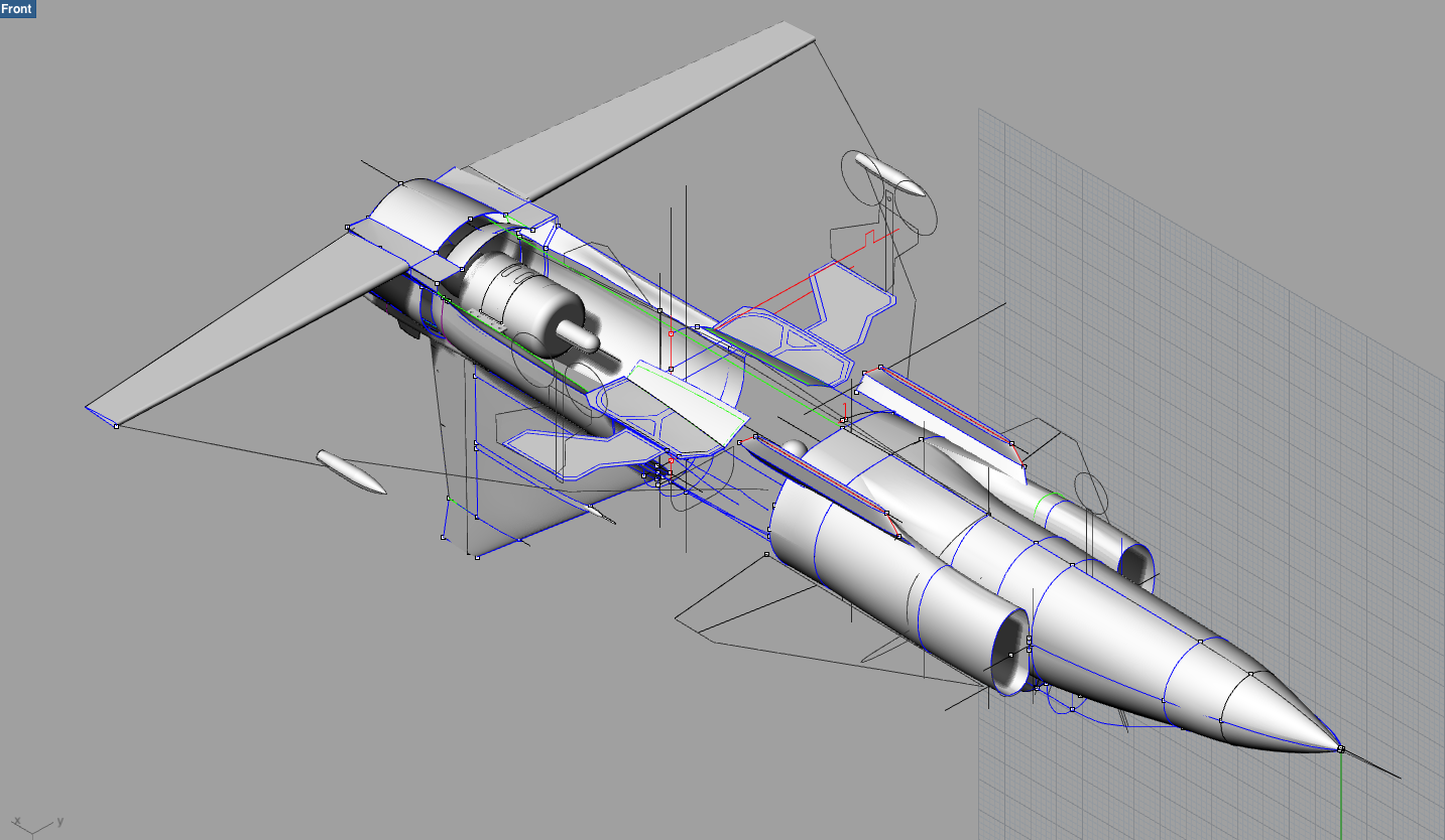
Frame 14 cutaway to fit in the Mains. That's a K-85G2 represented in the background for turbine positioning setup.
So why not incorporate a back brace into this set, there is plenty of room in the wing and it should provide some really good support to the mains when loaded aft on landing.
Frame 14 cutaway to fit in the Mains. That's a K-85G2 represented in the background for turbine positioning setup.
02-26-2022, 07:30 PM
#30
Thread Starter
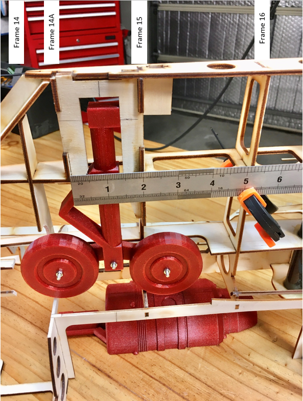
Ed from RcCrafters was very accommodating with the addition of an aft brace. He sent me the STL files of his CAD design and I simply threw them on the printer (with supports) for a PLA print. Not particularly suited to a 3D print, but really handy to work out what fits.
Quick 3D print from RcCrafters STL file of Ed's CAD design with the aft brace in place
Fits fine, just some minor optimisations before the final design
Quick 3D print from RcCrafters STL file of Ed's CAD design with the aft brace in place
Fits fine, just some minor optimisations before the final design
Last edited by rustyives; 02-26-2022 at 10:14 PM. Reason: typo
02-26-2022, 09:23 PM
#31
Thread Starter
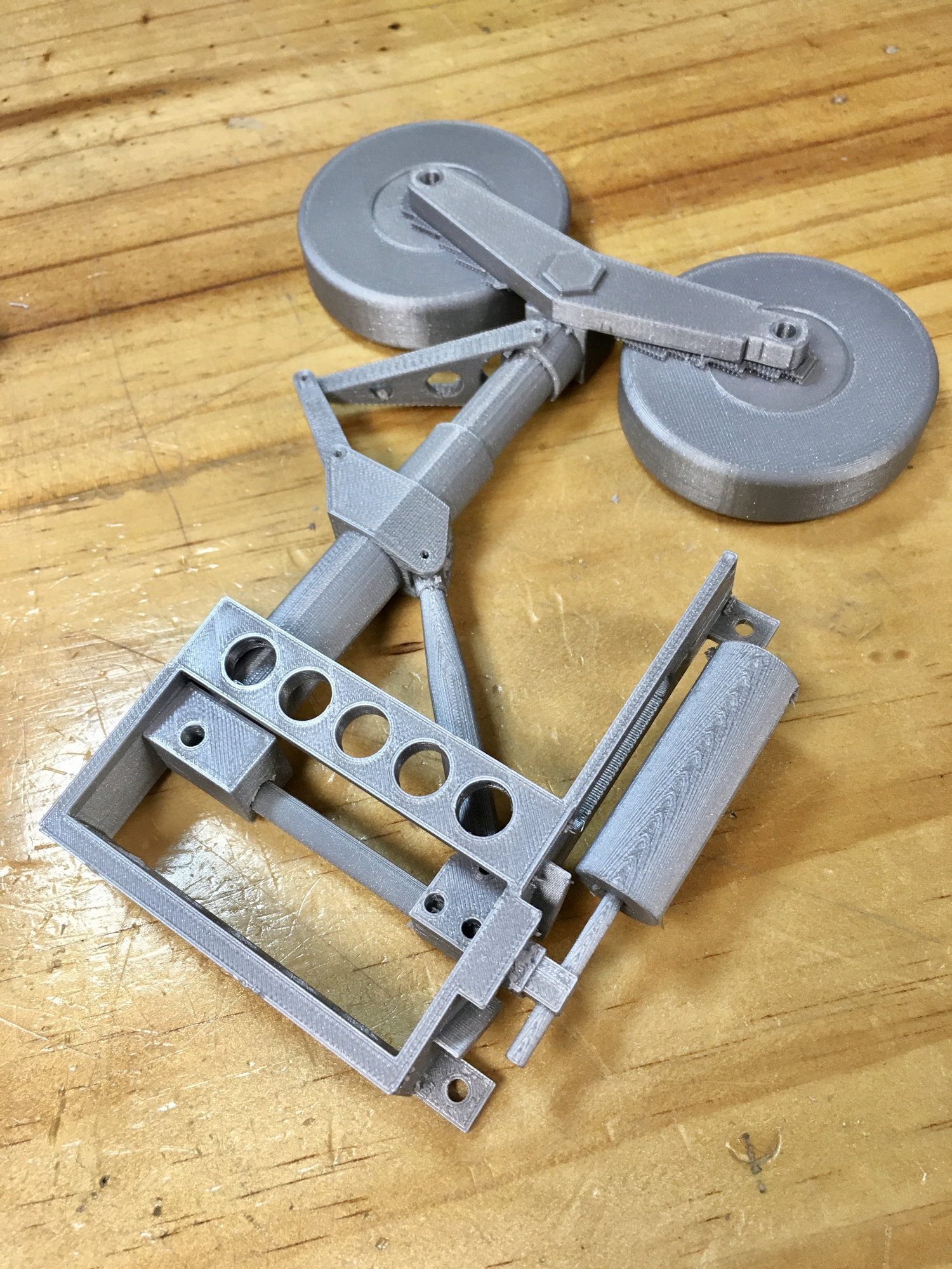
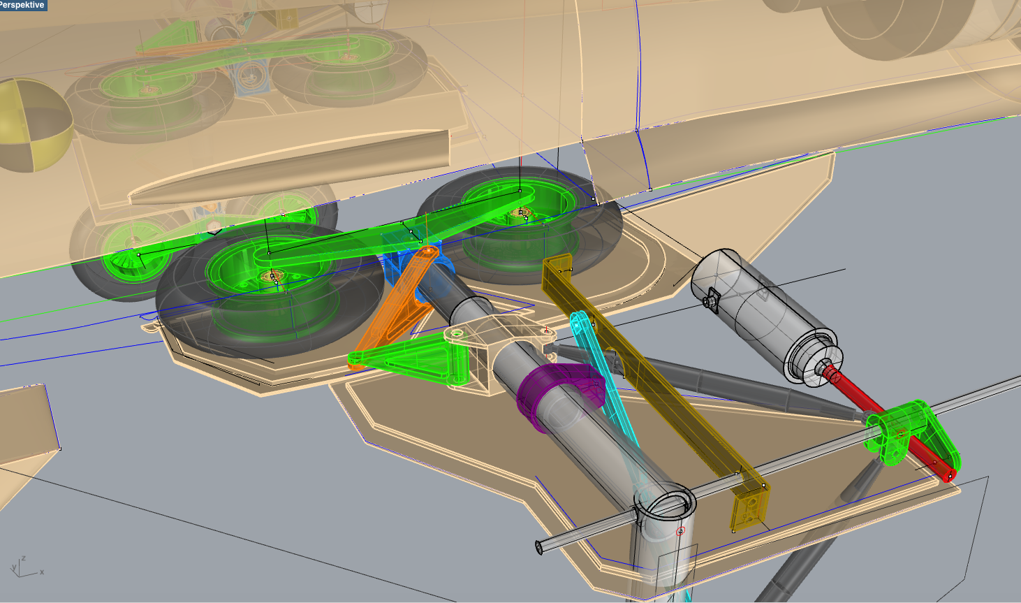
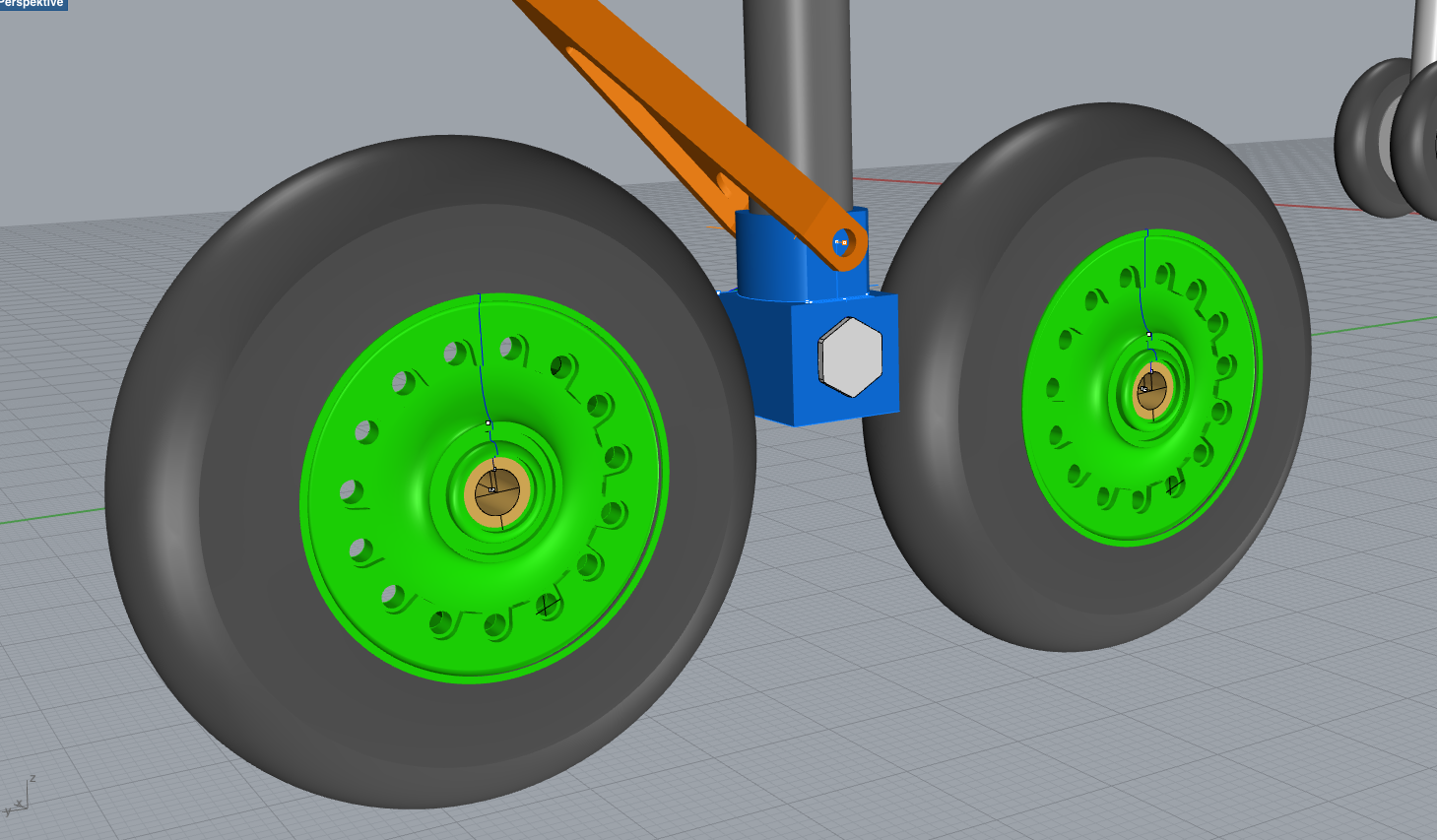
Ed finalised the design and started the build. He also added an �Alignment Link� so that the undercarriage tandem wheel strut can self-align when not under load. This is both scale (per the photo) below and very handy to align the tandem wheel strut prior to retraction.
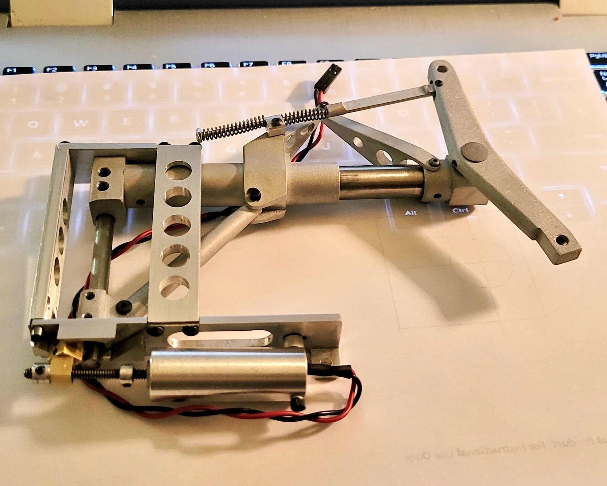
Ed sending me teaser shots of the mains assembled prior to attachment of the wheels. Note the alignment link has double spring design for easy centering adjustment.
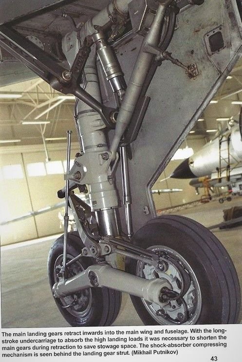
Photo from the internet showing the layout of the Mains. Note the alignment link on the front which has been replicated in the RCcrafter's design.
Ed sending me teaser shots of the mains assembled prior to attachment of the wheels. Note the alignment link has double spring design for easy centering adjustment.
Photo from the internet showing the layout of the Mains. Note the alignment link on the front which has been replicated in the RCcrafter's design.
02-26-2022, 09:31 PM
#32
Thread Starter
Ed�s completed design built ready to send, superb bit of kit! Ed says he made enough parts for 5 sets, so if anyone is interested in getting a set for this kit, get in fast with https://rccrafters.com/#
02-26-2022, 09:50 PM
#33
Thread Starter
Because of the design of Frame 14 mentioned earlier, together with the addition of the Aft Brace to the undercarriage, the Dremel had a bit of a workout. The photos below ONLY have material removed from the original Custom Wings design, I have not added any structure at this stage. It’s purely to show the modification I did to the kit to fit it in.
There have been no issues with the RcCrafters undercarriage, it fits in the wing fine. All this rework is around accommodating the kit design around this undercarriage.
The kit structure I removed in order to fit in the undercarriage. 3D printed Mains included for reference aligned with their mounting location.
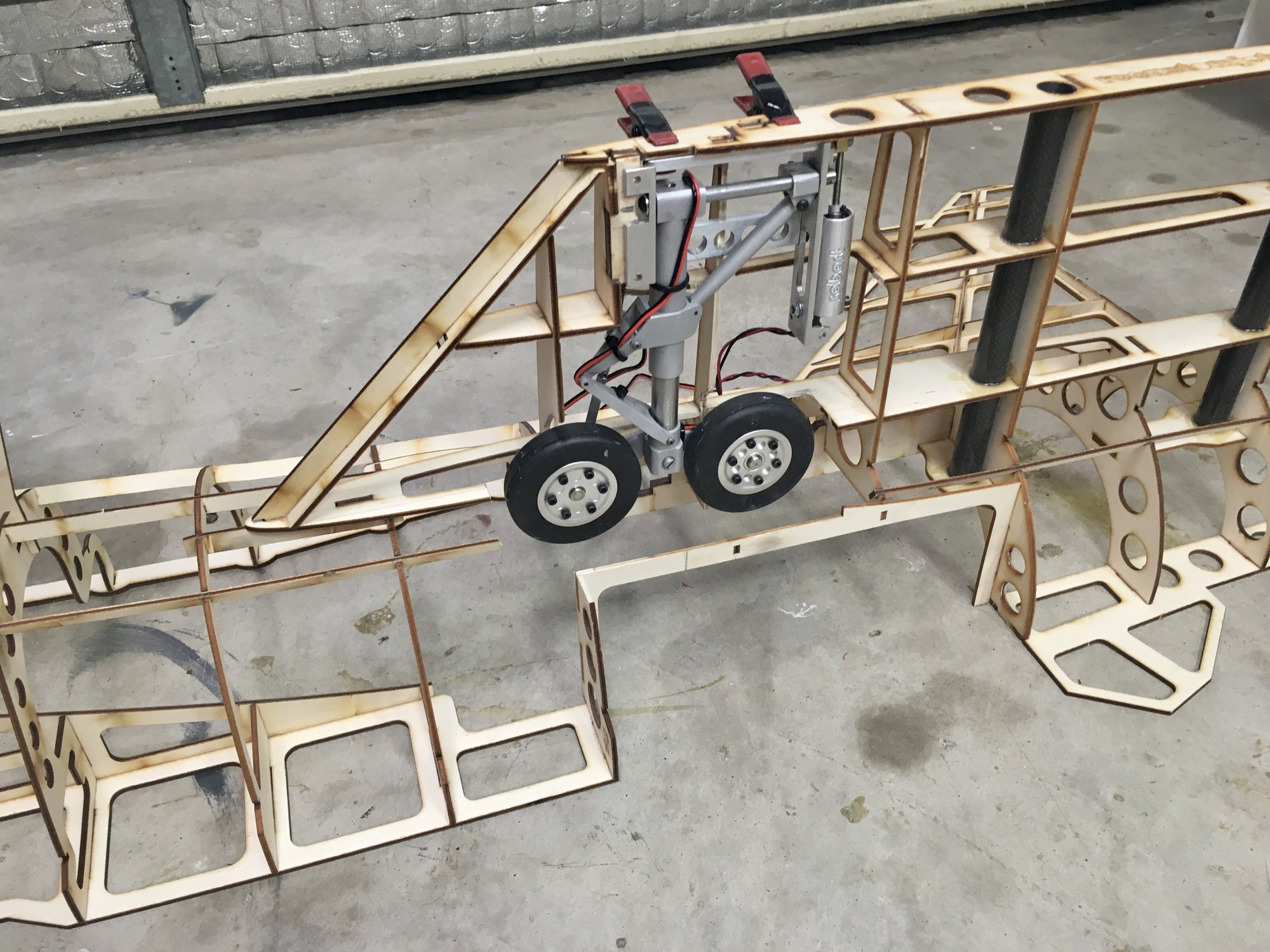
Installed RcCrafter's Viggen undercarriage. Now to build in the mounting and support structure.
There have been no issues with the RcCrafters undercarriage, it fits in the wing fine. All this rework is around accommodating the kit design around this undercarriage.
The kit structure I removed in order to fit in the undercarriage. 3D printed Mains included for reference aligned with their mounting location.
Installed RcCrafter's Viggen undercarriage. Now to build in the mounting and support structure.
Last edited by rustyives; 02-26-2022 at 10:13 PM. Reason: typo
02-26-2022, 09:54 PM
#34
Thread Starter
This thread is now up to me in real time. My next stage is to build in the support structure to the undercarriage and get it working. Hopefully so I can clip the two sides of the airframe together and push it around the yard! Will keep you all posted with how I go� including the nose retract
04-11-2022, 07:49 AM
#35

Hello,
how heavy is the nose gear and main landing gear? What is the cost of the complete landing gear from RCCrafter?
I am planning to build a Saab Viggen by Einar Johnsson 1/8 . Unfortunately the kit is not complete and the landing gear would have to be made by myself.
Regards
Frank
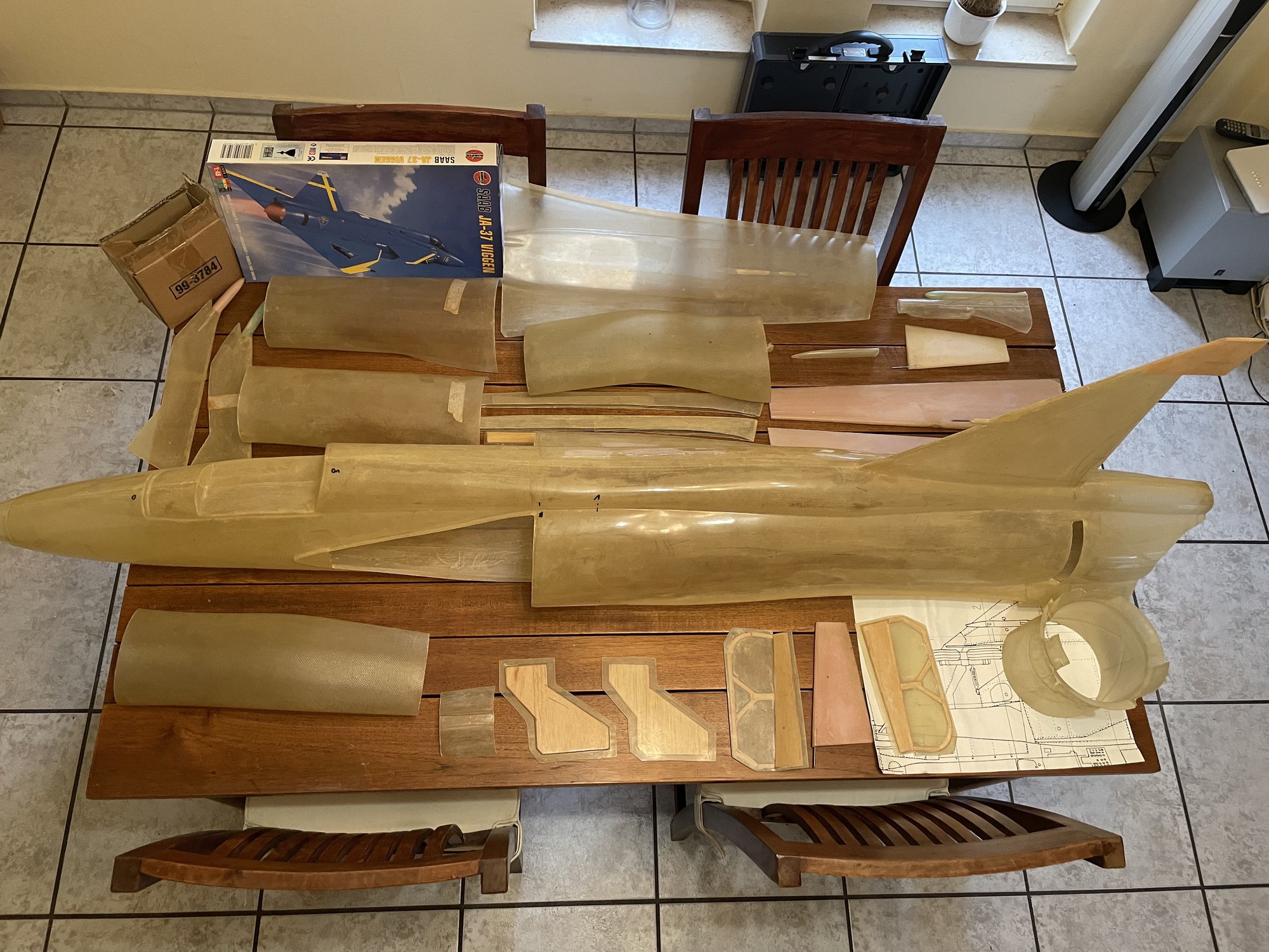
Einar Johnsson Kit 1/8
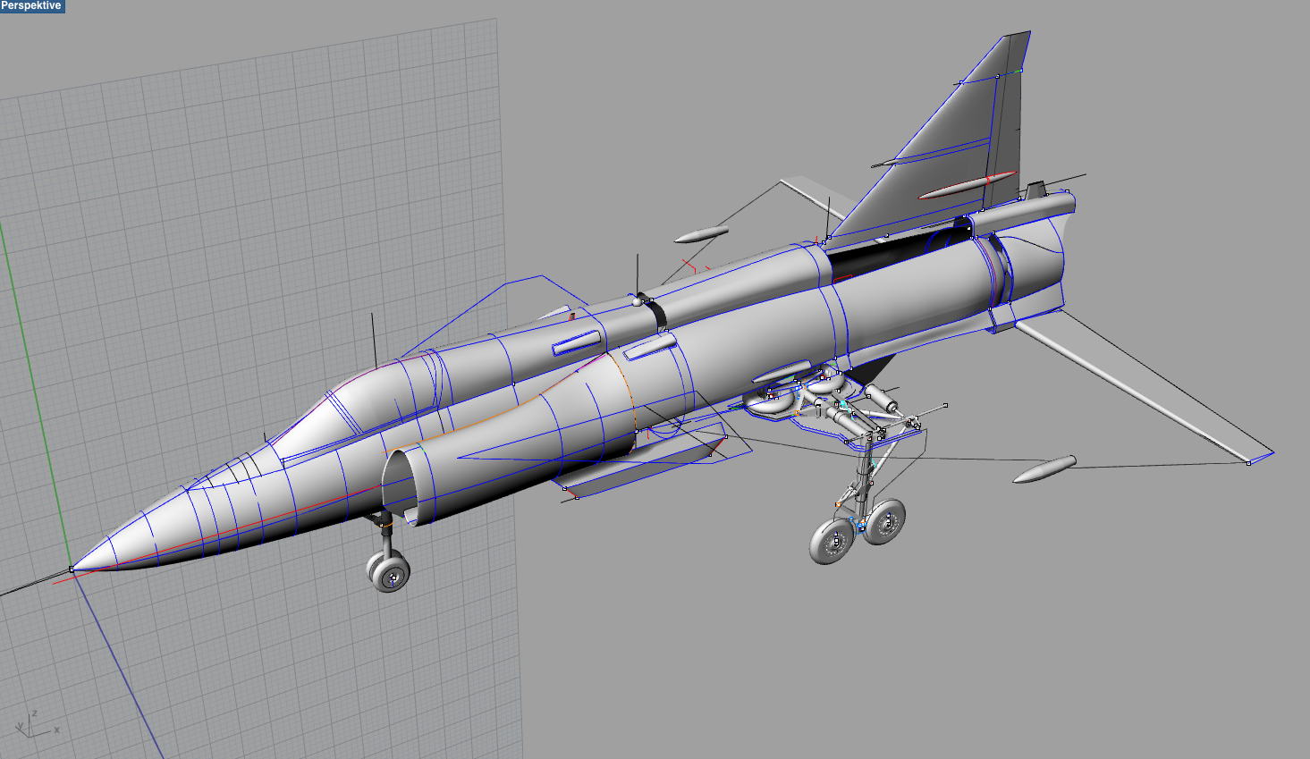
3D Model
Main gear with JP 200
Main wheels x 4

nose gear
BF Turbines - B140F
04-11-2022, 09:46 PM
#36
Thread Starter
Hi Frank. The nose gear unit is 236g (123g without the retract unit), and the mains are 390g each all up. The complete set at 1:9 scale including custom undercarriage, Robart retract units, Robart retract controller, 6 x JP Hobby wheels, JP Hobby brake set (excluding shipping) was around the USD 1,500 mark to give an indication. Obviously costs are changing all the time at the moment, but it should give you a ball park number.
Nice work with your undercarriage design, they look really good, and I like the CAD work. That Einar Johnsson kit looks flash. Does it come with the undercarriage doors too? - I'm trying to work out the size of those at the moment from 3-view drawings as the Custom Wings kit doesn't provide any plans or reference material unfortunately.
Nice work with your undercarriage design, they look really good, and I like the CAD work. That Einar Johnsson kit looks flash. Does it come with the undercarriage doors too? - I'm trying to work out the size of those at the moment from 3-view drawings as the Custom Wings kit doesn't provide any plans or reference material unfortunately.
04-12-2022, 12:40 PM
#37
Thank you for the weight data. The height from the main landing gear of 30mm should not be exceeded.
The landing gear doors included in the kit can be seen in the first picture. There are several pictures of the landing gear doors. I used the 2D drawing as a guide....see pictures below.
I have deposited two landing gear doors on the website of Thingiverse.
https://www.thingiverse.com/thing:5351398
Regards Frank
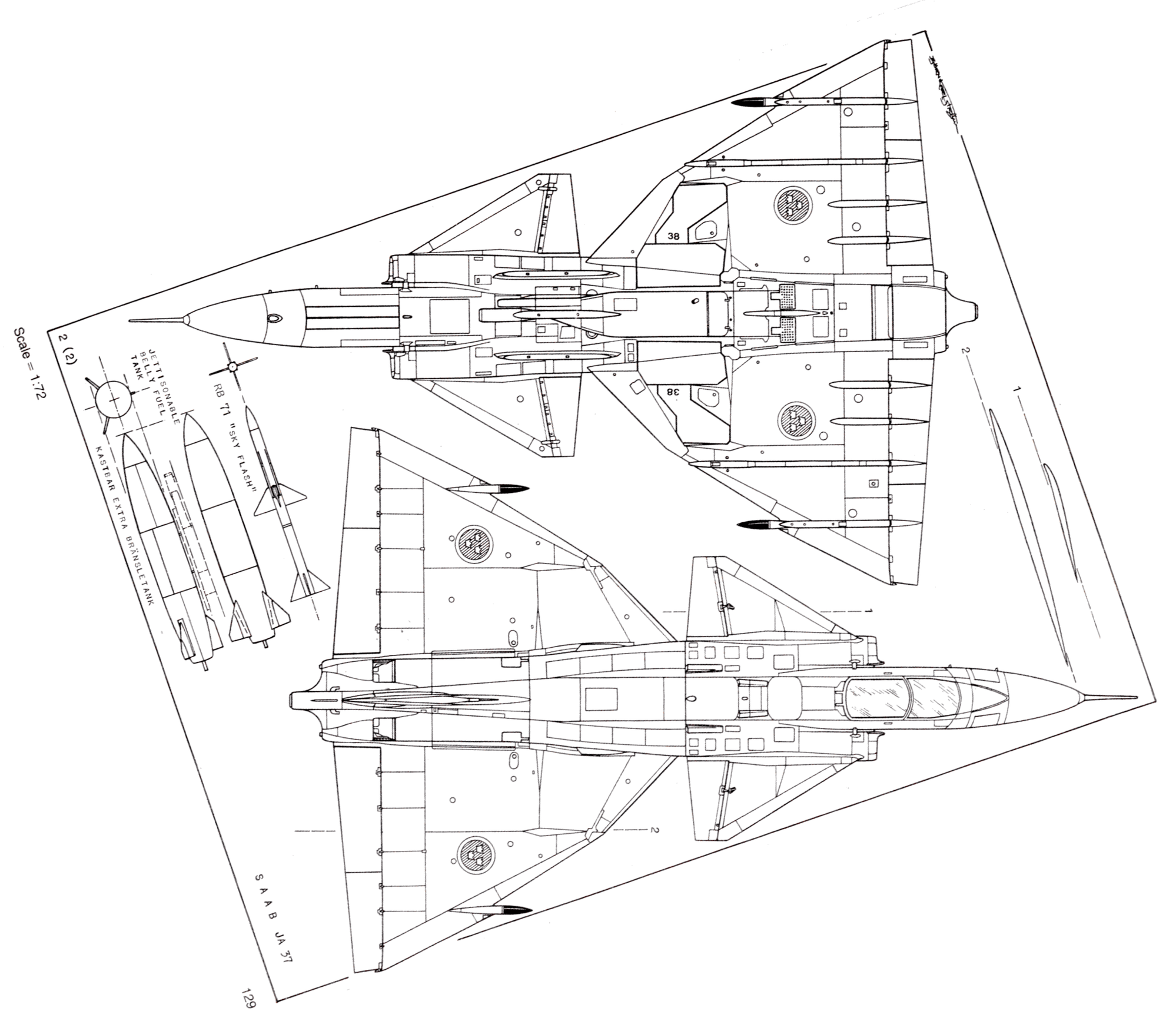
The following users liked this post:
rustyives (04-13-2022)
08-17-2022, 01:12 AM
#39
Thread Starter
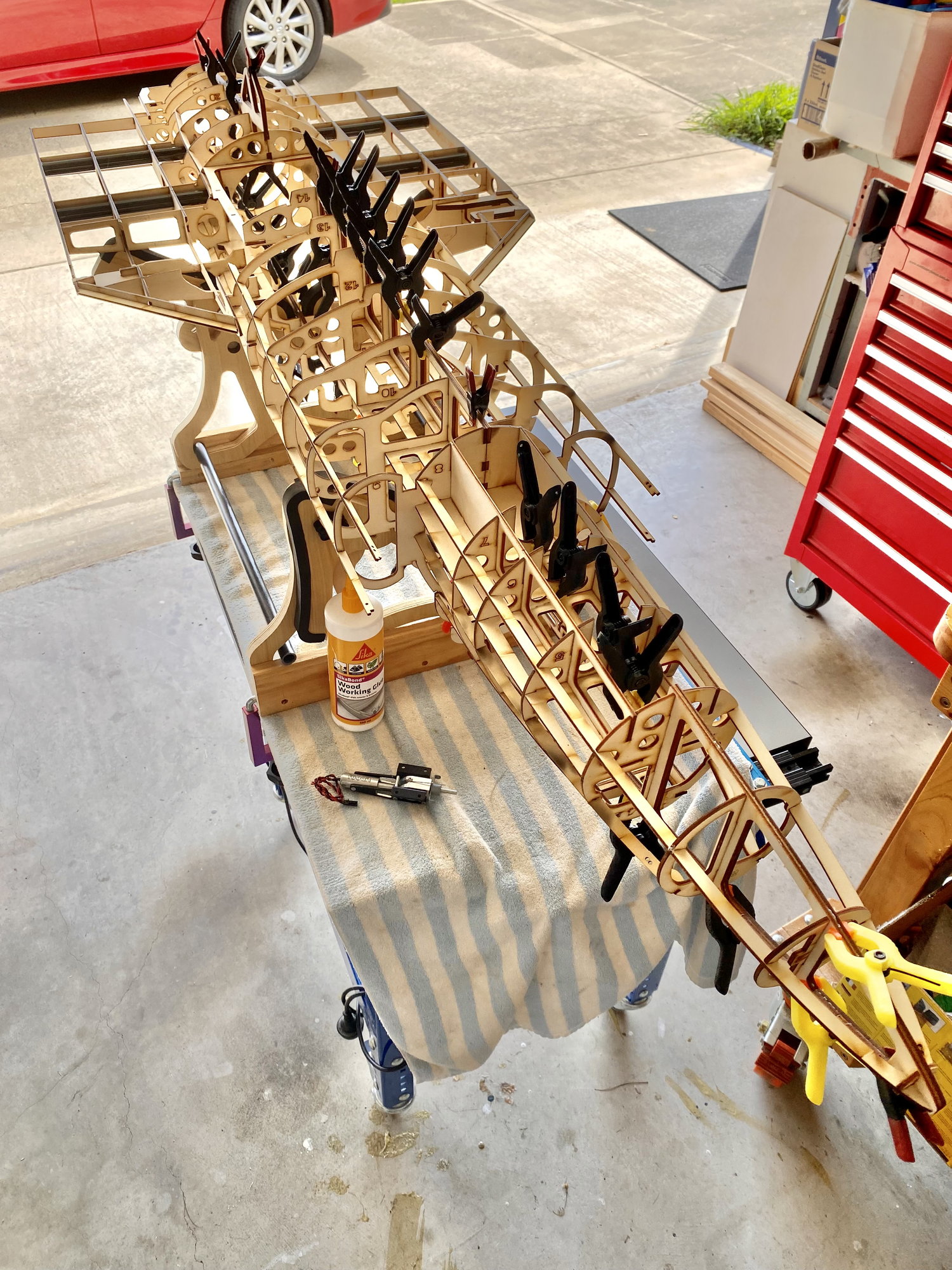
Ok, so I may have had the kit hanging from my ceiling while I was doing other projects and thinking way too much about the benefits of internal access having the two halves just clamped together. I eventually just got to the stage of saying �stuff it� and glued them together anyway. So far I�d say it was the way to go and I should have done it months ago� the model is much stiffer; I can work on the centre section; I can align the other side and reference from it easier; and the nose gear is easier to install.
The following 2 users liked this post by rustyives:
jcterrettaz (08-17-2022),
PowerGrunt (08-17-2022)
08-17-2022, 01:20 AM
#40
Thread Starter
With some momentum on my side, I progressed the installation of the undercarriage. The nose was easy as it�s just a plywood plate for the retract to mount on. I put some packers under it and used tape to hold it in place at the maximum (downward) extension, as its easier to shorten packers than to �unshorten�.
The following users liked this post:
PowerGrunt (08-17-2022)
08-17-2022, 01:48 AM
#41
Thread Starter
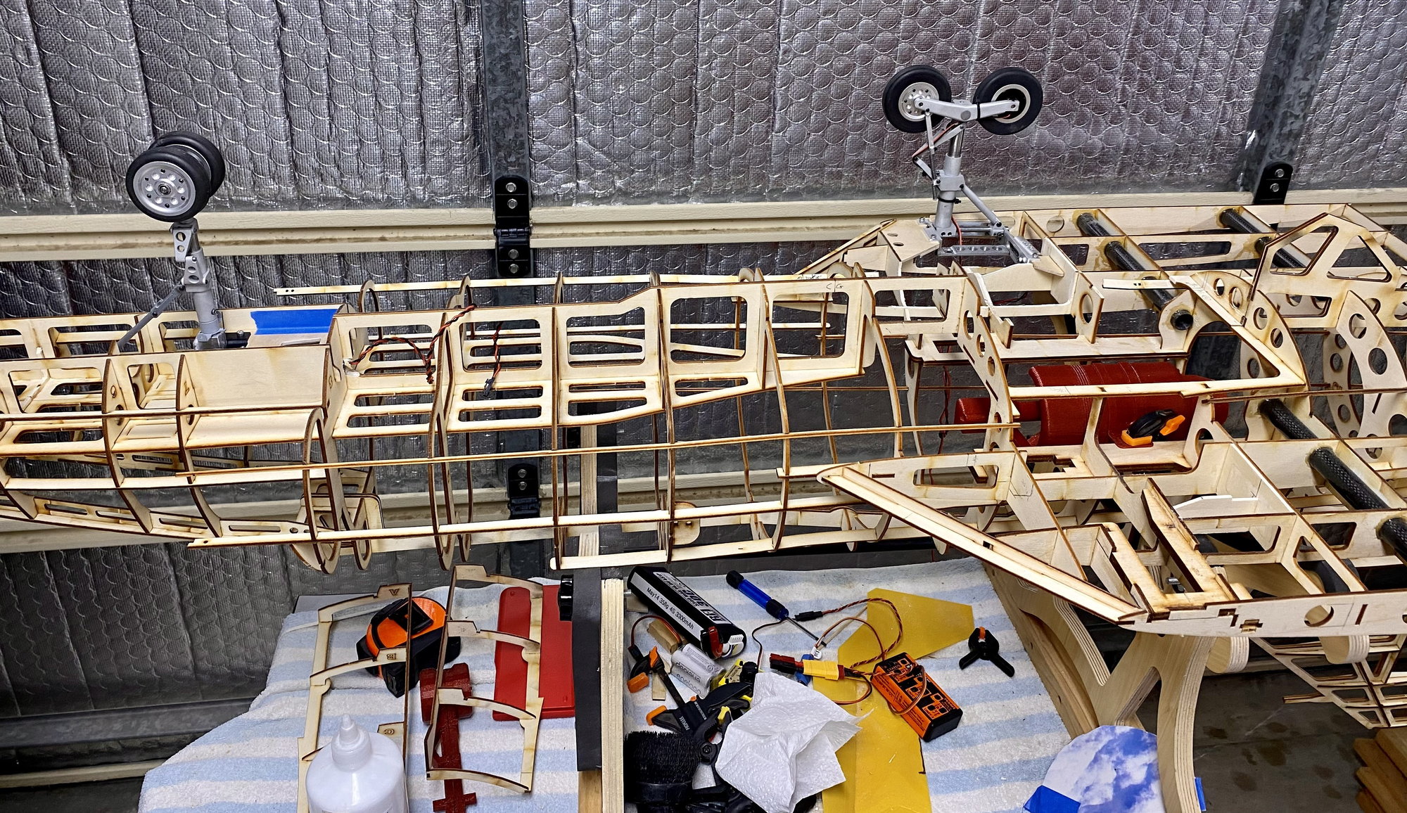
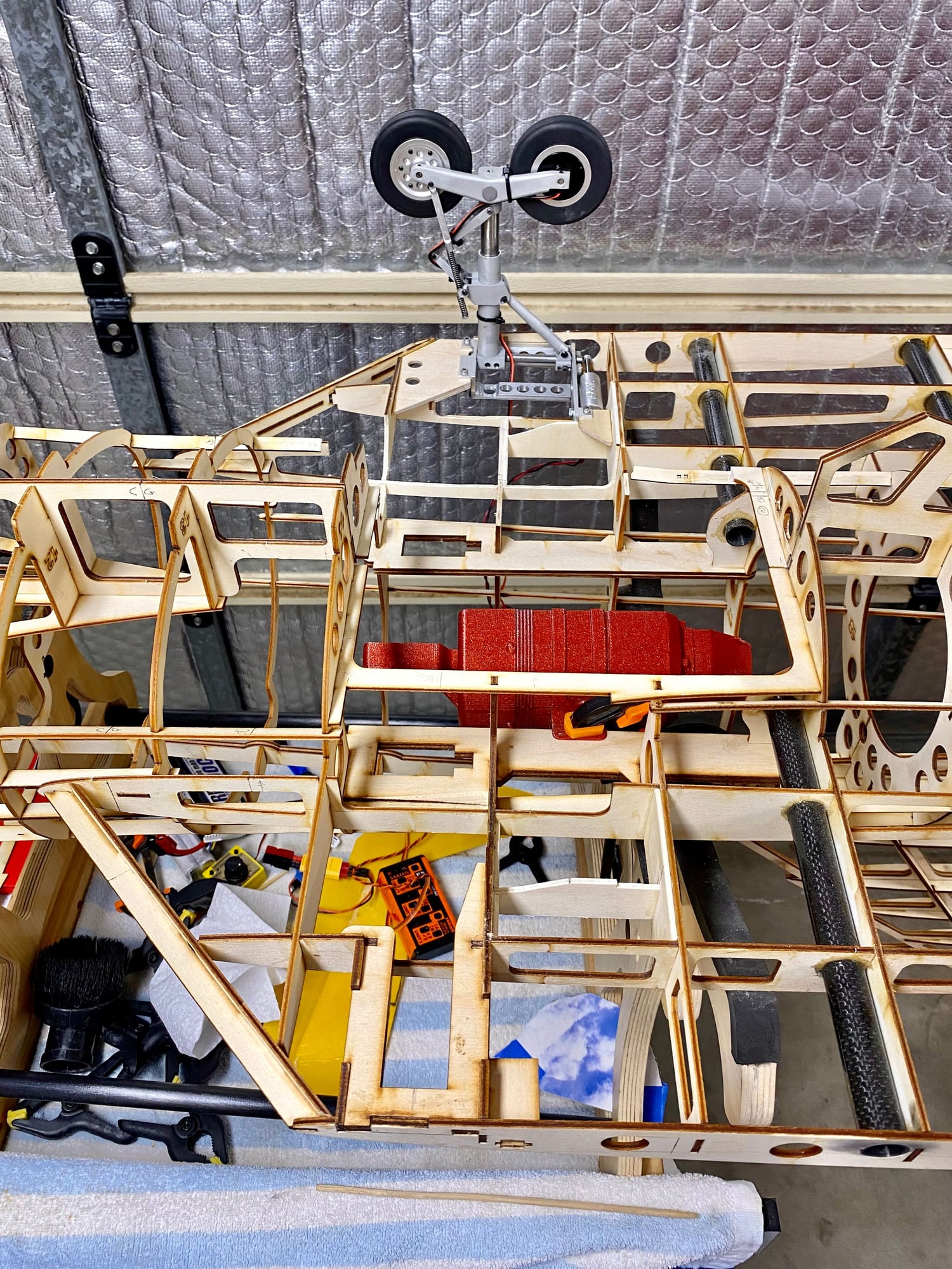
Why does it seem to take an eternity to layout one retract unit and only a few hours to replicate it on the other side (rhetorical question of the day). With a fair bit of Dremel action, a few light ply doublers, a ply mount (2 x 3mm under the attachment points), a lot of retract actuation (gear goes up, gear goes down...), more Dremel action, I installed the left main gear.
I also moved the mains aft about 10mm or so from the kit position, as I was trying to map out the shape of the doors from a scaled 3 view drawing and discovered the mains to be too far forward. The wings at the joint seem to be 10mm narrower (from the centre line) on the kit too, and the main doors at the middle overlap the EDF access hatch by quite a bit. So overall, the kit doesn�t match up with my scale reference. I�m not surprised as everything is a compromise when designing these things, it�s just a pain when I want to make the shape of the undercarriage doors and I can�t just scale it from a 3 view drawing and hit print. I�m not saying my 3 view drawing or the kit is right or wrong, it�s just that I can�t get them to match and it�s a pain when trying to scratch build the features not in the kit. ** Custom Wings � recommend you offer 1:1 3-view plans with your kits that match your kit, it would make it so much easier in all stages of the build to have a reference **. So the end result is all a bit of a compromise with the focus on making it look proportionally correct.
The picture shows the left wing complete (with gear installed) and the right in its original kit form, plus a few doublers added before the carving starts. The EDF hatch area still needs structure added. I will keep the hatch but make it narrower to accommodate the main doors while allowing sufficient room to access the turbine. Not sure why the hatch is so wide, EDF units aren�t that big and the main wheels clash with it. ** Custom Wings � recommend making the EDF hatch narrower **.
08-17-2022, 01:55 AM
#42
Thread Starter
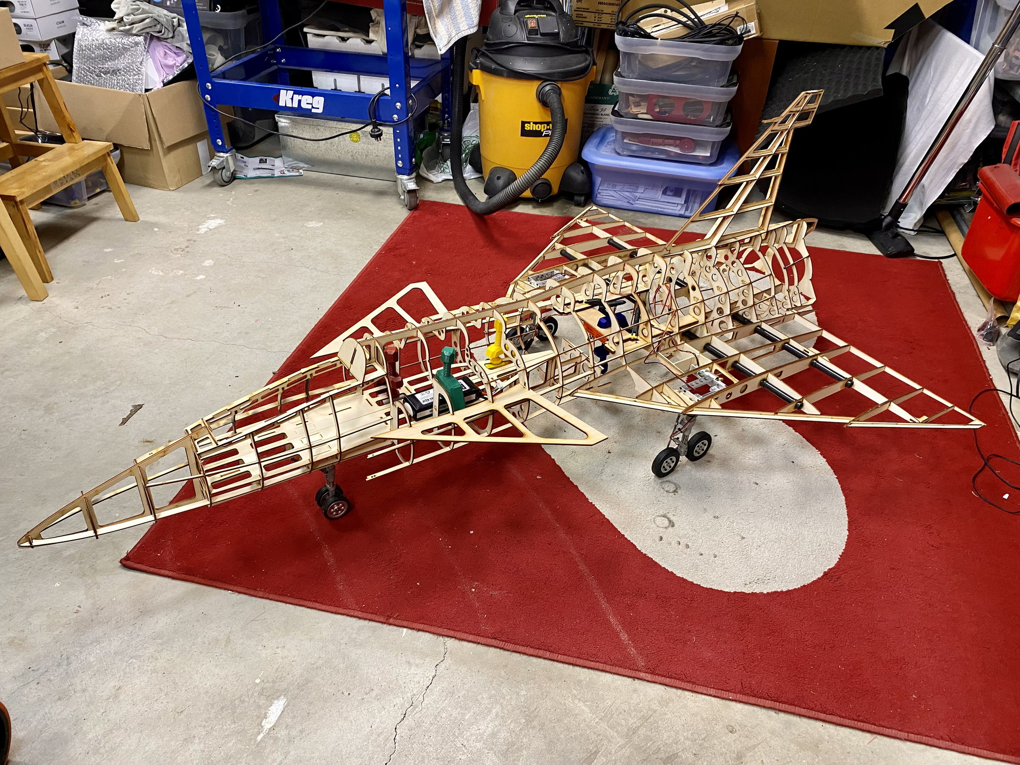
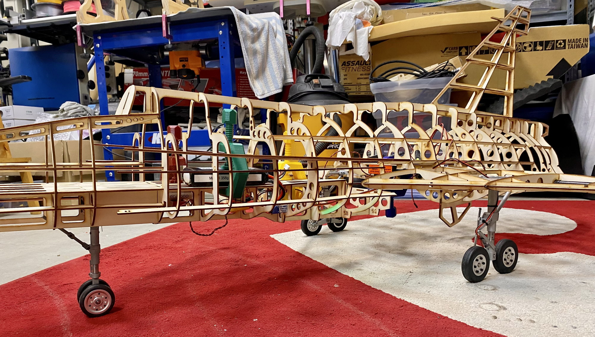
The right wing took a mere few hours to install the mains and it was quickly put on the floor for a photo op and associated celebrations. As you can see from the side view, the nose undercarriage is currently packed too much (resulting in the nose being too high), so at least it�s doing what I expected. I�ll reduce the packing next to get the length right.
The following 2 users liked this post by rustyives:
Boomerang1 (08-17-2022),
PowerGrunt (08-17-2022)
08-17-2022, 07:25 AM
#44

 08-17-2022, 01:48 PM
#49
No Ron...trying to complete a semi-scale German paper project ....a FW Flitzer......based on a Boomerang Nano and it came w/ air Robart retracts and I had them converted to electric....
08-17-2022, 02:48 PM
#50
Very interesting to see a model made from trees! So many with composite fuselages it's good to remind us that there
are alternatives. Reminds me of the Guillows rubber powered models with the vertically split fuselage halves.
One thought, most jets have a top hatch for access to fit & operate the turbine, I built a model with all access to the
turbine from the bottom but the fire risk on start up & access for a fire extinguisher worried me so I fitted a half hatch
on top purely to poke a fire extinguisher in if things go horribly wrong on start up. Your thoughts?
Happy planking when the time comes!