Community
Search
Notices
RC Pattern Flying Discuss all topics pertaining to RC Pattern Flying in this forum.

BJ Craft Element

Thread Tools
 
Search this Thread
 
Old 07-06-2017 | 10:58 AM
  #26  
 
Joined: May 2012
Posts: 11
Likes: 0
Received 0 Likes on 0 Posts
From: Shady Cove, OR
Default

I will do a document search to find out what this tool is and how it works.
Thanks for pointing me in the right direction.
Paul
Old 08-26-2017 | 12:00 AM
  #27  
papaone's Avatar
 
Joined: Mar 2005
Posts: 1,414
Received 137 Likes on 74 Posts
From: Salon, FRANCE
Default

Hello

Nice colors (pics from Bondaero)
claude
Attached Thumbnails Click image for larger version

Name:	21056255_1369542729831576_7996928551075913516_o.jpg
Views:	640
Size:	602.9 KB
ID:	2229452   Click image for larger version

Name:	21055220_1370443416408174_190775602530562903_o.jpg
Views:	796
Size:	714.3 KB
ID:	2229453  
Old 09-17-2017 | 01:59 AM
  #28  
Junior Member
 
Joined: Sep 2017
Posts: 1
Likes: 0
Received 0 Likes on 0 Posts
Default balance

Hi, I am just returning to pattern after a 15yr layoff. I have a Bj Element almost ready to fly, only snag is I can't find a balance point listed anywhere. Does anyone have any suggestions where a good starting point would be? Any suggestions would be much appreciated.
Old 09-26-2017 | 01:47 PM
  #29  
grotto2's Avatar
My Feedback: (2)
 
Joined: Feb 2003
Posts: 1,046
Received 0 Likes on 0 Posts
From: Palm Bay, FL
Default

"..we are running with the wing set at +.7* and tcan at 0* in reference to the stabs at 0*"

"T-Can should match the wing .7 positive"

Sounds like you need to put a servo on the canalizer and trim that sucker in flight.
Old 01-20-2018 | 07:42 AM
  #30  
My Feedback: (41)
 
Joined: Jan 2002
Posts: 2,347
Received 5 Likes on 5 Posts
From: Algonquin Illinois IL
Default

Hey, guys here's an update.
I have a new shipment that just arrived.
It has two new AJ New schemed Elements on it. As well as more of Scheme #1.
Here are the listings.

https://www.f3aunlimited.com/bj-craf...ginal-scheme-1

https://www.f3aunlimited.com/bj-craf...jesky-scheme-2

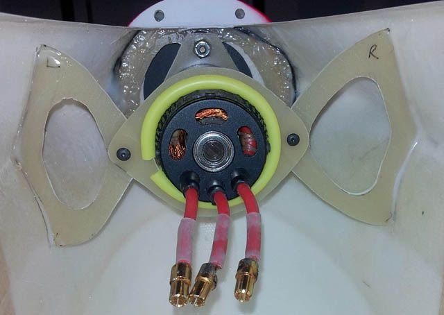
and this for a Contra setup:
https://www.f3aunlimited.com/bj-craf...r-contra-setup
Thanks for your continued support. Mike Mueller
F3A Unlimited
Old 04-04-2018 | 06:02 AM
  #31  
My Feedback: (11)
 
Joined: Apr 2002
Posts: 1,056
Likes: 0
Received 0 Likes on 0 Posts
From: Smithfield, VA
Default

What are you guys using for a manual, using the one from the invitation and/or essence?

tony
Old 04-04-2018 | 09:55 AM
  #32  
rcprecision's Avatar
My Feedback: (6)
 
Joined: Jan 2002
Posts: 447
Received 9 Likes on 7 Posts
From: Cypress, TX
Default

Link: BJ Craft USA - F3A Competition Pattern Planes under the "Resources" menu
Old 04-14-2018 | 01:40 PM
  #33  
My Feedback: (11)
 
Joined: Apr 2002
Posts: 1,056
Likes: 0
Received 0 Likes on 0 Posts
From: Smithfield, VA
Default

Has anyone tried this?

https://www.precisionaeroproducts.co...t-element-long

tony
Old 04-15-2018 | 10:27 AM
  #34  
grotto2's Avatar
My Feedback: (2)
 
Joined: Feb 2003
Posts: 1,046
Received 0 Likes on 0 Posts
From: Palm Bay, FL
Default


Old 04-15-2018 | 10:32 AM
  #35  
grotto2's Avatar
My Feedback: (2)
 
Joined: Feb 2003
Posts: 1,046
Received 0 Likes on 0 Posts
From: Palm Bay, FL
Default


Last edited by grotto2; 04-15-2018 at 10:46 AM.
Old 04-15-2018 | 10:43 AM
  #36  
grotto2's Avatar
My Feedback: (2)
 
Joined: Feb 2003
Posts: 1,046
Received 0 Likes on 0 Posts
From: Palm Bay, FL
Default


Old 04-15-2018 | 02:13 PM
  #37  
grotto2's Avatar
My Feedback: (2)
 
Joined: Feb 2003
Posts: 1,046
Received 0 Likes on 0 Posts
From: Palm Bay, FL
Default


Old 04-20-2018 | 10:03 AM
  #38  
grotto2's Avatar
My Feedback: (2)
 
Joined: Feb 2003
Posts: 1,046
Received 0 Likes on 0 Posts
From: Palm Bay, FL
Default


Vent template
Old 04-21-2018 | 01:32 PM
  #39  
My Feedback: (1)
 
Joined: Jul 2007
Posts: 630
Likes: 0
Received 1 Like on 1 Post
From: College Station TX
Default My Element Down thrust?

Hey guys, my Element down thrust with the stab at an accurate 0° is -4.5° down. This is like 3.5°more than I normally use. The stab is non adjustable. My bolted on t-cant is.55°+ to the stab and my wing is set @ .7°+ to the stab which means my t-cant is .15° negative to the wing. The real big issue here is the huge amount of down thrust @ 4.5° negative? From what I have read most people are using around a -1° to -1.5° down thrust.Wing is adjustable as well as t-cant and painted nose ring (3 colors) could be re done with a lot of work so that could be re- done! Grr Any thoughts on this will be welcome and aporeciated .
Old 04-23-2018 | 03:08 PM
  #40  
grotto2's Avatar
My Feedback: (2)
 
Joined: Feb 2003
Posts: 1,046
Received 0 Likes on 0 Posts
From: Palm Bay, FL
Default

Old 05-01-2018 | 11:12 AM
  #41  
grotto2's Avatar
My Feedback: (2)
 
Joined: Feb 2003
Posts: 1,046
Received 0 Likes on 0 Posts
From: Palm Bay, FL
Default


Rear T-can stiffener. 1/4" carbon-end grain balsa sandwich. 68mm ahead of previous bulkhead.


Front T-can stiffener. 1/4" carbon-end grain balsa sandwich.
Old 05-02-2018 | 05:41 PM
  #42  
grotto2's Avatar
My Feedback: (2)
 
Joined: Feb 2003
Posts: 1,046
Received 0 Likes on 0 Posts
From: Palm Bay, FL
Default

Originally Posted by underdw
Good idea and worth the time! The china-wood in my canopy failed (after a few years).
That's not the canopy. It's the turtledeck behind the canopy underneath the T-Canalyzer. There have been reports of canalyzer flutter.

Last edited by grotto2; 05-02-2018 at 05:48 PM.
Old 05-04-2018 | 12:51 PM
  #43  
grotto2's Avatar
My Feedback: (2)
 
Joined: Feb 2003
Posts: 1,046
Received 0 Likes on 0 Posts
From: Palm Bay, FL
Default


No wheel collars. No lost wheels.
Old 05-04-2018 | 04:36 PM
  #44  
My Feedback: (11)
 
Joined: Apr 2002
Posts: 1,056
Likes: 0
Received 0 Likes on 0 Posts
From: Smithfield, VA
Default

Which axles are those?

how do you mount the wheel pants?

want to sell a pair of those stiffeners?

tony

tony

Last edited by vatechguy3; 05-04-2018 at 04:41 PM.
Old 05-04-2018 | 05:18 PM
  #45  
grotto2's Avatar
My Feedback: (2)
 
Joined: Feb 2003
Posts: 1,046
Received 0 Likes on 0 Posts
From: Palm Bay, FL
Default

Originally Posted by vatechguy3
Which axles are those?

how do you mount the wheel pants?

want to sell a pair of those stiffeners?

tony

tony
Those are Dubro axles. The wheels are put on and the axles are measured and cut. The end of the axle is heated to orange, cooled, and a small flat is ground on one side. Then a hole is drilled (maybe #60) at the ground point thru the axle to accept a short piece of .032 aviation safety wire. A washer or washers are used for spacing. You will not lose a wheel in a contest using this technique!
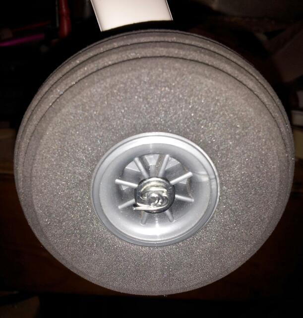
I fly on turf, so there will be no pants and the associated hassle.
Wheels are Dubro Lite 2-3/4".
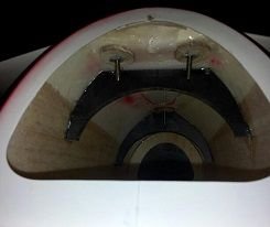
I cannot guarantee the function of the stiffeners as the plane has not flown yet, so you're on your own. They were designed with scraps of information I gathered word-of-mouth. Kyuho Lee checked the photos and felt it functionally matched the structure he added on his Agenda, but I deviated from what he actually did by adding the front stiffener instead of carbon tow around the front screws.
What? No comments about the tailwheel?
-Ron
Old 05-17-2018 | 09:10 AM
  #46  
grotto2's Avatar
My Feedback: (2)
 
Joined: Feb 2003
Posts: 1,046
Received 0 Likes on 0 Posts
From: Palm Bay, FL
Default


3D printed canalyzer shims to simultaneously adjust incidence and tilt. These are the four rejects. The fifth one was correct and is installed under the canalyzer leading edge. The advantage of 3D printing is precise control of thicknesses (better than 0.5mm tolerance was needed in this case) and reproduceability. It could be done with sandpaper and wood, too, but this was a whole lot more fun.
Old 05-17-2018 | 09:30 AM
  #47  
My Feedback: (1)
 
Joined: Jul 2007
Posts: 630
Likes: 0
Received 1 Like on 1 Post
From: College Station TX
Default

Process looks good. What did you set yhe incidence at as relates to wing?
Old 05-17-2018 | 11:52 AM
  #48  
grotto2's Avatar
My Feedback: (2)
 
Joined: Feb 2003
Posts: 1,046
Received 0 Likes on 0 Posts
From: Palm Bay, FL
Default

Originally Posted by pattratt
Process looks good. What did you set yhe incidence at as relates to wing?
I set it the same as the wing, pattratt. It seems to be the consensus here.
Old 05-17-2018 | 12:33 PM
  #49  
My Feedback: (1)
 
Joined: Jul 2007
Posts: 630
Likes: 0
Received 1 Like on 1 Post
From: College Station TX
Default

Ok, thanks
Old 05-24-2018 | 12:03 PM
  #50  
grotto2's Avatar
My Feedback: (2)
 
Joined: Feb 2003
Posts: 1,046
Received 0 Likes on 0 Posts
From: Palm Bay, FL
Default


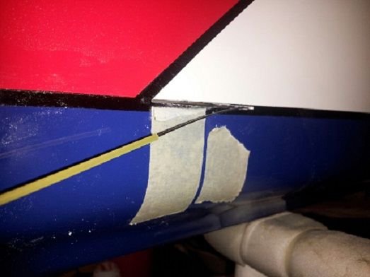
Rigging Pull-Pull rudder.
Slot is located by measuring for the point in the fuselage where the width=cable spacing, 2.5 inches in this case. The 2.5" comes from the servo arm and rudder arm hole spacing, which are equal. Servo arm and rudder arms were mounted vertically to lie on the top of the black paint line as shown. Cables were first rigged to the servo arm and then the servo installed. To retrieve the cables from the fuselage, I pushed a small nylon rod into the exit slot and fed the cable into it from the front. Pull the nylon rod out and the cable is magically in place.


Contact Us - Archive - Advertising - Cookie Policy - Privacy Statement - Terms of Service

Copyright © 2026 MH Sub I, LLC dba Internet Brands. All rights reserved. Use of this site indicates your consent to the Terms of Use.