


FRSky Taranis Beginners Support Group
 05-26-2019, 06:41 PM
#101

Yep, it works. Now save your setup for the tug plane, and attach. I'll edit that one, and respond with the why's and wherefore's of what I did.
Ted
 05-27-2019, 03:31 AM
#102

Join Date: Sep 2015
Location: Bellingen NSW Australia
Posts: 332
Likes: 0
Received 0 Likes
on
0 Posts
Ted,
I will have to leave this until morning. I'm very tired and find that I am getting more confused the more I try to sort it.
I will be a bit brighter in the morning.
Truth is, I am not at all clear about Sources, channels, Ail and IAil CH etc. Need to do some more reading.
Many thanks for doing this for me.
Jim.
 05-27-2019, 07:45 AM
#103
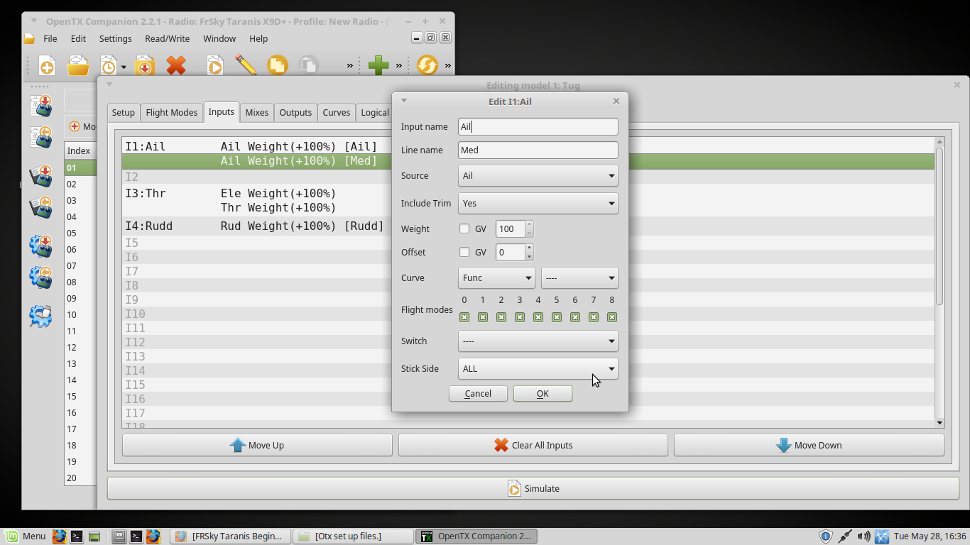
Fully understand - my responses were also in the late hours, so that can contribute to the muddle. Here are a few definitions that may assist:
Sources -Anything that provides a value to be used or modified.
Mixer - Where you link a Source so that it goes to the correct Channel (servo).
Sources -Anything that provides a value to be used or modified.
- On the Inputs tab drop down, these are the actual sticks, sliders, knobs and switches that send some value to the rest of the system. The variable ones (sticks, sliders, knobs) send a value in the range of +100 to -100, with 0 in the middle. Switches send only +100, 0, -100 (3 position) or +100/-100 (2 position).
- These are abbreviated Ail, Ele, Thr, Rud (main sticks), S1 and S2 for the knobs, RS and LS for the right and left sliders, and SA through SH for the switches.
- There are many things accepted as Inputs, that are not for beginners to think about, but do add a lot of flexibility to the system - Trim switches can be used as a source, "Logical Switches", Channels used as sources, outputs coming from a buddy box, and others. Ignore all of those for now.
- Modification can include, among others: Linking a trim switch to influence the value from a main stick. Setting a rate or rates. Setting expo. Applying curves.
- It does not matter in what order they are listed on the Inputs tab. If there is not going to be any modification to the values put out by a Source, it does not have to be listed at all.
- In other drop downs, Inputs will be shown by their place on the Inputs list, and whatever name (if any) they were given. For example, "I2:Ele" means "Use the value resulting from item #2 on the Inputs screen, which is named Ele". Not to be confused with plain "Ele", which is the actual stick and the raw value it is sending.
Mixer - Where you link a Source so that it goes to the correct Channel (servo).
- This may be a simple "send I2:Ele results to Channel 2".
- Multiple sources can be combined to modify the servo movement, such as traditional "mixing", like using aileron control to change the rudder slightly when doing turns.
- Or, one source can be used to control several Channels (servos).
05-27-2019, 02:21 PM
#104
Join Date: Sep 2015
Location: Bellingen NSW Australia
Posts: 332
Likes: 0
Received 0 Likes
on
0 Posts
.........................
...................................
...................................
- In other drop downs, Inputs will be shown by their place on the Inputs list, and whatever name (if any) they were given. For example, "I2:Ele" means "Use the value resulting from item #2 on the Inputs screen, which is named Ele". Not to be confused with plain "Ele", which is the actual stick and the raw value it is sending.
I have moved my triple rates lines back to the inputs window as instructed here: OpenTx - Key concepts
Your post above will help me sort it this morning.
More later,,,,,,,
Jim.
05-27-2019, 03:04 PM
#105
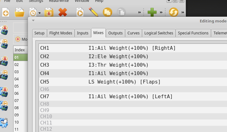
It was a very rainy day, so I recreated your plane based on what was posted, set up the way I would do it. Was unsure what the "cut" for Ch5 was for, since I couldn't see the other screens, so skipped over that. Here are some screenshots, plus the otx file (renamed txt).
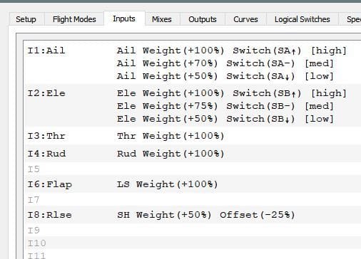
All rates and changes to a Source done here. Thr and Rud shown because they have trim applied. Flap did not have to be listed, but was for consistency and in case there might be future refinements.
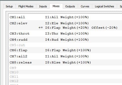
Most is just pass through of Inputs to a Channel. Flap operation adds a bit of elevator.
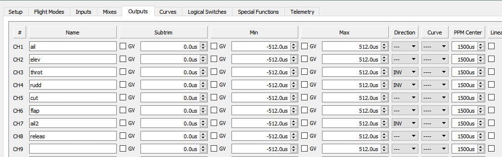
All servo reversing done here - the lines that say "INV".
All rates and changes to a Source done here. Thr and Rud shown because they have trim applied. Flap did not have to be listed, but was for consistency and in case there might be future refinements.
Most is just pass through of Inputs to a Channel. Flap operation adds a bit of elevator.
All servo reversing done here - the lines that say "INV".
05-27-2019, 03:22 PM
#106
Join Date: Sep 2015
Location: Bellingen NSW Australia
Posts: 332
Likes: 0
Received 0 Likes
on
0 Posts
Ted,
That is good and at first quick read through, is pretty much what I arrived at in my draft last night.
I will now have to look at your "INV" entries, as I am puzzle by this.
Also, I will get to make up the mix and return it to you asap. I am a bit over wrought with fatigue from taking on too much stuff.
I greatly appreciate your continued assistance.
I will follow through.
Edit: I have also got to sort out my saving process as I have been getting them mixed up. I will need to do this before importing and saving your draft for me. I will need to differentiate between draft and test set ups, such as yours and several of mine, before I go too far.
Also, I have one of our rare low humidity days that are suitable for spraying acrylic lacquer. So, I will be outside most of the day.
By the way, I have named my engine stop or "kill" switch "cut".
Jim.
Last edited by Jim.Thompson; 05-27-2019 at 03:26 PM.
05-27-2019, 05:13 PM
#107
Join Date: Sep 2015
Location: Bellingen NSW Australia
Posts: 332
Likes: 0
Received 0 Likes
on
0 Posts
Ted,
I have struck a minor problem when using Companion. On two occasions this happened.
I was going really good with getting the hang of it and almost completing my draft before posting it for your appraisal and editing.
When I went to edit one line, all entries below that line disappeared!
I will adopt the habit of saving after every entry in future.
Now............I will try to remember all I did and replicate it.
Jim.
Edit:
I will try again; this time I'll take screenshots after every line I enter. I wonder if this problem behavior has anything to do with me using Companion in Linux Mint?
Or, is it a common (or not uncommon) phenomena?
Jim.
Last edited by Jim.Thompson; 05-27-2019 at 07:03 PM.
05-27-2019, 07:50 PM
#109
Join Date: Sep 2015
Location: Bellingen NSW Australia
Posts: 332
Likes: 0
Received 0 Likes
on
0 Posts
I will try opening Companion in my old Win7 partition, which I still use offline, and give a go from the beginning again.
There is a good outcome as a result of all this hassle; I am learning to enter the correct (I think) parameters. I have to do it countless times before it stablises.
I will post a file of a partly done tug plane set up.
It will have only basic functions; I will omit the engine cut (kill) switch and the aerotow release for the time being. I have lost count of the number of times I have attempted to do so, only to lose everything and have to go back to Line #1!
However, that is also ok. It will provide me/you with a good look at the tripple rates, the input window and the mixes and allow you to check if I have done them correctly so far.
If and when that is satisfied, I will move onto entering the release and cut lines.
Better days ahead.
Jim.
05-27-2019, 08:27 PM
#110
Overall looking good. What is the reasoning behind the offset of -8 for the elevator input? Trying to get the surface centered?
You noted my use of "INV" on outputs for servo reversing previously. As you have done on elevator, you can change the weight from +100 to -100 for the same effect. I like to do it in outputs, for cases where I have two servos being driven by the same source, but one has to be reversed to move the surface correctly. Some setups can get messy trying to do the reversing for one of a two servo config via Inputs or Mixing, but other than that, there is no strong argument for doing it either way.
It looks like you are experimenting with logical switches, also. If you'd like, I'll share my use of those for an engine kill function.
05-27-2019, 09:18 PM
#111
Join Date: Sep 2015
Location: Bellingen NSW Australia
Posts: 332
Likes: 0
Received 0 Likes
on
0 Posts
The way forward for me I think is to delete all saved files.
Then start again with only one model set up.
At this stage, I cannot remember why I offset the elevator...........that was some time ago.
All I know is I did not put that in the file that edited and that I meant to send you this morning.
Confusion, confusion and more confusion.
Last edited by Jim.Thompson; 05-27-2019 at 09:53 PM.
05-27-2019, 10:11 PM
#112
Join Date: Sep 2015
Location: Bellingen NSW Australia
Posts: 332
Likes: 0
Received 0 Likes
on
0 Posts
Ted,
I have entered part of the set up in short form, just to test out my save and recover file system.
I will send you a screenshot and the .txt file to see if they arrive the same.
Please check and advise.
If all good, I will proceed to complete the set up.
No point in wasting any more time with it until this part of my system is working reliably.
Thanks,
Edit: I am beginning to suspect that I have multiple problem in my Companion application. It is unstable to start with. Now, I suspect that it is not over writing a file when I hit save.
Jim.
Last edited by Jim.Thompson; 05-27-2019 at 10:28 PM.
 05-27-2019, 10:41 PM
#114
Join Date: Sep 2015
Location: Bellingen NSW Australia
Posts: 332
Likes: 0
Received 0 Likes
on
0 Posts
Ted,
I might have to walk away from this for a day or two. I will try my Win7 version of Companion tonight and limit my session to 1 hour. If I don't start to see the light after that, I will pack it in for a while.
The more I work on it, the more crazy it appears.
Sorry..................
Jim.
I might have to walk away from this for a day or two. I will try my Win7 version of Companion tonight and limit my session to 1 hour. If I don't start to see the light after that, I will pack it in for a while.
The more I work on it, the more crazy it appears.
Sorry..................
Jim.
05-28-2019, 04:14 AM
#115
Looking good! You're well on the way for the setup. You clearly have the "logic chain" of how things flow understood.
For Inputs, there is no multiplex box. The sub lines are essentially just a series of choices - "Modify using these values OR these values OR these values, etc." with the OR controlled by a switch or switches.
The developers kept the fancy stuff: ADD this to that, REPLACE this with that, etc. to the Mixer.
I seem to remember old discussions where purists advocating removing the trim options from the Inputs screen, as adding a trim lever value to a source is more properly a mix. But the developers refrained, figuring that it would lead to other unwanted complications in complex situations.
Last edited by tedsander; 05-28-2019 at 04:17 AM.
05-28-2019, 05:04 AM
#116
Join Date: Sep 2015
Location: Bellingen NSW Australia
Posts: 332
Likes: 0
Received 0 Likes
on
0 Posts
What I have decided to do next time I get to tackle it, is to abandon my use of Companion to edit set ups. Instead, I will try starting them in the transmitter, which I have infinitely less problems with, then loading then set up into Companion for posting/evaluation/ etc.
I am having far too many problems with Companion, wasting many hours with the instability and such. I tried my Win7 version of Companion and found it to be very similar to the version I have in my Linux Mint 19 OS.
I cannot duplicate the consistent behavior of it that other users report.
Sorry about that...............got to accept ones limitations etc.
Tonight, I set up a new Tug plane mix in my Taranis X9D Plus which seems to be fine. I checked out all tripple rates etc by driving a rx. and servos set up in front of me here on my desk. Far, far easier than dealing with that finicky simulator in Companion.
My apologies to the hard working developers about this, but that is my honest experience.
I will load the Tug plane set up from the tx. to Companion, create a .txt file, and post it here.
Thanks again,
Edit: Here is the file. I have added the flap to elevator compensation in this set up. Please note: I had to include offset to return the elevator to neutral. Is this the correct way to do it?
Jim.
Last edited by Jim.Thompson; 05-28-2019 at 05:27 PM.
05-28-2019, 08:29 PM
#117
For elevator, better would be to go over to the Outputs tab, and use the "PPM Center" column to get the elevator centered. Then you don't need the offset for elevator in mixing. But, 20% is an awful lot of adjustment to get things centered. It might be time to look at your servo and reset the arm on the shaft so you need less adjustment on the radio.
What does the ch 5 cut do in the plane? A separate servo? In mixing, your MAX line had 150%. Since the Output for Ch 5 is set for max and min of +/-100%, your 150% is getting chopped off there. So you might as well just make it 100% in the mixing.
For ail, elev, and ail2 on the outputs page, the min and max should be for the maximum the surface can physically move, before binding or having the servo stall. Then cut the weight over on the inputs page to be whatever you want the surface to really move to when on high (ie - 75%), and reduce the other rates proportionally. This gives you extra, so when on high rates and full stick, the elevator can still move even more when you activate flaps.
05-28-2019, 09:43 PM
#118
Join Date: Sep 2015
Location: Bellingen NSW Australia
Posts: 332
Likes: 0
Received 0 Likes
on
0 Posts
But, 20% is an awful lot of adjustment to get things centered. It might be time to look at your servo and reset the arm on the shaft so you need less adjustment on the radio............
What does the ch 5 cut do in the plane? .........................
So you might as well just make it 100% in the mixing.................
For ail, elev, and ail2 on the outputs page, the min and max should be for the maximum the surface can physically move, before binding or having the servo stall. Then cut the weight over on the inputs page to be whatever you want the surface to really move to when on high (ie - 75%), and reduce the other rates proportionally. This gives you extra, so when on high rates and full stick, the elevator can still move even more when you activate flaps.
I have yet to power the full (completed) model up with this set up. I will follow that when I do so.
Progress happens!
Many thanks again Ted.
Last edited by Jim.Thompson; 05-28-2019 at 09:47 PM.
05-29-2019, 07:50 AM
#119
That also seems to be a viable option that I did not think about. However, I like the first option better. That is because whatever elevator compensation % I choose here now, only flight test will verify. It is common that this has to be adjusted and I fully expect this to be the case for my Tug. I don't want to be moving servo arm position after full set up and the first flight, that is, unless absoluteley necessary.
.
.
So, change the spline the servo arm goes to, to get back the 20% - more or less. Then fine tune using PPM center to get it exact, where you might only have to give up 5% of rotation, or even less.
For flight testing - use the trim levers. Than transfer the trim settings to the subtrim (google on how to do that easily on the radio). Done.
05-29-2019, 02:34 PM
#120
Join Date: Sep 2015
Location: Bellingen NSW Australia
Posts: 332
Likes: 0
Received 0 Likes
on
0 Posts
05-29-2019, 08:25 PM
#121
Whoops, I didn't see the real issue -
.
You have flaps set to operate using values from +100 to -100, depending on the position of LS.
With LS at the top of it's travel, (flaps up) it is 100%.
On Ch2, the Elevator Stick at neutral is 0%. But the second mix line instructs to add 20% of LS to that, so the elevator at neutral is now +20%. You dialed that out using the offset for the elevator.
Instead, put the offset on the second line for Ch2 (LS Weight (+20%) Offset (-20%) Now the elevator should behave normally, without a need for offset or PPM center, but will still get the same compensation with flaps down.
BTW - Because you are going from +100 to -100 with LS, that is a range of 200. 20% of 200 is 40. So the elevator moves up 40% at full down flaps (well, you don't see a full 40%, because you cut down the throws in the output from the default 100%...but you'll still see a ton of up elevator happening with flaps.) A quick solution is to put much smaller numbers in the LS mix line for channel 2 - like weight of 5% and offset of -5%. That will give 10% elevator compensation. Just remember, after flight testing, that whatever you use for compensation should use the same digits (3% weight and -3% offset, 6% weight, -6% offset, etc.)
If the above doubling seems ungainly, assign LS as an Input with a weight of +50, and an offset of -50. This cuts what LS uses for a range in half.
Then use that new source for channel 6 at 100% and for the second line of Ch2, with just a weight (20% or whatever). You linkages on the plane won't have to change at all.
In a little over a day, I'll be going out of town for a bit more than a week, so will not have access to this forum. Hope the above didn't hurt your brain too badly!
05-29-2019, 09:49 PM
#122
Join Date: Sep 2015
Location: Bellingen NSW Australia
Posts: 332
Likes: 0
Received 0 Likes
on
0 Posts
Whoops, I didn't see the real issue -
.
You have flaps set to operate using values from +100 to -100, depending on the position of LS.
With LS at the top of it's travel, (flaps up) it is 100%.
On Ch2, the Elevator Stick at neutral is 0%. But the second mix line instructs to add 20% of LS to that, so the elevator at neutral is now +20%. You dialed that out using the offset for the elevator.
Instead, put the offset on the second line for Ch2 (LS Weight (+20%) Offset (-20%) Now the elevator should behave normally, without a need for offset or PPM center, but will still get the same compensation with flaps down..................
BTW - Because you are going from +100 to -100 with LS, that is a range of 200. 20% of 200 is 40. So the elevator moves up 40% at full down flaps (well, you don't see a full 40%,...................
because you cut down the throws in the output from the default 100%...but you'll still see a ton of up elevator happening with flaps.) A quick solution is to put much smaller numbers in the LS mix line for channel 2 - like weight of 5% and offset of -5%. That will give 10% elevator compensation. Just remember, after flight testing, that whatever you use for compensation should use the same digits (3% weight and -3% offset, 6% weight, -6% offset, etc.)...........
If the above doubling seems ungainly, assign LS as an Input with a weight of +50, and an offset of -50. This cuts what LS uses for a range in half.
.............................
.............................
Many thanks again Ted.
Jim.
p.s. I am making progress with the understanding of how this system works.
05-30-2019, 05:45 AM
#123
Let's correct:
Set up an Input using LS as a source, with a weight of +50, and an offset of -50. This cuts the range from +100/-100 to 0/-100
Then use that new source in the Mixer for your flap channel, but set the weight to +200, with an offset of +100 This restores the range back to +100/-100. So we cut the signal in half on the input side, but doubled here for this line in the mixer. - so the flap servos still move their full amount as before.
Meanwhile, on the flap to elevator mixer line, use the same new input, but only put in whatever weight you want. Since the incoming will be from 0 to -100, your 20% (or whatever) will be a true 20% and not double on you to 40%....
No offset to deal with for adjusting the final elevator compensation.
Take a peek at Mike Shellim's site, where he discusses setting up a knob to control that 20% in flight - so while in the air you can dial the compensation up and down to find the correct amount. No more tedious fly, land, adjust, and repeat. You can even get the radio to announce the current % while flying, so you can then later "hard code" it once you find the good number. In flight adjusters with OpenTx
Hope you get your Companion issues figured out. Kilrah, over in the other group, is truely a master of the system, having been heavily involved since the early days,
Last edited by tedsander; 05-30-2019 at 05:48 AM.
05-30-2019, 01:28 PM
#124
Join Date: Sep 2015
Location: Bellingen NSW Australia
Posts: 332
Likes: 0
Received 0 Likes
on
0 Posts
Geez, now I get to blame the late night and being tired. I blew my second example.
Let's correct:
Set up an Input using LS as a source, with a weight of +50, and an offset of -50. This cuts the range from +100/-100 to 0/-100
Then use that new source in the Mixer for your flap channel, but set the weight to +200, with an offset of +100 This restores the range back to +100/-100. So we cut the signal in half on the input side, but doubled here for this line in the mixer. - so the flap servos still move their full amount as before.
Meanwhile, on the flap to elevator mixer line, use the same new input, but only put in whatever weight you want. Since the incoming will be from 0 to -100, your 20% (or whatever) will be a true 20% and not double on you to 40%....
No offset to deal with for adjusting the final elevator compensation..............
Take a peek at Mike Shellim's site, .................. In flight adjusters with OpenTx................
Hope you get your Companion issues figured out. Kilrah, over in the other group, is truely a master of the system, having been heavily involved since the early days,
More later when I try your above alternative for the flaps.
Edit: I looked at Mike Shellims page again, it is clearly very good. However, I have read some of his pages and found them immediately lacking in enough information for the beginner to get started with his instructions. I've then stopped reading...
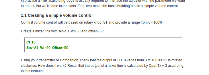
I met an example of this immediately at the start of this otherwise very good list of instructions. Please see screenshot with a mention of "src" without any nomenclature decoding, or glossary of terms.
What does this mean please Ted?
My apologies in advance for what is probably a very silly question. A question which I would never dare ask over on the rcgroups!
Edit: Please ignore the question. I've since been tipped off that it is "source".
I should have known!
Jim.
Last edited by Jim.Thompson; 05-30-2019 at 09:10 PM.
05-31-2019, 04:45 AM
#125
Yep, one of the hurdles - besides the sometimes cryptic abbreviations in OpenTX (especially when trying to do the work on the radio itself!) Each forum author (me included) seems to come up with their own way of presenting the "code" , which can compound the lack of clarity. I like screenshots the best, but that doesn't lend itself to discussions beyond one "tab" (in Companion) very well.
That said, for years I had a Futaba 14MZ, that could potentially do most of the fancy stuff. I was never able to crack the terminology to figure out how to implement things. I too with the Taranis had the learning curve about Sources, Inputs, Mixing, etc. But it now seems to be gelling enough that I can get almost anything working the way I want, for my comparatively simple needs. Just don't ask about Telemetry or LUA!
That said, for years I had a Futaba 14MZ, that could potentially do most of the fancy stuff. I was never able to crack the terminology to figure out how to implement things. I too with the Taranis had the learning curve about Sources, Inputs, Mixing, etc. But it now seems to be gelling enough that I can get almost anything working the way I want, for my comparatively simple needs. Just don't ask about Telemetry or LUA!