


Power Distribution
 12-11-2022, 07:23 AM
#1
When I built my first Ziroli Bearcat in the 80’s, the receivers would occasionally have interference from ignition engines. I changed switches, batteries, receivers, but never got a handle on it. It always seem to occur during maneuvers. The more I flew the worse it got. After the third flight on one occasion when I was trying to trouble shoot the problem, I lost radio control. The airplane made a big hole in the ground with the 100cc engine a foot below the surface.
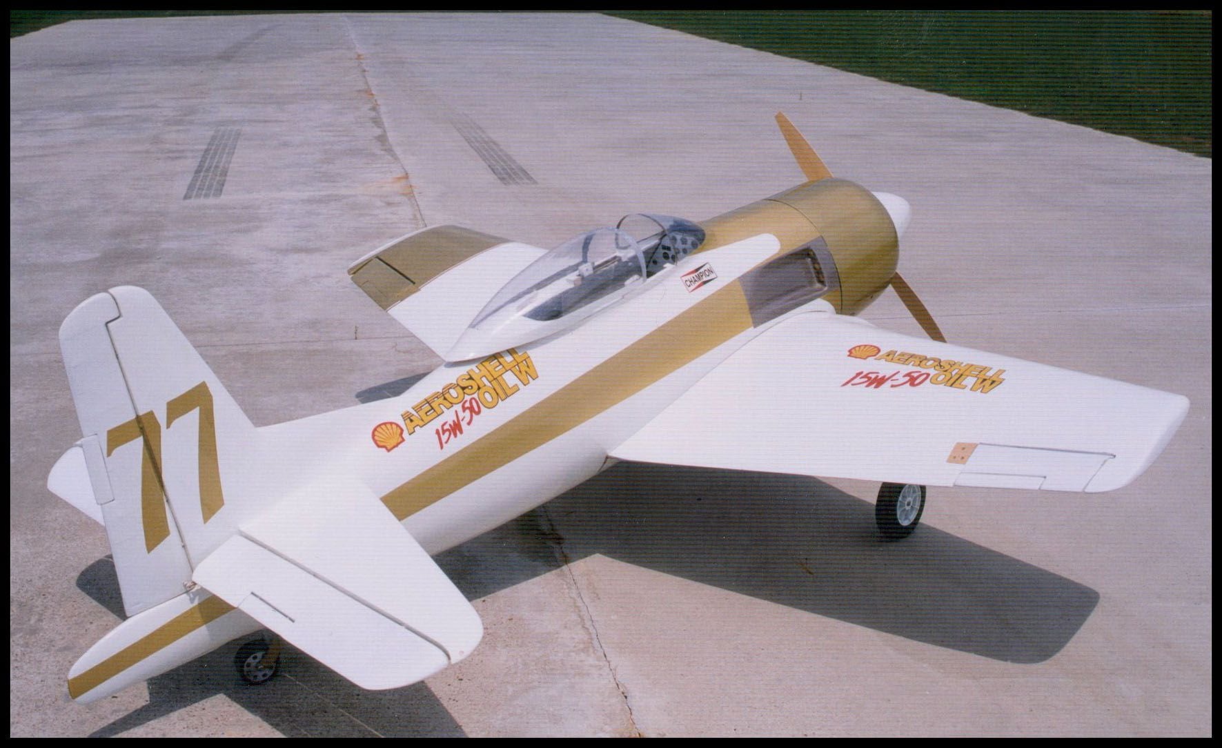
The next Bearcats I built I had a lot more time in them. Keep in mind I was cutting every part from plans; not using kit cutters. The next couple of Bearcats I built had more detail, some with rivets and custom built landing gear that articulated like the real one. They were built after “Rare Bear” the Reno racer. I made a mold for the canopy then vacuum formed the racing canopy. The wings were clipped and the ailerons were half the width of the originals like the real airplane.
With this much skin in the game, I thought about my ignition issues. I surmised with all the big servos it may have been dropping the voltage in the receiver enough during maneuvers to let the ignition interfere. It always got worse with more flights.
My solution then was to run 2 receivers to distribute the load. I never had another problem. Many good flights.
 12-11-2022, 07:23 AM
#2
Fast forward. I spent a number of years out of the hobby as I was restoring and building full size cars. I am caught up and decided to build another airplane; this time just a kit, not from plans. I have 6 heavy duty servos and a few other normal servos. I looked at my receiver and it is a much smaller Futaba R617FS. I decided to take a more analytical approach to servo draw.
I have not been able to find specs on the receiver although I have seen much internet speculation which doesn’t mean much. I also build circuits as a hobby so I have an idea of what some can handle. Keep in mind there is a huge difference in small term draw during maneuvers and long term draw.
One Hitec Hs-625MG servo draws .5 amps during static movement. Stall current of 2.5 amps. We don’t stall a servo during maneuvers but is certainly more than a 1/2 an amp. With 4 servos for the wings consider an aileron roll using 2-3 amps alone. DO a rolling circle and you have elevator adding a bit as well.
One of the circuits I made some time back was a relay board for automotive application. I could not get the amps needed out of a circuit so I waterjetted copper circuit parts. Even doing so I was only able to come up with 15 amps at 12 volts with substantially thick copper to keep it from heating up more than acceptable.
What is acceptable? Conventional thought is circuit rise of 10° but keep in mind that is a continues or average draw not transitory. I have little faith the receiver alone is adequate. I ordered a distribution box but has been on back order.
Keep in mind a servo plug on a normal receiver battery is only good for 3A continuous. The wire on servo plugs being 22awg have a voltage drop of “.6” over a 3 foot extension. A 22awg wire has a drop of “.24” over 3 feet.
 12-11-2022, 07:26 AM
#4
My solution was to make my own circuit to distribute power. In this day an age we are blessed with a few really cool online tools. At www.expresspcb.com you can download software to build circuits for free. When your circuit is designed you can hit upload and order them. The come to your mailbox a few days later.
Cost is generally high for low number, for example: I make automotive solid state turn signal circuits for which I have a patent on. I can order 2 and they are about $110. I can order 25 and they drop to about $20 each. I can order enough and get them under $10 a piece.
Cost is generally high for low number, for example: I make automotive solid state turn signal circuits for which I have a patent on. I can order 2 and they are about $110. I can order 25 and they drop to about $20 each. I can order enough and get them under $10 a piece.
12-11-2022, 07:29 AM
#5
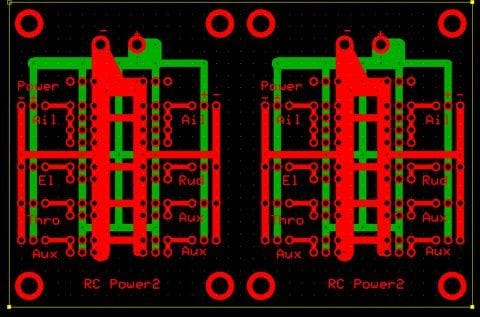
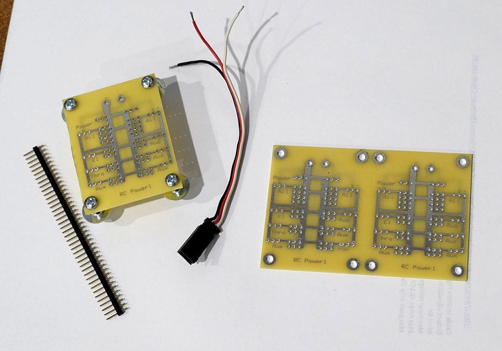
In the previous photos you can see how the circuits are 2 sided. You can draw traces on either. It's pretty easy to work with. I threw a copy of the PCB file here if anyone wants one already made up:
Index of /MSC
Index of /MSC
12-11-2022, 07:34 AM
#6
Forgot to add this:
HOWEVER, they have an option called “Standard Mini Board Plus”. If you can fit your circuit in 3.8" x 2.5" it cost $61 for 3. Doing so I was able to put 2 power board on each meaning I get 6 for this price; just cut with band saw. With friends this begins to be affordable.
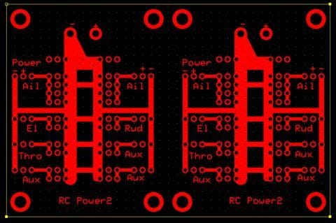
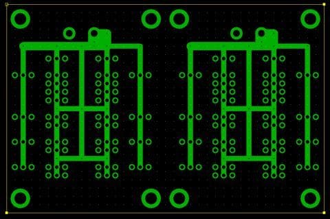
This is the circuit I built. Copper traces are 1.7 mil which . . . at .113” width gives you an acceptable continuous use of 6 amps. The boards I made are 2 sided so you can see how the current is widely distributed. There is more than enough trace to cover 6 amps.
You can use pins or solder in pigtails. PIns you can get at Jameco part #160882. I soldered male plugs to the board which go to the receiver. Then I soldered female plugs for the servo’s. The mounting holes fit 6-32 for mounting. You can see how you can use multiple servos. If this is not enough, you can use both circuits on one board. The circuit in photo is first gen. You can see from the drawings how the servo traces were beefed up even more.
For a battery source I use a 1100 3c pack with a Castle regulator from www.radicairc.com. It uses an EC3 plug good for 60 amps and 18ga wire. Max amps far more than I will need.
Just wanted to throw this out as an alternative.
HOWEVER, they have an option called “Standard Mini Board Plus”. If you can fit your circuit in 3.8" x 2.5" it cost $61 for 3. Doing so I was able to put 2 power board on each meaning I get 6 for this price; just cut with band saw. With friends this begins to be affordable.
This is the circuit I built. Copper traces are 1.7 mil which . . . at .113” width gives you an acceptable continuous use of 6 amps. The boards I made are 2 sided so you can see how the current is widely distributed. There is more than enough trace to cover 6 amps.
You can use pins or solder in pigtails. PIns you can get at Jameco part #160882. I soldered male plugs to the board which go to the receiver. Then I soldered female plugs for the servo’s. The mounting holes fit 6-32 for mounting. You can see how you can use multiple servos. If this is not enough, you can use both circuits on one board. The circuit in photo is first gen. You can see from the drawings how the servo traces were beefed up even more.
For a battery source I use a 1100 3c pack with a Castle regulator from www.radicairc.com. It uses an EC3 plug good for 60 amps and 18ga wire. Max amps far more than I will need.
Just wanted to throw this out as an alternative.

 12-12-2022, 06:11 AM
#9

Very nice design of your PDB. I hope you get lots of business!
I've used Express PCB and similar companies many times in the past, especially in the early days of my ESC business. Once I got to a high-enough volume I changed over to a local PCB production house to handle the board fab and SMT assembly. That saved a huge amount of time for me.
You need to talk about this on other forums like RCG, which have a much higher readership. Advertise!
Andy
12-12-2022, 06:33 AM
#10
Very nice design of your PDB. I hope you get lots of business!
I've used Express PCB and similar companies many times in the past, especially in the early days of my ESC business. Once I got to a high-enough volume I changed over to a local PCB production house to handle the board fab and SMT assembly. That saved a huge amount of time for me.
You need to talk about this on other forums like RCG, which have a much higher readership. Advertise!
Andy
I've used Express PCB and similar companies many times in the past, especially in the early days of my ESC business. Once I got to a high-enough volume I changed over to a local PCB production house to handle the board fab and SMT assembly. That saved a huge amount of time for me.
You need to talk about this on other forums like RCG, which have a much higher readership. Advertise!
Andy
Thanks
03-08-2023, 06:25 PM
#11
Senior Member
Join Date: Feb 2023
Location: Corryton, TN. Fly at Lucky Lane RC Club
Posts: 160
Likes: 0
Received 23 Likes
on
21 Posts
Your initial post said you were flying a large gasser Bearcat. Your loss of control was probably from low voltage as you suggested. I have a MX2 with a DLE 55RA engine on it that had the same problem when I bought it used. I too experienced repeated glitches, even with a Spektrum 9 channel receiver and three satellite receivers. I checked the ignition spark pug harness for proper grounding and verified it was fully seated on the spark plug. The ignition module was already located away from all servos and the receiver, the kill switch was a fiber optic isolated Rxcel unit, the throttle linkage was non-metallic, and the ignition was already on a separate LiFe battery. Then I placed a volt meter on the receiver plug and discovered there was a 2 volt power drop when all servos were operating, even under no load conditions. To fix the voltage drop, I installed a second 3000 mah LiFe flight battery, a second switch harness and larger gage power cables with Deans T connectors. Then I installed a Smart Fly power expander board with batt/safe and an optically isolated kill switch. Now there is no measurable voltage drop to the receiver under load. The Rx now receives buffered 5 volt power and my RF link is rock solid. Most flights' data logs show between 0 and 1 frame losses per 15 minute flight.
