


Scale military build (I hope)
 01-18-2021 | 08:53 PM
#26
Thread Starter

Well after almost a year I dusted it off again as time flies when you aren't in a rush, and used most your free time, and disposable income on other things that are more important.
Did some things like spread epoxy over the PLA to strengthen it, and smooth out some of the seams I still gotta sand it flat though. I also added a exhaust pipe I had from the Tamiya body I destroyed in the 1st iteration of the body.
I made a spur gear cover. I 3d printed a tire I found on a site,and hollowed out a chamber for the spur gear to completely hide it, and screwed it to the back of the cab.
The other week I also added a front bumper I made out of PETG this thing can REALLY flex as I made 2 failures as I misjudged the distance from the bumper mount to where I needed it. So out of curiosity I decided to see how far it could bend, and honestly it flexed so far there is no way in hell it can break on this thing.

Then I also saw someone with a similar idea, and what they used for the rear, but to make it work I had to convert to leaf springs, and as I knew nothing about leaf springs I ordered the 1st pair on amazon I found
I also added the rear blue piece to cover the end of the 2 pipes I used for a frame extender, and to give something for the leafs to screw into. The halfass spacers between the frame, and leaf springs were made by recycling one of the failed front bumpers I mentioned above. I also made a piece that actually goes over the link mount point on the axles to screw the leafs into. I decided to ditch the other 2 links that I had on the top of the rear axle as with the leafs springs, and the 2 lower links it is solid.
Moving to links I lost a LOT of articulation, and to be honest I'm not 100% sure I installed em right as I only found one guide online which used hardware that looked close to what I had in the pack I bought Then again I might just have to break em in.
Anyways the rear will probably be made in the next month or so, and when it gets warmer I'll have to sand it down, and paint it.
Did some things like spread epoxy over the PLA to strengthen it, and smooth out some of the seams I still gotta sand it flat though. I also added a exhaust pipe I had from the Tamiya body I destroyed in the 1st iteration of the body.
I made a spur gear cover. I 3d printed a tire I found on a site,and hollowed out a chamber for the spur gear to completely hide it, and screwed it to the back of the cab.
The other week I also added a front bumper I made out of PETG this thing can REALLY flex as I made 2 failures as I misjudged the distance from the bumper mount to where I needed it. So out of curiosity I decided to see how far it could bend, and honestly it flexed so far there is no way in hell it can break on this thing.
Then I also saw someone with a similar idea, and what they used for the rear, but to make it work I had to convert to leaf springs, and as I knew nothing about leaf springs I ordered the 1st pair on amazon I found
I also added the rear blue piece to cover the end of the 2 pipes I used for a frame extender, and to give something for the leafs to screw into. The halfass spacers between the frame, and leaf springs were made by recycling one of the failed front bumpers I mentioned above. I also made a piece that actually goes over the link mount point on the axles to screw the leafs into. I decided to ditch the other 2 links that I had on the top of the rear axle as with the leafs springs, and the 2 lower links it is solid.
Moving to links I lost a LOT of articulation, and to be honest I'm not 100% sure I installed em right as I only found one guide online which used hardware that looked close to what I had in the pack I bought Then again I might just have to break em in.
Anyways the rear will probably be made in the next month or so, and when it gets warmer I'll have to sand it down, and paint it.

The following users liked this post:
FREEDOM83 (08-29-2024)
08-17-2024 | 12:37 PM
#27
Thread Starter
Wee time flies 10 years since I started this project, and 3 since last update.
No its not dead nor forgotten(ok I did forget about it for 2 years or so )
)
ANYWAYS it has come a long way I actually started it up again as I was looking for a part, and it turned out I used it on this thing. Since I got interested in it again I found a good model of a deuce and a half which I used as a reference(mainly for proportions, and to see details I couldn't see in pictures) in the creation of the bed model I made. The model I made was done in tinker cad from scratch using primitive shapes. The rails are held on by 4 screws for the sides, and 3 for the front one so if I want I could make a covered top for it (which I plan to do eventually)
The bed is pretty much completely made it just needs the finishing work like sanding, and filling in spots where I joined the parts as I had to melt them together. I used a propane soldering iron on a low heat to join em. I tried glue, but it just wouldn't work due to not being able to have anything in the middle of the bed to join it due to it being too thin unlike how I have 2 dowels in the I beam sections per side.
I had to move the rear tires back as far as possible cause I was slightly off on my measurement, and the middle axle was just barely hitting the mudflap which wasn't bad as I measured it with a tape measure cause my calipers couldn't go that high. To do so I drilled new holes in the rails with the farthest back hole for the leaf springs being about 2mm's from the end of the rail. All of the holes were shifted over to match.
I also removed the top linkage mount point for the middle axle as honestly it didn't really do anything, I tested the motions pulling, pushing, etc of the axle before, and after, and noticed no difference. So I moved the lower linkage mount points to that location, and put them on the outside of the rail(they were binding on the inside). I lost one of the leaf spring front mounts so I designed, and printed 4 new ones as the original metal ones were kinda flimsy, and bending The rear where the shackle is at instead of just scrap material cut, and drilled I used washers, and a nut to get the proper distance. None of which can be seen due to the bed having rails that cover them.
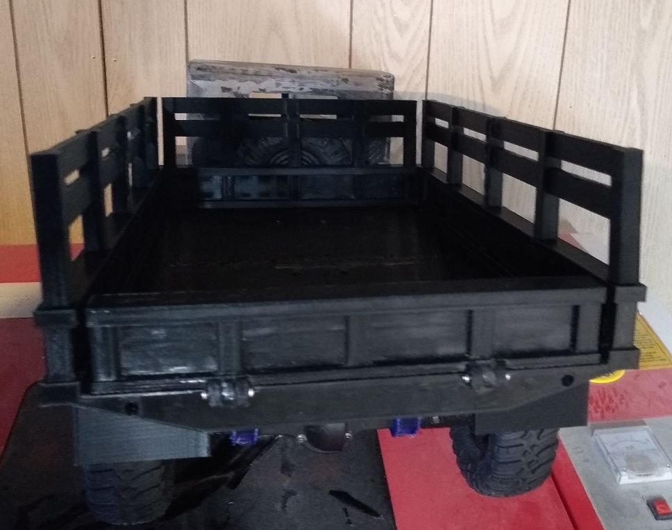
The tailgate can open and close. It was easier to do this then to print it in place as I would have had to add fake hinges for looks, and it cut down on the amount of waste plastic that would have been needed for supports..
I am going to redo the cab in 2 parts where as currently it was something like 9-10. I started printing it, but my printer ran out of filament when the back of the cab was like 95% done wasting a LOT of PLA+ So that is on hold for the immediate future)
I've also been thinking of adding in a light kit I have from another build I planned to do, but never did that adds working brake lights, turn signals, and headlights which the bed was designed for. Now if I go with the lights I'm also thinking of moving the battery to the bed of the truck, and drilling a hole in the bed to run power to it. I would make some scale crates that would be stacked up to cover the battery that are held in place with magnets to make the battery easy access as taking the cab on and off with wires running would be a major pain.. Only thing is if I do go the electronics route it will not be waterproof as it is right now, and can't be used in foul weather, or near water so there are tradeoffs(unless I make some kind of sealed box for the light controller).
No its not dead nor forgotten(ok I did forget about it for 2 years or so
)ANYWAYS it has come a long way I actually started it up again as I was looking for a part, and it turned out I used it on this thing. Since I got interested in it again I found a good model of a deuce and a half which I used as a reference(mainly for proportions, and to see details I couldn't see in pictures) in the creation of the bed model I made. The model I made was done in tinker cad from scratch using primitive shapes. The rails are held on by 4 screws for the sides, and 3 for the front one so if I want I could make a covered top for it (which I plan to do eventually)
The bed is pretty much completely made it just needs the finishing work like sanding, and filling in spots where I joined the parts as I had to melt them together. I used a propane soldering iron on a low heat to join em. I tried glue, but it just wouldn't work due to not being able to have anything in the middle of the bed to join it due to it being too thin unlike how I have 2 dowels in the I beam sections per side.
I had to move the rear tires back as far as possible cause I was slightly off on my measurement, and the middle axle was just barely hitting the mudflap which wasn't bad as I measured it with a tape measure cause my calipers couldn't go that high. To do so I drilled new holes in the rails with the farthest back hole for the leaf springs being about 2mm's from the end of the rail. All of the holes were shifted over to match.
I also removed the top linkage mount point for the middle axle as honestly it didn't really do anything, I tested the motions pulling, pushing, etc of the axle before, and after, and noticed no difference. So I moved the lower linkage mount points to that location, and put them on the outside of the rail(they were binding on the inside). I lost one of the leaf spring front mounts so I designed, and printed 4 new ones as the original metal ones were kinda flimsy, and bending The rear where the shackle is at instead of just scrap material cut, and drilled I used washers, and a nut to get the proper distance. None of which can be seen due to the bed having rails that cover them.
The tailgate can open and close. It was easier to do this then to print it in place as I would have had to add fake hinges for looks, and it cut down on the amount of waste plastic that would have been needed for supports..
I am going to redo the cab in 2 parts where as currently it was something like 9-10. I started printing it, but my printer ran out of filament when the back of the cab was like 95% done wasting a LOT of PLA+
So that is on hold for the immediate future)I've also been thinking of adding in a light kit I have from another build I planned to do, but never did that adds working brake lights, turn signals, and headlights which the bed was designed for. Now if I go with the lights I'm also thinking of moving the battery to the bed of the truck, and drilling a hole in the bed to run power to it. I would make some scale crates that would be stacked up to cover the battery that are held in place with magnets to make the battery easy access as taking the cab on and off with wires running would be a major pain.. Only thing is if I do go the electronics route it will not be waterproof as it is right now, and can't be used in foul weather, or near water so there are tradeoffs(unless I make some kind of sealed box for the light controller).
Last edited by SyCo_VeNoM; 08-17-2024 at 12:41 PM.
The following users liked this post:
FREEDOM83 (08-29-2024)
08-29-2024 | 01:10 PM
#28
Thread Starter
Well made new rear rail extensions
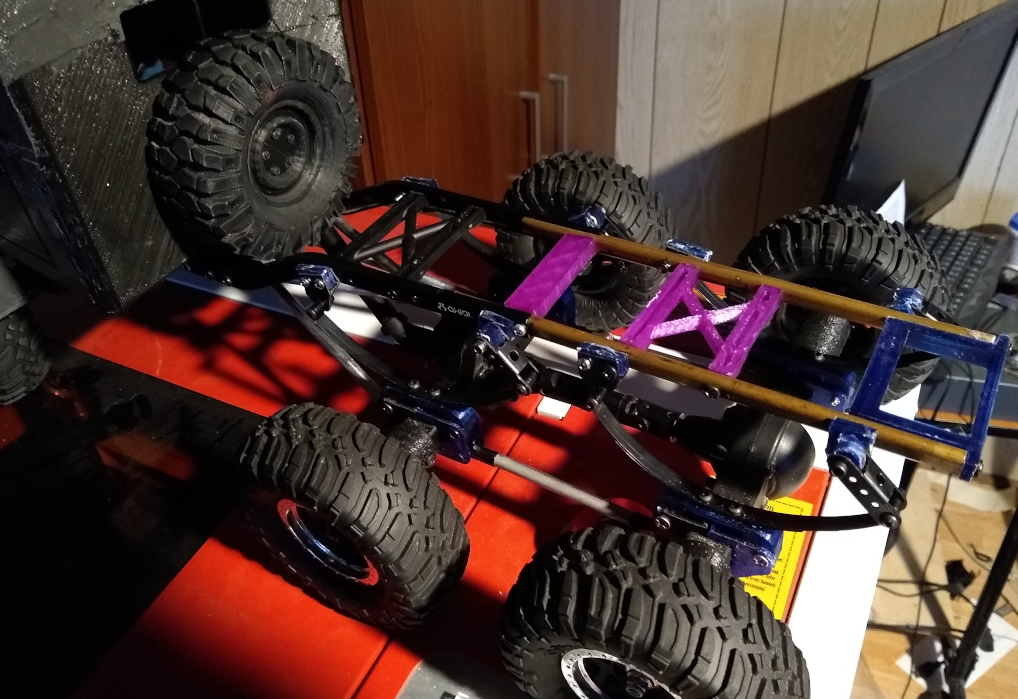
I found a piece of c-channel I salvaged out of a no-name broken food vacuum storage thing a few months back, and held it upto to an axial rail, and was shocked how well they fit together. So I cut it in half, and it was literally the PERFECT length to the point if it was 3mm's shorter it wouldn't have worked..
Anyways drilled holes in them. I drilled the one side, and then I took the other ,and just taped it together, and drilled through to mirror them perfectly
I decided to paint them black... but yea that was pointless as you can see in the pic below as the paint scratched up to high hell even, and didn't bond well in others. Might be cause the primer can was real old, or due to the extremely high humidity and temps, but not like it matters as it is completely covered anyways.
I had to redo all the chassis stiffeners, and even the leaf spring mounts as the c-rail is a bit wider then it was with the bronze tubing. But yea this also brings the leaf springs into alignment with the mounts on the axles where prior it was a little bowed.
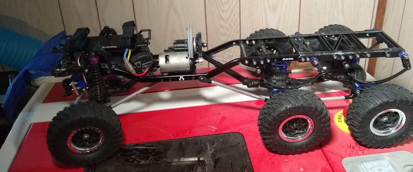
It is now really solid, and perfectly straight. The bronze tube wasn't perfectly straight, and it was crushed in at points a little bit, and would wiggle a bit back and forth so the wheels weren't' even perfectly straight. Also the holes on the bronze tubes I used weren't perfectly aligned with each other
Also the bed I made barely fits. I thought I might have to cut a bit of it up underneath, but its such a close with the screws that you can't even get a fingernail in between the screw of the leaf spring shackle, and the beds rail
I found a piece of c-channel I salvaged out of a no-name broken food vacuum storage thing a few months back, and held it upto to an axial rail, and was shocked how well they fit together. So I cut it in half, and it was literally the PERFECT length to the point if it was 3mm's shorter it wouldn't have worked..
Anyways drilled holes in them. I drilled the one side, and then I took the other ,and just taped it together, and drilled through to mirror them perfectly
I decided to paint them black... but yea that was pointless as you can see in the pic below as the paint scratched up to high hell even, and didn't bond well in others. Might be cause the primer can was real old, or due to the extremely high humidity and temps, but not like it matters as it is completely covered anyways.
I had to redo all the chassis stiffeners, and even the leaf spring mounts as the c-rail is a bit wider then it was with the bronze tubing. But yea this also brings the leaf springs into alignment with the mounts on the axles where prior it was a little bowed.
It is now really solid, and perfectly straight. The bronze tube wasn't perfectly straight, and it was crushed in at points a little bit, and would wiggle a bit back and forth so the wheels weren't' even perfectly straight. Also the holes on the bronze tubes I used weren't perfectly aligned with each other
Also the bed I made barely fits. I thought I might have to cut a bit of it up underneath, but its such a close with the screws that you can't even get a fingernail in between the screw of the leaf spring shackle, and the beds rail
The following users liked this post:
FREEDOM83 (08-29-2024)
11-07-2024 | 11:45 PM
#29
Thread Starter
well cab is basically done. I need to get some magnets for the hood as I decided to make a bracket, and screw the cab to the front bumper.
instead of being glued, and looking like crap like the old one I took all the parts that were scaled in the cad program, and assembled them so there were less parts to print, and assemble. I also modified them to screw together.
Basically the sides, front windows, rear, and roof are all one piece, the front grill is a separate piece, the front fenders are separate, and the hood. The fenders are held on with 5 screws each to make them secure, and the front grill screws into a bracket(4 screws from the front) that connects the 2 sides, and borrows 2 fender screws on each side to make it nice and rigid. The bracket that holds the front grill on I made it to screw into the front bumper mount, and drilled 2 holes in the bumper mount to make it nice and solid.


I made the turn signal bracket that screws to the front fenders they just aren't put on yet
I also have to find the front headlight parts I planned to use, and try to figure out where I put the exhaust pipe that screws on the cab side
The painting is going to have to wait until spring as its now too cold to paint around here.
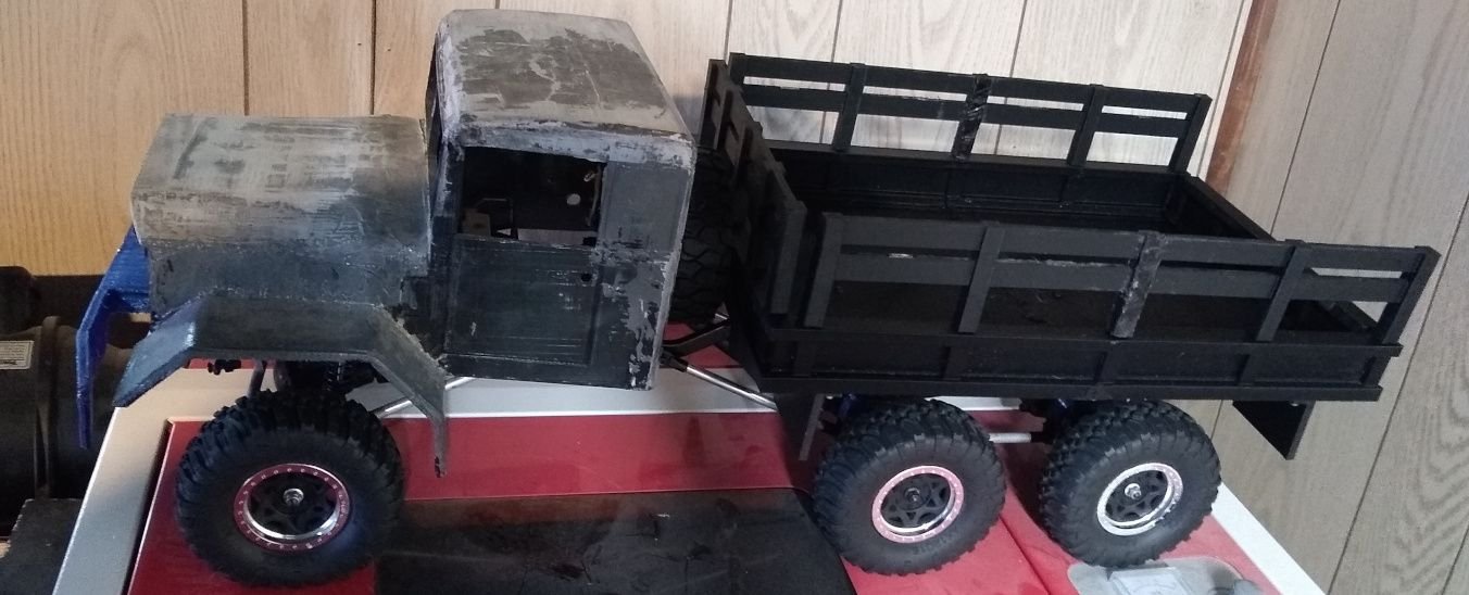
The vehicle in the bed of it is a 18th scale HPI Mini Recon showing how big this sucker is
Funny how I started it 10 years ago, and basically scrapped the majority of what I did in that time to redo a good chunk in the last 4 months >.>
Things to still do
1 Put the light buckets on the front Fenders. They are made(they were being printed when I took the pictures) which will be done probably tomorrow. There won't be an update pic as that is so minor it isn't worth it IMO.
2.Make some kind of bracket to mount where the tire is screwed int othe back of the cab that runs down to the frame to make the rear of the cabs mounting secure as right now it is not securely on in the back
3 find something to fit in the headlight area so I can pop some LEDs in it.
4 find the smoke stack, and put it on(I have a rough idea where I might have put it)
5 get some magnets to hold the front hood on, and glue them in place.
6. Paint it.
7. laser cut out some windows out of acrylic, and silicone em into place
8 (possibly)install LED kit I've had sitting around for ages that has working brake lights, and turn signals
9.(possibly) make accessories to fill in the large gap like a gas tank, a step, and a piece to slightly cover the spare tire like shown in the original picture I based it on. I would have to figure out how to securely attach it to the cab.
instead of being glued, and looking like crap like the old one I took all the parts that were scaled in the cad program, and assembled them so there were less parts to print, and assemble. I also modified them to screw together.
Basically the sides, front windows, rear, and roof are all one piece, the front grill is a separate piece, the front fenders are separate, and the hood. The fenders are held on with 5 screws each to make them secure, and the front grill screws into a bracket(4 screws from the front) that connects the 2 sides, and borrows 2 fender screws on each side to make it nice and rigid. The bracket that holds the front grill on I made it to screw into the front bumper mount, and drilled 2 holes in the bumper mount to make it nice and solid.
I made the turn signal bracket that screws to the front fenders they just aren't put on yet
I also have to find the front headlight parts I planned to use, and try to figure out where I put the exhaust pipe that screws on the cab side
The painting is going to have to wait until spring as its now too cold to paint around here.
The vehicle in the bed of it is a 18th scale HPI Mini Recon showing how big this sucker is
Funny how I started it 10 years ago, and basically scrapped the majority of what I did in that time to redo a good chunk in the last 4 months >.>
Things to still do
1 Put the light buckets on the front Fenders. They are made(they were being printed when I took the pictures) which will be done probably tomorrow. There won't be an update pic as that is so minor it isn't worth it IMO.
2.Make some kind of bracket to mount where the tire is screwed int othe back of the cab that runs down to the frame to make the rear of the cabs mounting secure as right now it is not securely on in the back
3 find something to fit in the headlight area so I can pop some LEDs in it.
4 find the smoke stack, and put it on(I have a rough idea where I might have put it)
5 get some magnets to hold the front hood on, and glue them in place.
6. Paint it.
7. laser cut out some windows out of acrylic, and silicone em into place
8 (possibly)install LED kit I've had sitting around for ages that has working brake lights, and turn signals
9.(possibly) make accessories to fill in the large gap like a gas tank, a step, and a piece to slightly cover the spare tire like shown in the original picture I based it on. I would have to figure out how to securely attach it to the cab.
Last edited by SyCo_VeNoM; 11-08-2024 at 12:06 AM.
01-17-2025 | 12:46 PM
#30
Thread Starter
WELL I went in a bit of a different direction with this
You can see I did do some of the checklist above
I struck 1, 2, 3, 4, 5, 7 off the list from the prior post as they are complete
The bracket for 2 also is a place to mount the gas tanks which I found that I had from a tamiya cab(the original attempt which I butchered for a cab over 10 years ago, and threw out it looked so bad)
for 7 I changed the material, and the way it was cutout. I used the top cover from a costco pie for the window material as it was nice, clear, and a large piece. So I used scissors to cut it, and hot glue to attach em.
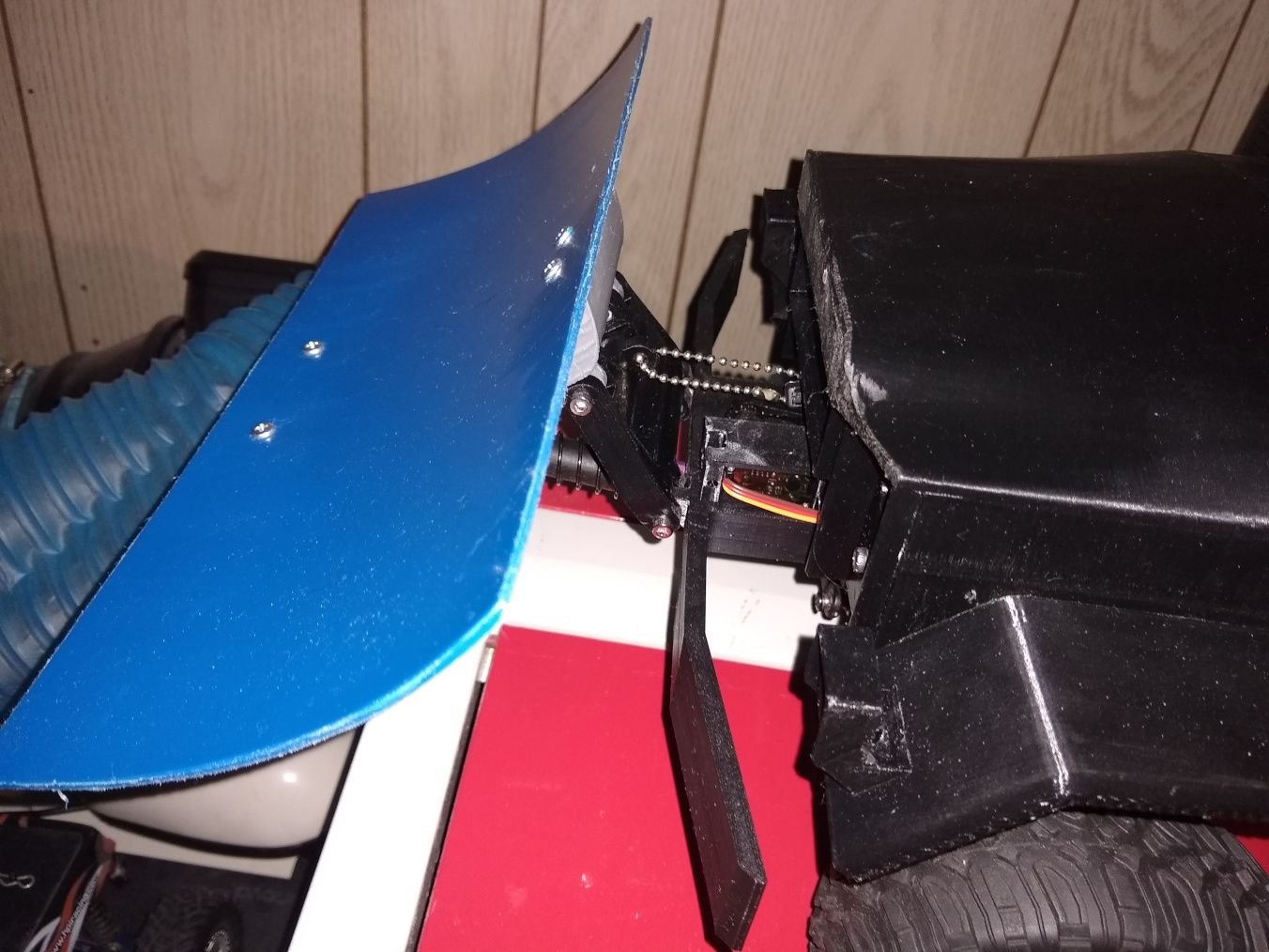
I made a new bumper with a mini servo mount that sort of looks like a winch in the spot a winch should go, and I put 3 mounting spots on the bumper for a snow plow, or other accessory. Snow plow attached currently.
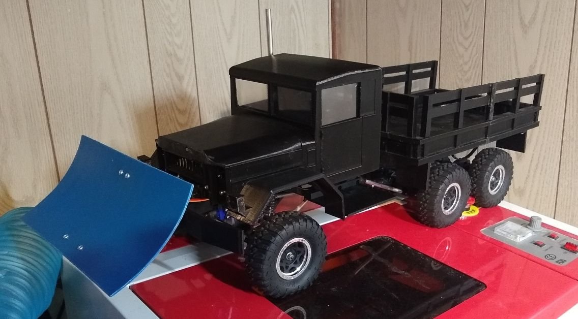
You can also see the bracket for mounting the back of the cab to the chassis in the bottom pic, and how I also had it make a shelf to mount things to like it was in the original picture.
You can see I did do some of the checklist above
I struck 1, 2, 3, 4, 5, 7 off the list from the prior post as they are complete
The bracket for 2 also is a place to mount the gas tanks which I found that I had from a tamiya cab(the original attempt which I butchered for a cab over 10 years ago, and threw out it looked so bad)
for 7 I changed the material, and the way it was cutout. I used the top cover from a costco pie for the window material as it was nice, clear, and a large piece. So I used scissors to cut it, and hot glue to attach em.
I made a new bumper with a mini servo mount that sort of looks like a winch in the spot a winch should go, and I put 3 mounting spots on the bumper for a snow plow, or other accessory. Snow plow attached currently.
You can also see the bracket for mounting the back of the cab to the chassis in the bottom pic, and how I also had it make a shelf to mount things to like it was in the original picture.
01-17-2025 | 12:58 PM
#31
Thread Starter
Here is the headlight I also made, and installed(after the above picture was taken)

It has a hole for an LED for when I get a new electric kit (I used to one mentioned prior in a Wrangler I made which pushed this project back a little)
I'm also soon going to test putting the battery in the bed with a box covering it that looks like a crate.
It has a hole for an LED for when I get a new electric kit (I used to one mentioned prior in a Wrangler I made which pushed this project back a little)
I'm also soon going to test putting the battery in the bed with a box covering it that looks like a crate.
01-18-2025 | 08:24 PM
#32
Thread Starter
Well here is the new tentative battery box
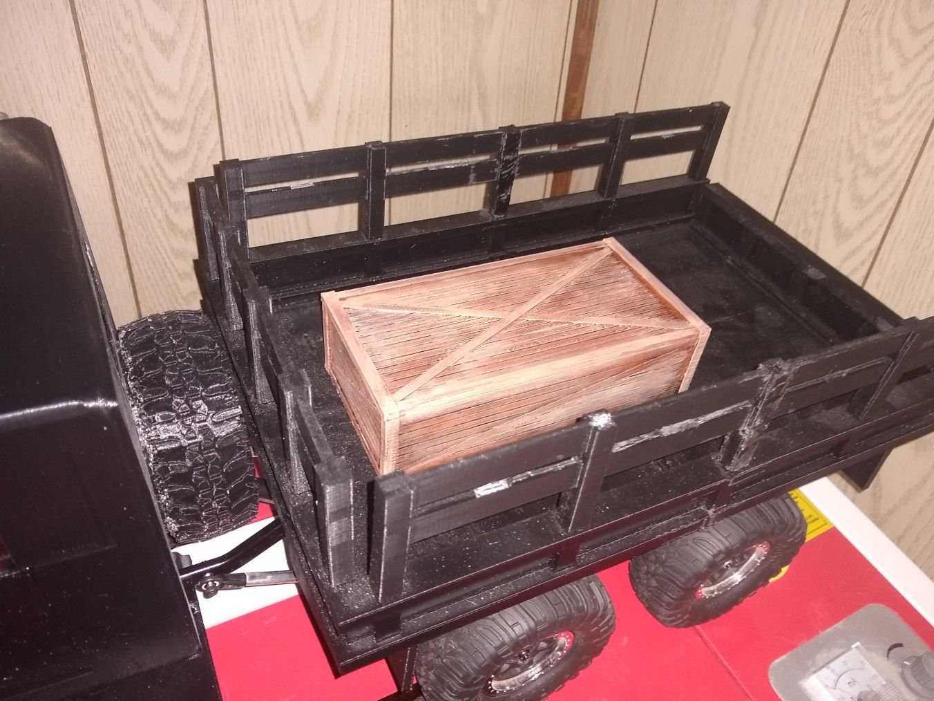
I kind of like how it looks will also solve another issue I am soon going to hit as to where to put the added electronics when I get them as I can put the electronics in the front where the battery tray currently is.
I kind of like how it looks will also solve another issue I am soon going to hit as to where to put the added electronics when I get them as I can put the electronics in the front where the battery tray currently is.
07-31-2025 | 10:11 PM
#34
Thread Starter
thanks I kinda stalled out on work on it, but plan on working on it again soon to finish it once and for all.
I am planning to redo the beds posts. I already designed the part just have to print it. I'm going to have the posts have actual wood slot in them to make it look a bit better as there won't be a joint line in the middle of center post..
I am planning to redo the beds posts. I already designed the part just have to print it. I'm going to have the posts have actual wood slot in them to make it look a bit better as there won't be a joint line in the middle of center post..
01-23-2026 | 01:12 PM
#35
Thread Starter
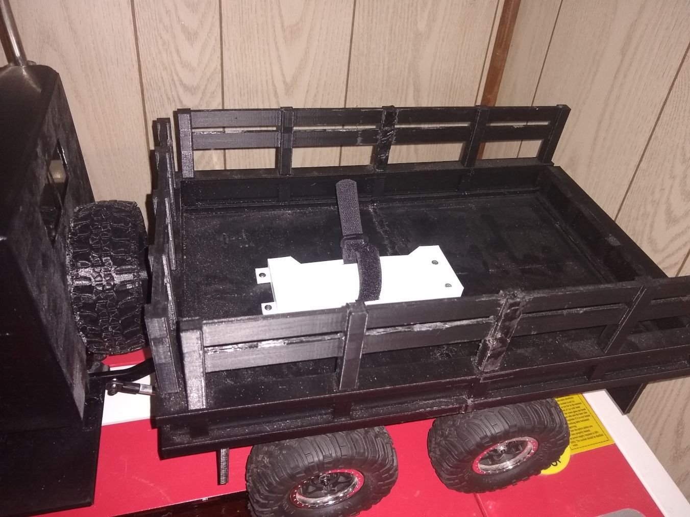
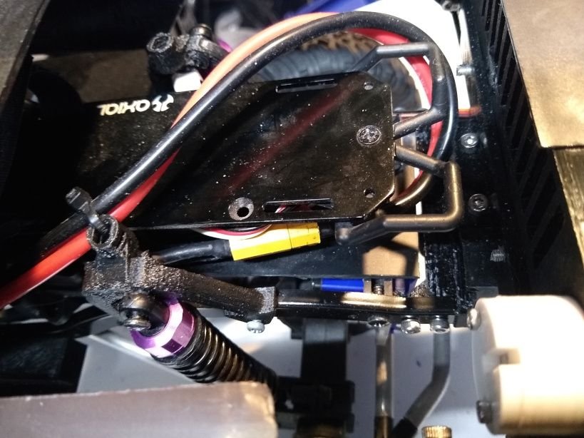
Well I got around to finalizing the battery in the bed
To start things off in the software I used to make everything I took the battery tray, and the box, lined them up, and took the negative. I also added 4 squares in the size of some neodymium magnets that I harvested from a broken outrunner brushless motor.I had.
I then cut out the opening for the wires

After that I removed a little material from where the magnets were going, and then I took one of the magnets from the bad motor heated it up (making it worthless), and used it to press into the spaces I made so the magnets will have a firm fit.
After that I ran the wire, and installed a 3d printed grommet to cover the slightly jagged hole I cut.

And no the tray is not crooked it is perfectly straight, and the battery is in the tray crooked.
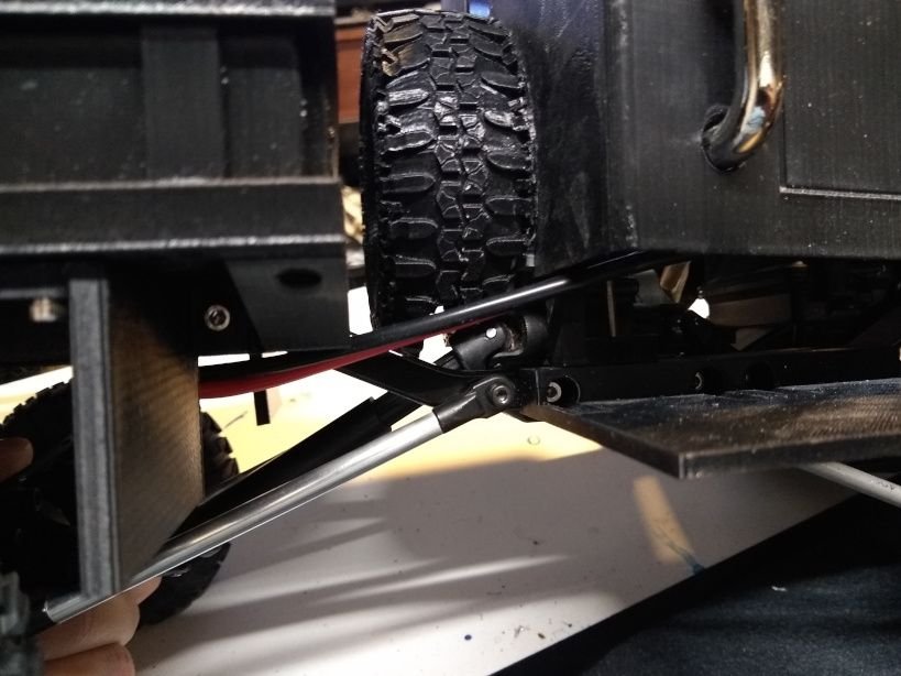
and to just show how it was ran as I zip tied the wire to the frame to keep it out of the way of the drive shafts.
I would take out the tray to put it possibly in my jeep build to replace the printed one, but I didn't feel like unscrewing the top, but when I eventually paint this, and have to disassemble it I do it then. I would have painted it last year, but stuff happened(air brush's valve breaking, stuff happening, and arthritis flareups), and when I finally had time, and the equipment to do so it was too cold already >.>
To start things off in the software I used to make everything I took the battery tray, and the box, lined them up, and took the negative. I also added 4 squares in the size of some neodymium magnets that I harvested from a broken outrunner brushless motor.I had.
I then cut out the opening for the wires
After that I removed a little material from where the magnets were going, and then I took one of the magnets from the bad motor heated it up (making it worthless), and used it to press into the spaces I made so the magnets will have a firm fit.
After that I ran the wire, and installed a 3d printed grommet to cover the slightly jagged hole I cut.
And no the tray is not crooked it is perfectly straight, and the battery is in the tray crooked.
and to just show how it was ran as I zip tied the wire to the frame to keep it out of the way of the drive shafts.
I would take out the tray to put it possibly in my jeep build to replace the printed one, but I didn't feel like unscrewing the top, but when I eventually paint this, and have to disassemble it I do it then. I would have painted it last year, but stuff happened(air brush's valve breaking, stuff happening, and arthritis flareups), and when I finally had time, and the equipment to do so it was too cold already >.>
Last edited by SyCo_VeNoM; 01-23-2026 at 01:15 PM.


