


HL-Tiger I: Missing lifting jack mount
 05-09-2013 | 11:53 PM
#1

Thread Starter
Senior Member
Joined: Sep 2010
Posts: 188
Likes: 0
Received 0 Likes
on
0 Posts
From: Luedenscheid, GERMANY
 HL-Tiger I: Missing lifting jack mount
Hi guys,
as you can see, the lifting jack of the Tiger does not have a mount. But it should have one, shouldn´t it?
Well, if there is none, we have to build one. And we will. After finishing, it will be working, too.

Here is what it should look like.

The next picture is an original picture of a Tiger lifting jack mount. Yours should look alike.

Ok, let the games begin.
Remove lifting jack. It is glued so you have to force it. Also remove leftovers.

Prepare the jack as shown.


Take poly plates or stripes. You need thickness 1 and 2mm.
For the first component you need to create two peaces as shown on the next picture.


For the second component you need a poly block 2x2x3mm.

Because this report was created by testing, some parts might show up different than yours. Next picture you´ll see. There should only be a small block without the thinner parts at the edges.

Next we need a poly tube, diameter inside 1mm, diameter outside 1,3-1,5mm. Everthing smaller should work, too. But it will be much more difficult to build.

To adjust the hinch parts, use a needle or a pin with the same diameter.

Cut off three slices from the tube, 1mm thick.

Glue two slices to the edges of component one, as shown. Make sure that the third slice fits between.

Glue the third slice centered to the 3mm edge of component two, as shown.

Assemble both components. You might need to do some rework on them to make them working. Then it should look like this:


Cut off another slice from the tube, 3mm thick.
Glue it centered to the opposite edge of component two. Then drill a 1mm hole centered to the tube wall.
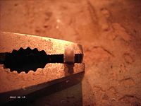
Take a small M1 screw and glue it into the hole. Leave a 1mm slit between the head of the screw and the tube wall. Why? You´ll see later.

Now we finished two of the needed components. They should look like this:

As you can see on the original picture, the single components are welded to another plate. This one we will prepare, now. Take a 3mm strip and glue the first components, with at least 20mm space between, to the strip as shown.


Then cut the strip 1mm underneath the components.

There are four parts on the picture, because I built two mounts. So don´t worry, you just need two parts.
And again, cut off three slices from the tube, 1mm thick.
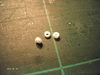
Still motivated? Or did you throw everything into the garbage, yet?
If not, let us continue.
Measure the distance between the center point of the left tube and upper edge of the right tube wall. In this case it is 6mm.

Glue two of the slices to the plate. The centerpoint of the tubes should be, in this case, 6mm away from the centerpoint of the tubes of component one. And make sure, that the third slice fits in between.

Cut the plate 1mm above the two tube slices. Don´t put the rest piece away. You need that one next..

Glue the third slice centered to the rest piece, twice, of course.

After the glue dried, we can do a little testing. Lets see if it works. Maybe you need to do some rework on this one, too.


At last you have to cut and slit the plate to fit the components edge and the screw.


Here you see the actual assembled peaces.

For fixing the mount we draw a reference line direktly to the mudguard mount.

Fix both mounts in a position the jack fits in without problems. You might try first a little bit before glueing the mount. Remember to leave some space to the exaust system. See the original picture to check out the two still missing parts. And also watch the position to the Feifels.


As a hinch pin we finaly use a 1mm poly pin. You also can use wire or something else, of course. Assemble the mount as shown.


The mount is now finished. We just have to add the two support brackets. Details see next picture.

I just prepared something.

Glue both brackets as shown. Make sure the jack touches all four support areas (the ones of the mount and the ones of the brackets).


On the last picture you see a metal jack from a supplier. So you can use different ones.
The only thing you have to add, if it is still missing, is a crank handle for the jack. That´s it.

Greetings
Birger
For a lot more help with your Heng Long Tiger I tank, follow the below link ...
<font size="+1">HL-TIGER I, Basics, Failures and how to remove them.</font>
as you can see, the lifting jack of the Tiger does not have a mount. But it should have one, shouldn´t it?
Well, if there is none, we have to build one. And we will. After finishing, it will be working, too.
Here is what it should look like.
The next picture is an original picture of a Tiger lifting jack mount. Yours should look alike.
Ok, let the games begin.
Remove lifting jack. It is glued so you have to force it. Also remove leftovers.
Prepare the jack as shown.
Take poly plates or stripes. You need thickness 1 and 2mm.
For the first component you need to create two peaces as shown on the next picture.
For the second component you need a poly block 2x2x3mm.
Because this report was created by testing, some parts might show up different than yours. Next picture you´ll see. There should only be a small block without the thinner parts at the edges.
Next we need a poly tube, diameter inside 1mm, diameter outside 1,3-1,5mm. Everthing smaller should work, too. But it will be much more difficult to build.
To adjust the hinch parts, use a needle or a pin with the same diameter.
Cut off three slices from the tube, 1mm thick.
Glue two slices to the edges of component one, as shown. Make sure that the third slice fits between.
Glue the third slice centered to the 3mm edge of component two, as shown.
Assemble both components. You might need to do some rework on them to make them working. Then it should look like this:
Cut off another slice from the tube, 3mm thick.
Glue it centered to the opposite edge of component two. Then drill a 1mm hole centered to the tube wall.
Take a small M1 screw and glue it into the hole. Leave a 1mm slit between the head of the screw and the tube wall. Why? You´ll see later.
Now we finished two of the needed components. They should look like this:
As you can see on the original picture, the single components are welded to another plate. This one we will prepare, now. Take a 3mm strip and glue the first components, with at least 20mm space between, to the strip as shown.
Then cut the strip 1mm underneath the components.
There are four parts on the picture, because I built two mounts. So don´t worry, you just need two parts.
And again, cut off three slices from the tube, 1mm thick.
Still motivated? Or did you throw everything into the garbage, yet?
If not, let us continue.
Measure the distance between the center point of the left tube and upper edge of the right tube wall. In this case it is 6mm.
Glue two of the slices to the plate. The centerpoint of the tubes should be, in this case, 6mm away from the centerpoint of the tubes of component one. And make sure, that the third slice fits in between.
Cut the plate 1mm above the two tube slices. Don´t put the rest piece away. You need that one next..
Glue the third slice centered to the rest piece, twice, of course.
After the glue dried, we can do a little testing. Lets see if it works. Maybe you need to do some rework on this one, too.
At last you have to cut and slit the plate to fit the components edge and the screw.
Here you see the actual assembled peaces.
For fixing the mount we draw a reference line direktly to the mudguard mount.
Fix both mounts in a position the jack fits in without problems. You might try first a little bit before glueing the mount. Remember to leave some space to the exaust system. See the original picture to check out the two still missing parts. And also watch the position to the Feifels.
As a hinch pin we finaly use a 1mm poly pin. You also can use wire or something else, of course. Assemble the mount as shown.
The mount is now finished. We just have to add the two support brackets. Details see next picture.
I just prepared something.
Glue both brackets as shown. Make sure the jack touches all four support areas (the ones of the mount and the ones of the brackets).
On the last picture you see a metal jack from a supplier. So you can use different ones.
The only thing you have to add, if it is still missing, is a crank handle for the jack. That´s it.
Greetings
Birger
For a lot more help with your Heng Long Tiger I tank, follow the below link ...
<font size="+1">HL-TIGER I, Basics, Failures and how to remove them.</font>


