


Next tank build, assistance needed
 04-18-2014, 10:30 AM
#76
Senior Member
Thread Starter
Join Date: May 2007
Location: Orlando, FL
Posts: 121
Likes: 0
Received 0 Likes
on
0 Posts
All right, the build has started and will be part of a build thread that I will be starting soon.
I do have two questions about the Bosch headlights that I bought. I e-mailed ETO a few days ago, but they have responded, so I thought I would ask here to see if anyone can help.
1. The covers for the lights have two protrusions on them. There is a matching indentation on the light for the top protrusion, but not the bottom one. Should I file out the area at the bottom of the light, where the cover protrusion would fit, or is there a better way to take care of this?
2. There are two hex nuts included with the lights. I am assuming they re to secure the light to the tank. The threaded stud hanging off the bottom of the light has a non-threaded part at the bottom. Do I cut this part off, or am I totally on the wrong track.
I received my warm white chip LEDs and they are exactly what I was looking for. The color is right, and they are small enough to fit inside the lights. I am now waiting for a Pololu RC switch to come in, so I can finish up the circuit that will allow the LEDs to be powered off the receiver and be switchable from and extra channel on my transmitter. This part of the build is a long way off, but I love messing with electronics, so I could not resist.
On a related note, I ordered some of the pico size LEDs to maybe re-work the rear lights on my LEO, and man are these things small. They may be too small, but that is another project for another time.
Steve
 04-18-2014, 12:37 PM
#77
Don't file anything off! These are finished and ready to go. The light slit is to be horizontally mounted.
The non-threaded part is for the wiring conduit.
Should look similar to this:

Jeff
The non-threaded part is for the wiring conduit.
Should look similar to this:
Jeff
Last edited by Panther F; 04-18-2014 at 12:41 PM.
04-18-2014, 08:20 PM
#78
Senior Member
Thread Starter
Join Date: May 2007
Location: Orlando, FL
Posts: 121
Likes: 0
Received 0 Likes
on
0 Posts
Jeff - first of all, that is a great picture. I love the mount and the tubing. I hope mine turns out half as good as yours. Are your light(s) functioning? If so, how did you run the wires?
Now, back to my questions, which I apparently botched horribly, as my points did not come across. Let me try again, with pictures this time.
1. The covers for the lights have two protrusions on them. There is a matching indentation on the light for the top protrusion, but not the bottom one. Should I file out the area at the bottom of the light, where the cover protrusion would fit, or is there a better way to take care of this?
 This shows the two protrusions on the headlight cover
 You may not be able to see it to well (for now), but there is a matching recess in the area circled at number 1. This recess does not exist at number 2, so the headlight cover will not sit flush on the headlight.
2. There are two hex nuts included with the lights. I am assuming they are to secure the light to the tank. The threaded stud hanging off the bottom of the light has a non-threaded part at the bottom. Do I cut this part off, or am I totally on the wrong track. Area 3 above shows what I am referring to. There is a non-threaded part that is circled and makes it impossible to put on the nut. Should this part be cut off, and if so, what is the best way to do so without destroying the threads? Will I need a die to restore the threads when I am done?
I don't know how to make the pictures bigger. If someone could let me know, I will adjust the size to make them easier to see. I see if I click on the image it is a thumbnail that opens the full size image. Is there a way to insert images inline, like you did, without having them on the Web somewhere?
Thanks again for the help,
Steve
Now, back to my questions, which I apparently botched horribly, as my points did not come across. Let me try again, with pictures this time.
1. The covers for the lights have two protrusions on them. There is a matching indentation on the light for the top protrusion, but not the bottom one. Should I file out the area at the bottom of the light, where the cover protrusion would fit, or is there a better way to take care of this?
2. There are two hex nuts included with the lights. I am assuming they are to secure the light to the tank. The threaded stud hanging off the bottom of the light has a non-threaded part at the bottom. Do I cut this part off, or am I totally on the wrong track. Area 3 above shows what I am referring to. There is a non-threaded part that is circled and makes it impossible to put on the nut. Should this part be cut off, and if so, what is the best way to do so without destroying the threads? Will I need a die to restore the threads when I am done?
I don't know how to make the pictures bigger. If someone could let me know, I will adjust the size to make them easier to see. I see if I click on the image it is a thumbnail that opens the full size image. Is there a way to insert images inline, like you did, without having them on the Web somewhere?
Thanks again for the help,
Steve
Last edited by metalhead1986; 04-18-2014 at 08:28 PM.
04-19-2014, 03:41 AM
#79
Oh (ha ha) that is not my project but just an image I used from the Internet.
I would say to contact who you purchased it from as I would THINK there shouldn't be any modifying of those parts. It does look like the threaded stud is raw and unfinished (the nut fastener cannot start on it) and you are completely right... those parts should line up.
Hope this helps and you get a simple answer!
Jeff
Last edited by Panther F; 04-19-2014 at 03:47 AM.
04-19-2014, 05:28 AM
#80
After looking at your photos, I have these same lights. I would cut the portion of non-threaded material off so you can thread the provided nut. As for the missing recess, you have two choices, file or cut off the bottom protrusion or file/cut a recess. I plan on wiring mine for SMD LED's so I want to be able to open them if the LED's need to be replaced. I plan on using lock-tite or white elmers glue to hold the cover to the light in place. Either of these should keep the cover in place during normal use. So for me I plan to file/cut the 2nd recess so the glue will have more to bite and hold onto. Hope this helps.
Last edited by MAUS45; 04-19-2014 at 04:28 PM.
04-19-2014, 09:32 AM
#81
Senior Member
Thread Starter
Join Date: May 2007
Location: Orlando, FL
Posts: 121
Likes: 0
Received 0 Likes
on
0 Posts
Thank you Maus.
Your suggestions are exactly the way I was leaning. It's good to hear from someone that has them already.
Thanks for the tips on securing the covers. I also will be placing SMD LEDs in mine, but failed to take into account what would happen if/when the LEDs burned out. Although, with LEDs driven properly, they should last hundreds of hours, at least.
I received my Pololu RC switches today, so I can breadboard the whole thing and make sure it will work the way I want it to.
Steve
04-19-2014, 01:25 PM
#82
Oh good! I am glad you have a positive solution to your problem and questions. I was about to suggest the same thing but not having the parts in my hands I was a little hesitant on doing it that way.
Looks like you're on your way now! Good luck and show us some pics of it when you're finished!
Jeff
Looks like you're on your way now!
Good luck and show us some pics of it when you're finished!Jeff
04-19-2014, 05:40 PM
#83
Senior Member
Thread Starter
Join Date: May 2007
Location: Orlando, FL
Posts: 121
Likes: 0
Received 0 Likes
on
0 Posts
Thanks for the encouragement Jeff.
I am taking pictures as I go and will start some sort of build thread soon. All these small parts gave me the excuse to get the close up lenses I have been wanting for my D600 and to build a totally redneck (I hope that term is OK here) macro ring lite. Focusing with the close up lenses is manual only and will present a challenge, but it will be just another skill I master with this build.
Steve
04-22-2014, 05:19 AM
#84
Senior Member
Thread Starter
Join Date: May 2007
Location: Orlando, FL
Posts: 121
Likes: 0
Received 0 Likes
on
0 Posts
Now that the build has started and lots of bits are on the bench for mods and upgrades, I really should decide on a tank to model this after.
Since I don't have any sort of attachment to any period, battle, or tank, my decision is going to be based on a couple of arbitrary requirements.
1. It must be painted dunkelgelb. I don't know what it is, but I have become almost obsessed with the discussions/controversy surrounding this seemingly innocent color.
2. The tank must be pre July 1943 major changes. I like the early commander's cupola and hatch, but most of all, I want to use both of the Bosch lights I have.
I am still on the fence about camouflage. I may be willing to tackle it, but I really do like the look of an all dunkelgelb Tiger.
Does anyone have any recommendations of particular tanks that fit my requirements? I have had a hard time finding much information on colors, etc. of specific tanks, and the Jentz book does not get into that part of the Tiger, from what I can tell (I have gone through all the pictures, but have left the text for later.
I found many sites with Tiger information, but are there any that are the gold-standard when researching this type of material?
Lastly (for now), I wanted to get some input on what people here are using when painting dunkelgelb? I plan on getting a number of manufacturers products to test and see what I like best (Vallejo, AK, Ammo by Mig, and maybe Tamiya). From my reading, I know this is a very subjective thing, but the more information I have, the better.
Thanks again for all the help and information,
Steve
04-22-2014, 05:43 AM
#85

Steve, do be wary about using Dunkelgelb, It was not introduced into service with the German armed forces until October 1942 and only as a base colour at that time, it was used more freely after February 1943. Try this reference. www.miniatures.de/colour-ral-farben.html
Last edited by jarndice; 04-22-2014 at 05:48 AM.
04-22-2014, 05:47 AM
#86
As for Dunkelgelb? It is and forever will be debated as a color in the model world? Not sure why but it always seems to be the color that is debated the most.
For me, I use an airbrush and shoot Tamiya XF-59 Desert Yellow mixed 50/50 with either Tamiya XF-60 Dark Yellow or Tamiya XF-2 White. Tamiya XF-60 Dark Yellow has a green tinge to it so that is why I use the Desert Yellow or White to take the green tinge down. Personally I think it is all in the eyes of the beholder. I plan on trying AK's Dark Yellow primer on my next paint job as a base color. Just want to get away from the Tamiya chemicals. If you do try Tamiya spray in a well ventilated room as it is not good to breath even though it is water based. Check this site for colors used by Chris Wauchop on his Panther G, JagdPanther Mid, and JagdPanzer IV l/70. I used his Dark Yellow mixes to get the color I wanted. Just need to get the same thing in a safer to breath paint.
http://www.missing-lynx.com/gallery/...glatecw_1.html
http://www.missing-lynx.com/gallery/...ermidcw_1.html
http://www.missing-lynx.com/gallery/...l70cwcw_1.html
Last edited by MAUS45; 04-22-2014 at 05:52 AM.
04-22-2014, 08:12 AM
#87

Don't freak out over Dunkel, with scale effect, weather, grime, it really doesn't matter. According to Jentz, who'd I'd trust as the authority, it's greenish yellow, so Vallejo or Tamiya fit the bill well.
Bottom line is, after factory base coat (which varied), camo, etc was wildly different based on method and solvent. The paint was sent to staging as a concentrate and would be thinned with whatever was on hand at the time.
Add to that actual lighting. In my shop, I have fluorescent, tungsten, halogen, incandescent and LED lighting. For painting I have color corrected daylight bulbs. Dunkelgelb is completely different under all of them. Some it's a ghastly green, some it's sandy.
I was with Jentz at an AMPs show once (for some reason, our tables are usually near each other) when a few guys got him to head over to the exhibition tables to look at their work. He went down the row explaining what was wrong with each one, it was like he stormed into a kindergarten class and told every kid there was no Santa. I thought these guys were going to end up in tears.
Model paint companies do a fair amount of research, you'll be happy either way.
04-22-2014, 08:56 AM
#88
Senior Member
Thread Starter
Join Date: May 2007
Location: Orlando, FL
Posts: 121
Likes: 0
Received 0 Likes
on
0 Posts
Thanks for the info guys. This is why I am looking for a source of illustrations or descriptions at least of various tanks and their color schemes. Are there any good sources for this information?
I know all about Tamiya paint. I used it on my Leo, and the old school way of painting I used (on the sprue) used a lot of it. I have since seen the light on painting the assembled base model and am going to do that with the Tiger.
I have also read that there is a greenish tint to the dunkelgelb, and that Vallejo makes a couple of colors (middleton and green ochre I believe) that are pretty good out of the bottle. I also plan on using their dark yellow primer. I just want to try a few brands to see which one I like best.
I have read about the base color being mixed with gasoline, old oil, etc. by the guys in the field, so I am sure variations in the color were endless.
I also have many types of lighting in my shop, so I only use the color corrected lamp I have to judge what colors should look like. The rest of the lights are used as work lights, etc. The makeshift macro light I made uses white LED strips that I bought for my quadcopter, and the color temperature of them is not one my camera has a setting for. I found myself having to use the Kelvin while balance setting on my camera to get close. I still need to fine tune this one, so my pictures don't come out too yellow or too blue.
I feel for those guys that wanted to show Jentz their work, only to have him tear it down, bit by bit. I be they never do that again. I am not looking for that level of detail. I want something that is as close to accurate as I am able to get, and that makes me happy and proud of the work I put into it.
In case it gets lost in the ramblings above, if anyone knows of any sources of accurate illustrations or descriptions of colors worn by specific tanks, please let me know. My eyes are Googled out.
Steve
04-22-2014, 09:47 AM
#89
Ausf, I agree, Dunkelgelb should have a slight tinge of green maybe just not as much as Tamiya's XF-60. Like you said depending on the thinner used and if it was painted in the field or in the factory all things considered it could be several shades to green or not so green. I had the chance to see the Stug III G at Fort Knox before it was shipped off to Fort Benning GA to the new tank training school and for me it seems to be a good example of what the war time colors could have looked like. It is still in it's original paint, which is still in good shape other then having been worn off by people climbing all over it before they stopped the allow people doing that. Me included!! It was also kept indoors away from sunlight as well. Anyway, one of the volunteers that help with the restorations took some photos of it outside as it was wating to be moved to it's new home at Benning. I have attached one as an example of what the colors may have looked like. Trust me it is not the defining color match, just an example. What is interesting is that the red oxide is showing through so it gives us a better idea of how dark the camo red brown could be. notice how the colors on the wheels have faded or oxidized? I wish they had not allowed people to climb and walk all over it as the paint would have been in even better shape!!! I plan on doing my Stug III G to represent this vehicle.
04-22-2014, 10:11 AM
#90
Keep in mind, if you buy them, you'll now have two thick volumes of hundreds of tanks you'll be hard pressed to pick one.
04-30-2014, 06:04 AM
#91
Senior Member
Thread Starter
Join Date: May 2007
Location: Orlando, FL
Posts: 121
Likes: 0
Received 0 Likes
on
0 Posts
OK, I am back. Lots going on and little time for updates, so here we go.
I have finally decided on a tank to model after. I am going to build 250251. The reason I went for this tank is that it fits the bill for all features I want (built mid-April through May 1943), and there is a great line drawing in the Jentz book. My problem now is that I cannot find what tank the unit was sent to and what number it became. Does anyone have this information or know of someplace where I can find out. Maybe I am the only weirdo who picks things like this, but I think a resource that give all this information would be great (if it is not already out there).
The other thing I have been working on the last few nights is photo etch. I picked up the early clamps and clasps set to practice on, since this is my first real experience with photo etch (the Leo 2A6 PE parts don't really count). I have to say that anyone who really likes working with photo etch may have a few screws loose, and this is 1/16th scale. I cannot even imaging 1/48 or 1/72.. Wow, this is not what I expected. I am sure it is my newbieness and my less than skinny fingers, but successfully working with photo etch takes some mad skills. After three nights work, I have completed one full clasp, one almost full clasp, and parts for one clamp. Bending the parts is easy. It's when you add in wire and fitting little parts to other little parts with this wire, etc. where madness comes in. My partial clamp looks pretty awesome, but soldering the tiny wires and fitting the clasp into the mount without mangling it beyond recognition deserves a medal. I am seriously thinking about whether or not I want to go further with PE on the Tiger. I know if I practice a lot more and get tips and tricks from people, I could eventually manage to do a pretty good job. I just don't know if I want to put the Tiger on hold for that long. Oh, decisions, decisions.
I'll try and get a picture up of my progress so far, so you can see what I have managed so far.
My last bit of progress has been getting the tank to the point of having tracks mounted. I skipped all the work on the rear, pending my decision on PE parts. Adding the bearings to the wheels was not that difficult using a technique I read about in another thread where the person used a sleeve over the drill bit used to drill out the wheels as a stop. Measurements need to be precise, but once set up, the process is super simple and takes no time at all with the soft plastic of the wheels. The idlers were another story altogether. I do not have the tools necessary to successfully deepen the hole to allow clearance for the bearing's depth, so I used the bushing on the idlers. I tried, but the drill bit just started digging into the metal. Maybe if I get the proper tool at some point I will come back and drill them out for bearings, but for now I am satisfied.
Speaking of tracks, the manual says to remove three links from the track before installing. When I removed three links, no matter how far I adjusted the idlers, the tracks would never meet. I ended up removing just one link. This is where I could get the tracks to sit just right without having the idler adjuster too far one way or the other. Is this OK, or have I maybe done something horribly wrong here? Did I maybe not build something in the idler adjuster mechanism right?
I am not a huge fan of the system used to adjust the idlers. It may be the best option out there, but I just don't like the way it works. What would be great would be a system where you could adjust the idlers using the holes made for this purpose, like on the full scale tank. That would eliminate the unsightly screws protruding from the bottom of the tank and make adjusting the idlers a task that does not require putting the tank on its side or some good skills to adjust the screws with the tank perched on the end of a table. Too bad I am not a mechanical engineer.
Steve
05-01-2014, 06:47 PM
#92
Senior Member
Thread Starter
Join Date: May 2007
Location: Orlando, FL
Posts: 121
Likes: 0
Received 0 Likes
on
0 Posts
Back to something that was discussed earlier, the Bosch headlights. I worked on them a week or so ago. Here is what I did.
For the mounting screw, I grabbed my Dremel (cordless model) and a grinding wheel. I then began slowly grinding away the non-threaded part of the mounting post right up to where the threads start. Once that was done, I put the nut in a nut driver to hold it secure and slowly screwed the headlight into the nut. I was pretty surprised at how easy it was to get the screw started. Once on the threaded post, I unscrewed it and screwed it back on a few times. After a couple of times, the nut screwed on very easily. The second one was a little less successful, as my control of the grinding wheel was a little less precise, and ground up into the threads a little on one side. I thought I was in big trouble, but the nut went on with only a little more difficulty. After a few times on and off, it to is easy to screw on.
Next, I grabbed my corded Dremel, as it has higher speeds and the smallest cutting bit I had. I took a file and marked where the indentation needed to be for the lower protrusion of the headlight cover and carefully went to work on making a slot for that protrusion to fit into. After some careful cutting and stopping often to check the fit, I now have a cover that fits the headlight. The slot is a little wider than the top one. If I had a narrower cutting bit, the slot would have been much more precise, but as it is the slot works fine.
Here is what it looks like after the grinding and cutting jobs.

And here is how the cover fits now.

Looks pretty good to me.
Steve
For the mounting screw, I grabbed my Dremel (cordless model) and a grinding wheel. I then began slowly grinding away the non-threaded part of the mounting post right up to where the threads start. Once that was done, I put the nut in a nut driver to hold it secure and slowly screwed the headlight into the nut. I was pretty surprised at how easy it was to get the screw started. Once on the threaded post, I unscrewed it and screwed it back on a few times. After a couple of times, the nut screwed on very easily. The second one was a little less successful, as my control of the grinding wheel was a little less precise, and ground up into the threads a little on one side. I thought I was in big trouble, but the nut went on with only a little more difficulty. After a few times on and off, it to is easy to screw on.
Next, I grabbed my corded Dremel, as it has higher speeds and the smallest cutting bit I had. I took a file and marked where the indentation needed to be for the lower protrusion of the headlight cover and carefully went to work on making a slot for that protrusion to fit into. After some careful cutting and stopping often to check the fit, I now have a cover that fits the headlight. The slot is a little wider than the top one. If I had a narrower cutting bit, the slot would have been much more precise, but as it is the slot works fine.
Here is what it looks like after the grinding and cutting jobs.
And here is how the cover fits now.
Looks pretty good to me.
Steve
05-01-2014, 07:56 PM
#94

Steve,
About the Tiger you are building, unless Jentz or someone has a picture of that particular tank with divisional markings on it you may never find out where it went. There are some pictures of Tigers with the hull number visible on the hull or on the gun muzzle cover. You may want to try to go at it from the other direction, by finding a tank with the same configuration in a known unit. I didn't see if anyone had posted the link to one of the great resources on the Tiger 1 Tiger in Focus http://www.tiif.de/ You will want to use Google translate unless you read German.They have quite a number of specific Tiger tanks listed in their forums with photos of most.
ETO armor has a two different idler adjusters for the Tiger 1 one from Daryl Turner and the other from Henntec the DT type spring loads the idler, so the tension is adjusted on the fly automatically. Henntec does offer the through the rear hull idler adjuster (like the real tank) but apparently not for the Tiger 1, they do offer it for the Panther and the King Tiger tanks, I suppose you might be able to adapt one of those to the Tiger 1 but maybe not. I think if it was possible they would have offered that type for the Tiger 1 as well.
Good Luck on your build. The picture is from the Tigers in Combat Volume 1 which I highly recommend as a reference source.

Steve
About the Tiger you are building, unless Jentz or someone has a picture of that particular tank with divisional markings on it you may never find out where it went. There are some pictures of Tigers with the hull number visible on the hull or on the gun muzzle cover. You may want to try to go at it from the other direction, by finding a tank with the same configuration in a known unit. I didn't see if anyone had posted the link to one of the great resources on the Tiger 1 Tiger in Focus http://www.tiif.de/ You will want to use Google translate unless you read German.They have quite a number of specific Tiger tanks listed in their forums with photos of most.
ETO armor has a two different idler adjusters for the Tiger 1 one from Daryl Turner and the other from Henntec the DT type spring loads the idler, so the tension is adjusted on the fly automatically. Henntec does offer the through the rear hull idler adjuster (like the real tank) but apparently not for the Tiger 1, they do offer it for the Panther and the King Tiger tanks, I suppose you might be able to adapt one of those to the Tiger 1 but maybe not. I think if it was possible they would have offered that type for the Tiger 1 as well.
Good Luck on your build. The picture is from the Tigers in Combat Volume 1 which I highly recommend as a reference source.
Steve
Last edited by Shark27; 05-01-2014 at 08:01 PM.
05-01-2014, 11:01 PM
#95
Hi Steve, If you are interested in building a Tiger 1 from the North African campaign, I would recommend going to - Tiger 1.info
and when you are on the page just click on any Tank no for all the information including photograph's, it only cover's Tiger's of Abteilung 501 but it is very useful. shaun
and when you are on the page just click on any Tank no for all the information including photograph's, it only cover's Tiger's of Abteilung 501 but it is very useful. shaun
05-02-2014, 05:32 AM
#96
Senior Member
Thread Starter
Join Date: May 2007
Location: Orlando, FL
Posts: 121
Likes: 0
Received 0 Likes
on
0 Posts
Thanks for the words or encouragement (or not ) Steve. I found what I was looking for an a whole lot more after looking on www.tiif.de. There is a gentleman on there that compiled a document of Tigers by Fahrgestell number and what unit they went to.Obviously, I don't know how accurate all the information in the document is, but it certainly appears he put a great deal of effort into the research for this document. Where appropriate, he listed his sources, including the source for 250251. It ended up as Tiger tactical number A02, 9th company, III Abteilung, Panzer-Grenadier, Division Gro�deutschland.
Searching for Tiger A02 even got me to a color rendering of its color scheme, seen here:
http://www.fprado.com/armorsite/tiger1_in_action.htm
Now, I just need to find more information about Tiger A02 and pictures, if possible, so I can continue with the build.
From the illustration on the page listed above, can someone tell me what the color is that is painted over the base color for the camo pattern? It looks maybe like it was olivgrun, but I want to be sure.
Thanks for all the assistance so far. This community is a wealth on information. Thanks so much.
Steve
) Steve. I found what I was looking for an a whole lot more after looking on www.tiif.de. There is a gentleman on there that compiled a document of Tigers by Fahrgestell number and what unit they went to.Obviously, I don't know how accurate all the information in the document is, but it certainly appears he put a great deal of effort into the research for this document. Where appropriate, he listed his sources, including the source for 250251. It ended up as Tiger tactical number A02, 9th company, III Abteilung, Panzer-Grenadier, Division Gro�deutschland.Searching for Tiger A02 even got me to a color rendering of its color scheme, seen here:
http://www.fprado.com/armorsite/tiger1_in_action.htm
Now, I just need to find more information about Tiger A02 and pictures, if possible, so I can continue with the build.
From the illustration on the page listed above, can someone tell me what the color is that is painted over the base color for the camo pattern? It looks maybe like it was olivgrun, but I want to be sure.
Thanks for all the assistance so far. This community is a wealth on information. Thanks so much.
Steve
05-02-2014, 05:53 AM
#97
Senior Member
Thread Starter
Join Date: May 2007
Location: Orlando, FL
Posts: 121
Likes: 0
Received 0 Likes
on
0 Posts
Steve - I have looked at both the Daryl Turner idler adjuster and the HennTec one. You are right. The Henntec appears to adjust from outside the hull, behind the idler wheel on the Tiger. that would be OK, too, as it still gets rid of the adjustment screws sticking out the bottom of the lower hull.
The Daryl Turner one looks very promising, as it has no adjustment screws at all, so it would be very clean. Also, I have heard it works very well. It is a little pricey, but I want to do this right, so a few extra bucks can be tolerated.
Steve
The Daryl Turner one looks very promising, as it has no adjustment screws at all, so it would be very clean. Also, I have heard it works very well. It is a little pricey, but I want to do this right, so a few extra bucks can be tolerated.
Steve
05-02-2014, 05:56 AM
#98
Senior Member
Thread Starter
Join Date: May 2007
Location: Orlando, FL
Posts: 121
Likes: 0
Received 0 Likes
on
0 Posts
Thanks for the link Jarndice. I thought I wanted to model a North African Tiger, but 250251 looks to have been on the Eastern front. I will keep that site bookmarked, in case another Tiger (maybe a modded HL at some point) is ever on the table.
Steve
Steve
05-02-2014, 08:23 PM
#99
Senior Member
Thread Starter
Join Date: May 2007
Location: Orlando, FL
Posts: 121
Likes: 0
Received 0 Likes
on
0 Posts
Now that I have my Tiger identified, and I have put aside the idea of flush mounting the screws on the bottom for now (technical difficulties were encountered that can be overcome at some point), I am going to turn my attention to the next area of the build that will probably be severely scaled back or eliminated altogether, and that is photo etch details.
As I have said above, I have not really worked with photo etch before, and this Tiger photo etch detail is far more complicated than I anticipated. I completely underestimated the size and complexity of the pieces and assemblies. After the three nights I have worked on it, here is the one complete clasp I have. Please excuse the lack of sharpness. I am still leaning how to use my close-up lenses, and my Photokit Sharpener plug-in broke, so I have not applied any sharpening here.

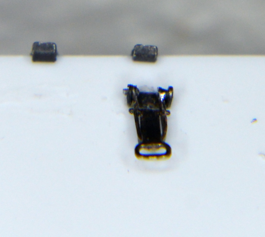


So, it is pretty awful, right? It is complete and it works but it certainly does not look great.
I don't want to hold up the build too long waiting for my skills to improve here, but there are definitely some photo etch assemblies I would like to have on the Tiger. I will live if they don't happen, but it would be nice to have them.
So, lay it on me. Should I press on without the photo etch, from what I made on my first outing, or can I maybe be successful with some of the basic photo etch kit for the Tiger with some more practice?
Thanks for any opinions,
Steve
As I have said above, I have not really worked with photo etch before, and this Tiger photo etch detail is far more complicated than I anticipated. I completely underestimated the size and complexity of the pieces and assemblies. After the three nights I have worked on it, here is the one complete clasp I have. Please excuse the lack of sharpness. I am still leaning how to use my close-up lenses, and my Photokit Sharpener plug-in broke, so I have not applied any sharpening here.
So, it is pretty awful, right? It is complete and it works but it certainly does not look great.
I don't want to hold up the build too long waiting for my skills to improve here, but there are definitely some photo etch assemblies I would like to have on the Tiger. I will live if they don't happen, but it would be nice to have them.
So, lay it on me. Should I press on without the photo etch, from what I made on my first outing, or can I maybe be successful with some of the basic photo etch kit for the Tiger with some more practice?
Thanks for any opinions,
Steve
05-03-2014, 03:51 AM
#100
Keeping in mind that macro photos are great for identifying flaws you'll never see otherwise, I wouldn't be too discouraged by that clip.
You can take a file to the sides and remove the protrusions and even things out. Even as is, especially turret bin clasps and tool clamps are infinitely more convincing than the molded on piece.
You can take a file to the sides and remove the protrusions and even things out. Even as is, especially turret bin clasps and tool clamps are infinitely more convincing than the molded on piece.