


Easy Antenna Modification
 10-09-2007 | 12:18 PM
#1

Thread Starter
Senior Member
Joined: Aug 2007
Posts: 1,439
Likes: 0
Received 0 Likes
on
0 Posts
From: Cardiff,
ON, CANADA
Want to eliminate the long out of scale antenna that comes with the HL RC tanks? Well after talking to my brother the "HAM" nut he said why not just replace the antenna with an internal antenna and proceeded to explain to me how to do it. Here's what he said " just measure the section of antenna you want to replce then cut a section of laquered copper wire like you would find in a choke or coil from an old radio or power supply the same length as the anteena that comes with the tank. So I tried what he said and "HOT DAM!" worked like a charm. I place the tank at one end of the house and tested it out works perfectly. I could start and stop the tank activate the machine gun, the cannon fire drive train responded as it should. I paced off the distance from the tank to the transmitter and was 20 good paces which would be approximately 60ft. Here is how I did it:
1. I measured the antenna and it measured 13-1/16"
2. I cut a section of the laquered wire to that length
3 I took a piece of 1/4" hollow styrene tubeing 1-5/8" long drill a tiny hole near the one end.
4. I inserted the one end of the copper insulated wire into the hole and brought the end out of the end of the tube approximately 1/4-3/8".
5. I then wound the wire around the tubeing and secured the other end to the tubeing with some cyano
6. I then glued short standoff's on either end feeding the end of the wire through the one end
7. When the glue had dried I then un-soldered the antenna wire where it is soldered to the anntena stub keeping the 2 sections of black wire.
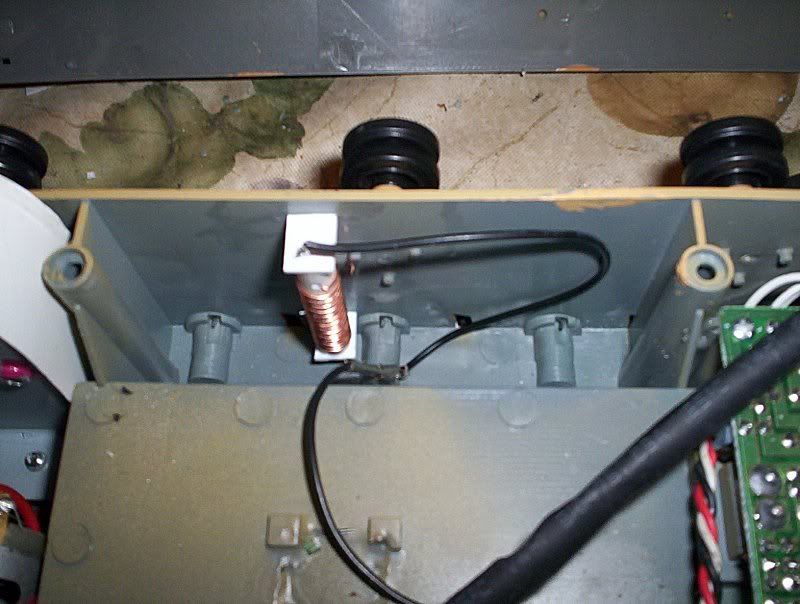
8. I then soldered the end of the black antenna wire to the end of the coil and tack glued it to the right inside panel of the hull.
Then I was test time... and it passed with flying colors.
Here are pics of the modification:
Pic 1 This shows the coil I used to get the laquered wire from I took the coil out of an old AT computer power supply. This pic shows the top view of the coil

Pic 2 side view of the same coil

Pic 3 Coil instslled in the HL PzrIII L
1. I measured the antenna and it measured 13-1/16"
2. I cut a section of the laquered wire to that length
3 I took a piece of 1/4" hollow styrene tubeing 1-5/8" long drill a tiny hole near the one end.
4. I inserted the one end of the copper insulated wire into the hole and brought the end out of the end of the tube approximately 1/4-3/8".
5. I then wound the wire around the tubeing and secured the other end to the tubeing with some cyano
6. I then glued short standoff's on either end feeding the end of the wire through the one end
7. When the glue had dried I then un-soldered the antenna wire where it is soldered to the anntena stub keeping the 2 sections of black wire.
8. I then soldered the end of the black antenna wire to the end of the coil and tack glued it to the right inside panel of the hull.
Then I was test time... and it passed with flying colors.
Here are pics of the modification:
Pic 1 This shows the coil I used to get the laquered wire from I took the coil out of an old AT computer power supply. This pic shows the top view of the coil
Pic 2 side view of the same coil
Pic 3 Coil instslled in the HL PzrIII L
 10-09-2007 | 12:37 PM
#3
Thread Starter
Senior Member
Joined: Aug 2007
Posts: 1,439
Likes: 0
Received 0 Likes
on
0 Posts
From: Cardiff,
ON, CANADA
Well according to my brother if you get that range now you should still get that range since the receiver see's the the antenna as it was. It is still the same length as before.
Since nothing is done that can't be un-done with a simple desolder and resolder back to the old antenna mount you have nothing to loose so simple to make give it a try. You could even run the end of the black wire out one of the vents and just lay the ciol on the back deck for a test if you like the results then mount internaly and make a scale dummy antenna on the outside.
You could also make a functioning external scale antenna by removeing the the amount of the scale antenna from the coil and put the coil between the black antenna wire and the end of the scale antenna as far as the receiver is concerned the antenna is still full length
10-09-2007 | 02:04 PM
#4
Senior Member
Pzr,
Cool idea. Nice sounding execution (I could not seem to download your pictures).
Ask your brother "Since we are dealing with the recvr only antenna, why match the wire lengths? Wouldn't a longer wire (to a point) give possibility of a greater recv range?" As long as you keep the internal loop seperated, or shielded, from the motors...
Splat
10-09-2007 | 03:56 PM
#5


Joined: May 2006
Posts: 540
Likes: 0
Received 0 Likes
on
0 Posts
From: los angeles,
CA
dang, if this does go the distance, i might have to do it since I wanted to detail my panzer and that stock antenna kinda kills the realistic effect. (i've only taken mine about 50 yards, that far away was hard to control since I can't see it as well)
10-09-2007 | 04:45 PM
#6
Thread Starter
Senior Member
Joined: Aug 2007
Posts: 1,439
Likes: 0
Received 0 Likes
on
0 Posts
From: Cardiff,
ON, CANADA
Receivers use a tunned antenna either fm or am. For those old enough remember when you bought the am/fm/cassette player for your car to replace the factory cheapo radio the instructuions told you to tune the radio to the loudest station at the high end of the dial then adjust the screw inside the cassette door what you were doing was tunning the antenna. with FM the antennas are all the same pretunned length. If the antenna is too long it's just as bad or worse than if too short. Antenna's are tunned to the frequency bandwidth. Now you can get even better tunning if you put a tuneable coil in series with the antenna coil and fine tune it to the exact tunned frequecy but that also has drawbacks will depend on the distance you fine tune to you may loose responce closer or further than the distance you tunned to.
But I will ask him about making the coil length longer just to be sure
But I will ask him about making the coil length longer just to be sure
10-09-2007 | 06:17 PM
#7

It's been a long time since I've done electronics but if I remember right then then the best antenna would be equal to the wave length of the signal recieved, so a 27mhz signal has a wavelength of approx 11m
Now you can't have a 11m antenna on your RC tank so the best you can do is go for a fraction of that 1/2, 1/4, 1/8, 1/16 or 1/32 which'll be 34.375cm, so you could have a 17cm antenna with a 17.375cm coil inside the tank.
If you want to find out the wavelength of your transmitter then go [link=http://www.sengpielaudio.com/calculator-wavelength.htm]HERE[/link] type in the frequency of your transmitter into section 2. "Radio and light waves in a vacuum" Rember that transmitters are in Mhz so 27Mhz is 27,000,000hz.
This'll give you an approx figure (unless some of you live in a vacuum) as air density will shortens wavelength.
10-10-2007 | 08:17 AM
#8

Great idea pzwest, its also been a while for me but I do remember that radiation in the radio spectrum propagates as a wave and antenna need to be tuned to a frequency for best reception. Dusting off this knowledge I see winding it up as shortening the antenna, now we will move into radio wave theory 
10-10-2007 | 09:24 AM
#9

Senior Member
Joined: May 2006
Posts: 728
Likes: 0
Received 0 Likes
on
0 Posts
From: Barcelona, SPAIN
Winding the Rx antenna is an old aeromodelling trick, but results are sort of unpredictable because of the many factors involved (servo installation, wiring, etc..)
Here you'll find a well documented article about lenghtening/shortening Rx antennae:
http://www.rc-cam.com/ant_exp.htm
Anyway this should become critic only in airplane rc, in our tanks we hardly need more than an effective 20-30m range (around 60'-90') and you can easily reach this range with virtually any lenght and type of Rx antenna
Cheers
10-10-2007 | 10:24 AM
#10
Senior Member
Pzr,
Sorry to bust your bubble, but in your scenario, what you were doing was tuning one of the tank circuits (L/C resonance, not Armor) to adjust an oscillator frequency. Transmitters need balanced antenna load, not receivers. You unbalance a transmitter back end and at best you loose output ppower, at worst, you blow the output stages. That's why you use quarter-wave and half-wave antennas for your CB, but your car radio would still work if you busted the telescoping antenna and plugged in a chunk of coat hanger, or why you could hook up one of those old crystal sets to a barbed wire fence and hear radio New York from Kansas (or East Texas). And why you can use a 36" s-dipole, or a 48" s-dipole, on an FM broadcast receiver with equal results, as long as you use 300 ohm feed line to make the dipole.
Splat
10-10-2007 | 10:56 AM
#11
Thread Starter
Senior Member
Joined: Aug 2007
Posts: 1,439
Likes: 0
Received 0 Likes
on
0 Posts
From: Cardiff,
ON, CANADA
Well I did a distance test with the antenna modification and started at 50yrds started the tank and tried all the functions. The kept adding 5 yrds to the distance with clear line of sight and repeated the sequence again. I Kept adding 5 yrds to the tests and stopped at 100yrds and everything still functioned. I figured at 100 yrds is ample distance because the tank would be hard to see if it was camo'ed and not on concrete but grass or sand terrain . I am satisfied this mod will work for any distance I plan to run it
10-10-2007 | 12:52 PM
#12
Senior Member
Pzr,
Congrats on making it out to 100 yds! I agree, that's as far away from my tank as I would want to get in the field. As I can not seem to get your pic.s downloaded, could you 1) state the length of your coil form and the approx. distance between loops, 2) tell where you mounted the new antenna in the hull?
Thanks and good going,
Splat
10-10-2007 | 06:04 PM
#13
Thread Starter
Senior Member
Joined: Aug 2007
Posts: 1,439
Likes: 0
Received 0 Likes
on
0 Posts
From: Cardiff,
ON, CANADA
Here are the links to my pics on my photobucket;
http://i2.photobucket.com/albums/y18...enna-mod01.jpg
Pic 2 side view of the same coil. coil length is 1-5/8" long and 1/4" diameter
http://i2.photobucket.com/albums/y18...enna-mod02.jpg
Pic 3 Coil installed in the HL PzrIII L
http://i2.photobucket.com/albums/y18...enna-mod03.jpg
http://i2.photobucket.com/albums/y18...enna-mod01.jpg
Pic 2 side view of the same coil. coil length is 1-5/8" long and 1/4" diameter
http://i2.photobucket.com/albums/y18...enna-mod02.jpg
Pic 3 Coil installed in the HL PzrIII L
http://i2.photobucket.com/albums/y18...enna-mod03.jpg
10-10-2007 | 06:21 PM
#14
Member
Joined: Sep 2007
Posts: 67
Likes: 0
Received 0 Likes
on
0 Posts
From: Bangalow, NSW,
AA, AUSTRALIA
PZRWEST , So simple and easy to do, congrats on being first to come up with it. This will become a standard thing to do. you should have it put in the sticky bit of the forum. Now to make the turret rotate 360 cause theres no silly antenna !!
10-10-2007 | 06:43 PM
#15
Thread Starter
Senior Member
Joined: Aug 2007
Posts: 1,439
Likes: 0
Received 0 Likes
on
0 Posts
From: Cardiff,
ON, CANADA
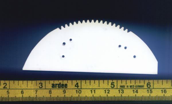
Here's how I solved the 360+ degree rotation. I made a pattern of the teeth on the turret ring gear and then cut new teeth in the ring gear where the tab was to stop the turret from rotateing any further. Now my turret can keep on rotateing till I either stop it or it twists the wires off. I re-made a quick movie with my Kodak Easy Share digital camera not the best for shooting video but you can see the turret in action. And the turret motor does have enough strength to bend the antenna over since I moved it to the correct location. In the pic of the template I included a section of tape measure to show the actual size of the pattern
Pattern
Modified Turret Ring Gear

Turret in motion
http://s2.photobucket.com/albums/y18...t=rotating.flv
I will be doing this modification to my PzrIII L as well... Nice to fool the other guy into thinking you can only rotate the turret so far when he sneaks up behind you and you rotate and whammo you nail him
Pattern
Modified Turret Ring Gear
Turret in motion
http://s2.photobucket.com/albums/y18...t=rotating.flv
I will be doing this modification to my PzrIII L as well... Nice to fool the other guy into thinking you can only rotate the turret so far when he sneaks up behind you and you rotate and whammo you nail him
10-10-2007 | 06:47 PM
#16
Thread Starter
Senior Member
Joined: Aug 2007
Posts: 1,439
Likes: 0
Received 0 Likes
on
0 Posts
From: Cardiff,
ON, CANADA
Maybe we should have a section just for modifications like mantel flipping, or other usefull mods. Could call it hints & tips or Tutorials or How To's
10-10-2007 | 10:14 PM
#19

Senior Member
Evergreen Metal Siding, .100" or .125", cannot remember right now and K&S Copper Soft Foil, .005" thick cut with a paper cutter. You can scale it for as many wires you want to run into the turret to a point. I set mine up for 5 but don't always use them.
10-11-2007 | 03:47 AM
#20
Member
Joined: Sep 2007
Posts: 67
Likes: 0
Received 0 Likes
on
0 Posts
From: Bangalow, NSW,
AA, AUSTRALIA
Swathdriver have you seen the three ring solder wire fix for turret rotation, its fixed to the geared turret rotation gear. It is a simple idea, similar in some ways to what you have done
10-11-2007 | 08:04 AM
#23
Senior Member
Pzr,
Can't get to photoBucket either (blocked site where I work, have to try it from home,,,oops, I didn't say that I was checking the forum while on company time....... I er, uh, well, Doh!).
Thanks for the data. As to your stickey question, What about Richard L's FAQs? Wouldn't be particularly easy to find without using the Search function, but as Swathie says "Search is your friend".
Thanks again and good going. Nice mod!
10-11-2007 | 03:07 PM
#24
Senior Member
Great idea pz.
I never thought of that at all.
I did it with model tug I built some years ago.I made a wooden frame and just wrapped the reciever wire around it,made a bed for it to fit into and away we went.
It went 60-70 yards across the lake with out any problems at all.
Miggers
I never thought of that at all.
I did it with model tug I built some years ago.I made a wooden frame and just wrapped the reciever wire around it,made a bed for it to fit into and away we went.
It went 60-70 yards across the lake with out any problems at all.
Miggers
10-11-2007 | 10:11 PM
#25
Thread Starter
Senior Member
Joined: Aug 2007
Posts: 1,439
Likes: 0
Received 0 Likes
on
0 Posts
From: Cardiff,
ON, CANADA
Here is a posting from another forum reguarding the antenna modification:
"heavyaslead ...Grand idea!
Just tried it with my 75MHz receiver, and I must say it does work very well, range was improved by almost 2X
Now I will fine-tune it for CH90 which will make a coil about 13 feet in length.
Also as a side note, my initial test also proved to cut down on the interference (since the entire antenna helical coil can be located away from motors and electronics or other metal parts)."

