


CARF F4U-1 Corsair build thread
 02-16-2016, 09:40 PM
#3201


Good news on the gear door inner detail. The new molds are going to the vacu-former this week. Should have them available in just a few more days. They will be installed on the Corsairs in the shop so you can see how they look.
We are also working on a resin antenna for the Corsair.

We are also working on a resin antenna for the Corsair.
Last edited by ram3500-RCU; 02-16-2016 at 09:43 PM.
 02-17-2016, 11:20 AM
#3203


Good news on the gear door inner detail. The new molds are going to the vacu-former this week. Should have them available in just a few more days. They will be installed on the Corsairs in the shop so you can see how they look.
We are also working on a resin antenna for the Corsair.
We are also working on a resin antenna for the Corsair.

 02-17-2016, 11:20 PM
#3205
Been working on these for some time. I think they will be popular for new builds and should be a fairly simple addition to flying models. Weight is almost nothing. This simple detail adds a lot of realism.
Still working on the mold for the antenna. Plan to make these two piece as we do with all our wood ones. This way it is removable for easier transport.
More detail items planned include the tail hook, break discs (Joe graciously sent me his molds for these so I could continue his work with them), and tie down hooks (these would be a great subject for a 3D printer but alas, I don't have one). The prototype leather strut boots are being installed on our in-house builds and will be available when final parts are reproduced and our cost is finalized.
cheers,
Gary
02-18-2016, 10:10 PM
#3206
Here are some pictures of our new strut cover boots. These were leather on the full scale and then just painted with the rest of the aircraft. We will do the same thing. The cap screws you see are only temporary. We will use buttons or flush on the final install.


Last edited by ram3500-RCU; 02-18-2016 at 10:13 PM.
02-18-2016, 11:08 PM
#3207
This video shows our new covers installed and working. You will see that it is slightly wider and longer because of the simplified method we are using to mount the strut cover. It does not pull itself in behind the leading edge for this reason.
www.youtube.com/watch?v=CxmCDmcxR1Y
www.youtube.com/watch?v=CxmCDmcxR1Y
Last edited by ram3500-RCU; 02-25-2016 at 09:18 AM.
02-19-2016, 04:11 AM
#3208
Here is a video to help with installing the strut cover gear door. This can be tedious as the gap around the door is small. This method helps you get the holes drilled perfectly so the door sits centered in the opening.
www.youtube.com/watch?v=F-fyelHjFhs
www.youtube.com/watch?v=F-fyelHjFhs
Last edited by ram3500-RCU; 02-25-2016 at 09:20 AM.
02-19-2016, 04:52 AM
#3211

Hello Corsair Owners,
Can someone point me into the right direction in regards to electrical landing gear conversion? I also heard that sierra is now offering electrical versions of their corsair gear? A friend of mine is planning on building a corsair with electric gears. How much $ is the current conversion from Down and Locked and also, is it possible to convert it without sending the gear in?
Thanks
T
02-19-2016, 05:06 AM
#3212
Hello Corsair Owners,
Can someone point me into the right direction in regards to electrical landing gear conversion? I also heard that sierra is now offering electrical versions of their corsair gear? A friend of mine is planning on building a corsair with electric gears. How much $ is the current conversion from Down and Locked and also, is it possible to convert it without sending the gear in?
Thanks
T
Can someone point me into the right direction in regards to electrical landing gear conversion? I also heard that sierra is now offering electrical versions of their corsair gear? A friend of mine is planning on building a corsair with electric gears. How much $ is the current conversion from Down and Locked and also, is it possible to convert it without sending the gear in?
Thanks
T
http://www.downandlocked.com/
Mitch is the pioneer in this for giant scale and still far and away the best IMO. Others have tried to copy what he does by sending his work to China for knock-off (Robart), but it isn't the same obviously.
PM me for more help with this if you like. DO NOT GO THROUGH CARF for the conversion. They will simply send it to Mitch and then mark it up (a lot).
Yes, the gear must be sent in, but NOT the wheels. That saves you some weight in shipping. In the conversion, some welding is done.
Cost is better discussed with Mitch directly. Mitch Stott 828 817-0412.
Again, PM me. I have something I can do for you.
 02-19-2016, 08:18 PM
#3214
On the Corsair gear, I have shared my thoughts on this before based on our experience with this model. Bears repeating. The Corsair gear scissors have only a fraction of cam over when down. This is because if it were more, they would not come unlocked. Air pressure is critical to hold them locked as mechanical lock is very weak. A good hit on landing like a slightly tail high touch down can unlock these gear. With the electric jack screw conversion, they CAN NOT come unlocked unless those screws turn. Really "Down and Locked". More conventional gear may be fine using air, but for Corsair gear, electric is the way to go IMO.

Last edited by ram3500-RCU; 02-25-2016 at 09:21 AM.
02-21-2016, 01:47 PM
#3215
Some pictures of the strut cover being installed.


After holes are piloted, we attach the boot to the strut cover.


Gear is lowered to account for some stretch. Then the retainer is screwed to the leading edge.


The cut out is oversize so that the cut behind the leading edge can be narrower. The door never needs to go through the surface with this method, even though being hard mounted.
After holes are piloted, we attach the boot to the strut cover.
Gear is lowered to account for some stretch. Then the retainer is screwed to the leading edge.
The cut out is oversize so that the cut behind the leading edge can be narrower. The door never needs to go through the surface with this method, even though being hard mounted.
Last edited by ram3500-RCU; 02-25-2016 at 09:24 AM.
02-27-2016, 06:49 AM
#3216
You may recall that one of the Corsairs we are working on was started by another builder. It is the full kit version. It MUST be emphasized that this version requires a very high degree of precision in building. I know it is less expensive, but it is not easy to get right if you have little experience with this type of building. Most of the operations you only get one chance at.
So we come to this. Just about everything this builder touched he screwed up. Hours have been spent undoing what he did. Both on the wings and fuselage. Some things just had to be replaced, like the elevators. He had decided to use two servos on them and cut the CF torque rod in two. OK, but then he glued them into the elevators!!! This meant that you could no longer separate them from the stabs for painting, and once the tiller was installed on the inside, nothing could be removed!!! NEW elevators installed correctly. I was able to salvage the stabs, but those needed work as well because he had not gotten the hinges in straight and the gaps were all wrong.


So we come to this. Just about everything this builder touched he screwed up. Hours have been spent undoing what he did. Both on the wings and fuselage. Some things just had to be replaced, like the elevators. He had decided to use two servos on them and cut the CF torque rod in two. OK, but then he glued them into the elevators!!! This meant that you could no longer separate them from the stabs for painting, and once the tiller was installed on the inside, nothing could be removed!!! NEW elevators installed correctly. I was able to salvage the stabs, but those needed work as well because he had not gotten the hinges in straight and the gaps were all wrong.
02-27-2016, 07:11 AM
#3217
Elevators and stabs fixed and working perfectly, on the the rudder. More problems. I assembled it and had 3/4 inch of slop!!!!!! Again, the torque rod was out of line with the rudder, the hole in the CF torque rod for the yoke to the servo push rods was drilled way big. The pocket for the tiller arm in the bottom of the rudder was not correct, putting a bind on the rudder. When hooked up to the servo, it was so bound up that nothing would move, except for the unholy slop in the rudder itself. He did have the two retaining screws in the top mount for the rudder and it's pocket installed correctly. So, fix the pocket for the tiller arm in the rudder, rework the bearing installation, install a CF rod in the hole for the yoke and re-drill to the correct size, install the push rods and fine tune the adjustment, and presto, a perfectly working rudder with 0 slop.


02-27-2016, 07:33 AM
#3218
The next disaster is the gear doors and gear in general.
Anybody think this is good enough for a "museum scale" Corsair? Then add to this that they glued the bulkhead, that the gear is bolted to, at the wrong angle, which incorrectly locates the tail wheel and does not allow it to retract to the correct depth (the tire normally protrudes to the wheel). Also for some reason he didn't think the cantilever support on the front of this bulkhead was necessary!!!

Here is where CARF really doesn't help much again. I think they could give a guy indexes in the fuselage to locate the rear bulkhead for the gear, but if you install the cantilever support on the front as instructed, the angle is virtually set for you with little variation. The other thing is that the embossing on the gear door blank for the tire hole is not scale or even in the right place. DO NOT go by these lines when cutting out for you tire. Mount your gear, mount your doors, and then you can close them against the tire and see exactly where you need to make the cutout.
Here is a new blank that will be used.

Bad thing is, the only existing hinges I can use are the front and rear ones. All the others are way wrong.
Here is the existing screwed up doors next to cutouts of the correct door and my liners that are glued inside. You can see how far off the sectioning is. This MUST be done correctly for my new inner detail panels to fit properly.

If you are building the ARF version, these doors are already sectioned and hinged for you, and they are correct. My panels will fit right on them. You will still need to make the cutout for the tire. I think it is a good idea that CARF leaves this to the builder as slight variations in the gear location can occur.
Anybody think this is good enough for a "museum scale" Corsair? Then add to this that they glued the bulkhead, that the gear is bolted to, at the wrong angle, which incorrectly locates the tail wheel and does not allow it to retract to the correct depth (the tire normally protrudes to the wheel). Also for some reason he didn't think the cantilever support on the front of this bulkhead was necessary!!!
Here is where CARF really doesn't help much again. I think they could give a guy indexes in the fuselage to locate the rear bulkhead for the gear, but if you install the cantilever support on the front as instructed, the angle is virtually set for you with little variation. The other thing is that the embossing on the gear door blank for the tire hole is not scale or even in the right place. DO NOT go by these lines when cutting out for you tire. Mount your gear, mount your doors, and then you can close them against the tire and see exactly where you need to make the cutout.
Here is a new blank that will be used.
Bad thing is, the only existing hinges I can use are the front and rear ones. All the others are way wrong.
Here is the existing screwed up doors next to cutouts of the correct door and my liners that are glued inside. You can see how far off the sectioning is. This MUST be done correctly for my new inner detail panels to fit properly.
If you are building the ARF version, these doors are already sectioned and hinged for you, and they are correct. My panels will fit right on them. You will still need to make the cutout for the tire. I think it is a good idea that CARF leaves this to the builder as slight variations in the gear location can occur.
02-27-2016, 07:38 AM
#3219
My gear door panels are being vacu-formed this week end. I expect to have them late next week. A quick check for fit and quality on the Corsairs in the shop, and they will be ready to distribute. I'm getting 30 sets with this first order so hopefully I will be able to have them on hand for mediate shipment when requested.
I know, some of you will say, that's a switch. We really do regret how long it takes sometimes to get thing shipped. We are working on it. Remember, most of what we do is hand made, in our spare time. No Chinese production lines here.
BTW, work continues on the resin antenna mast as well. It will be in two sections so it can be removed. Magnets will hold the two sections together as on our wooden prototype we made for Top Gun.


I know, some of you will say, that's a switch.
We really do regret how long it takes sometimes to get thing shipped. We are working on it. Remember, most of what we do is hand made, in our spare time. No Chinese production lines here.BTW, work continues on the resin antenna mast as well. It will be in two sections so it can be removed. Magnets will hold the two sections together as on our wooden prototype we made for Top Gun.
Last edited by ram3500-RCU; 02-27-2016 at 07:52 AM.
02-28-2016, 11:12 AM
#3220
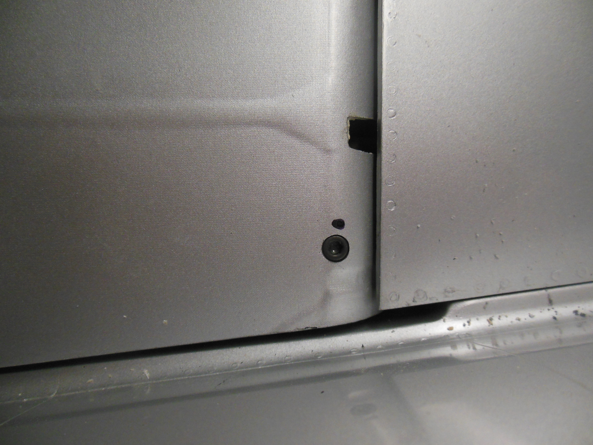
I'm using cardboard tubes as conduit for the wires coming forward from the tail. Servo wires in one tube and the electric tail gear / light wires in the other on opposite sides of the fuselage. Here is a hole I made in the accessory wire tube for the spine mounted nav light midway up the tube.


02-28-2016, 11:19 AM
#3221
Here is the top hatch that I make where the full scale front gas tank cover was. Did it a little different this time. I used an Exacto knife, as I usually do, to cut the areas on either side of the carbon fiber reinforced center. Then I tried using a cutting wheel on the inside to cut just through the carbon fiber. Then I was able to finish the cuts with the Exacto knife as before. A little finish cut with my razor saw at the ends of the Dremel cuts. Much better than cutting the whole CF with the saw. Worked great and was very quick.


02-28-2016, 11:26 AM
#3222
These are the cockpit platform mounts. The Corsair did not have a floor in the cockpit. This is why on the early prototypes a clear panel was mounted in the bottom of the cockpit. It was thought that this would help in bomb aiming. It was deleted before production models when it was determined that pilots because disoriented trying to use it.
I leave the floor of the Corsair cockpit as open as possible for this reason. Foot rails were used rather than a floor.
Locating the bottom of the cockpit is the trick. Again, CARF is of no assistance on this.
It looks all cockeyed in the first picture, but this is only an optical effect.


I install a floor under the side consoles, and under the seat frame.
I leave the floor of the Corsair cockpit as open as possible for this reason. Foot rails were used rather than a floor.
Locating the bottom of the cockpit is the trick. Again, CARF is of no assistance on this.
It looks all cockeyed in the first picture, but this is only an optical effect.
I install a floor under the side consoles, and under the seat frame.
Last edited by ram3500-RCU; 02-29-2016 at 03:18 PM.