


Ziroli 1/7 (120") B-25 B scale build
 04-15-2023, 08:45 PM
#151
Senior Member
Thread Starter

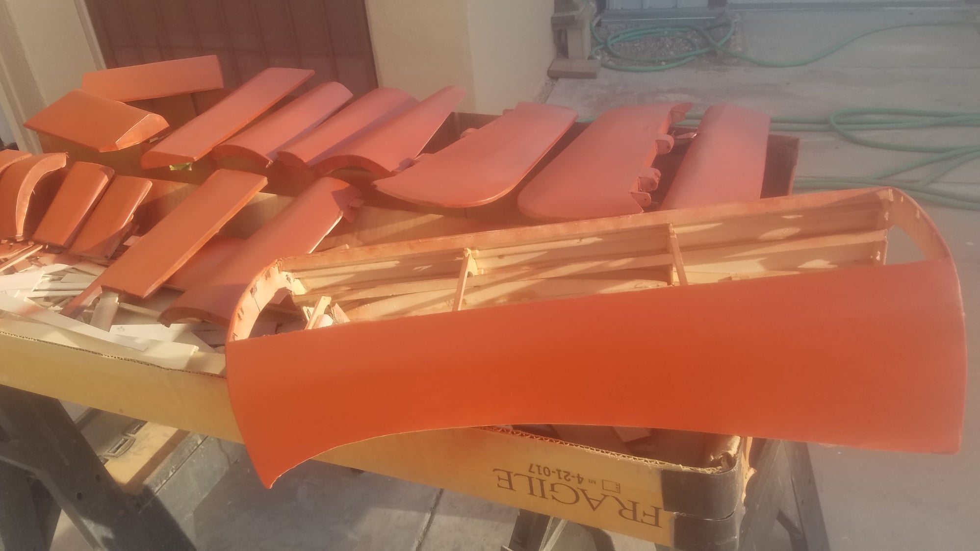
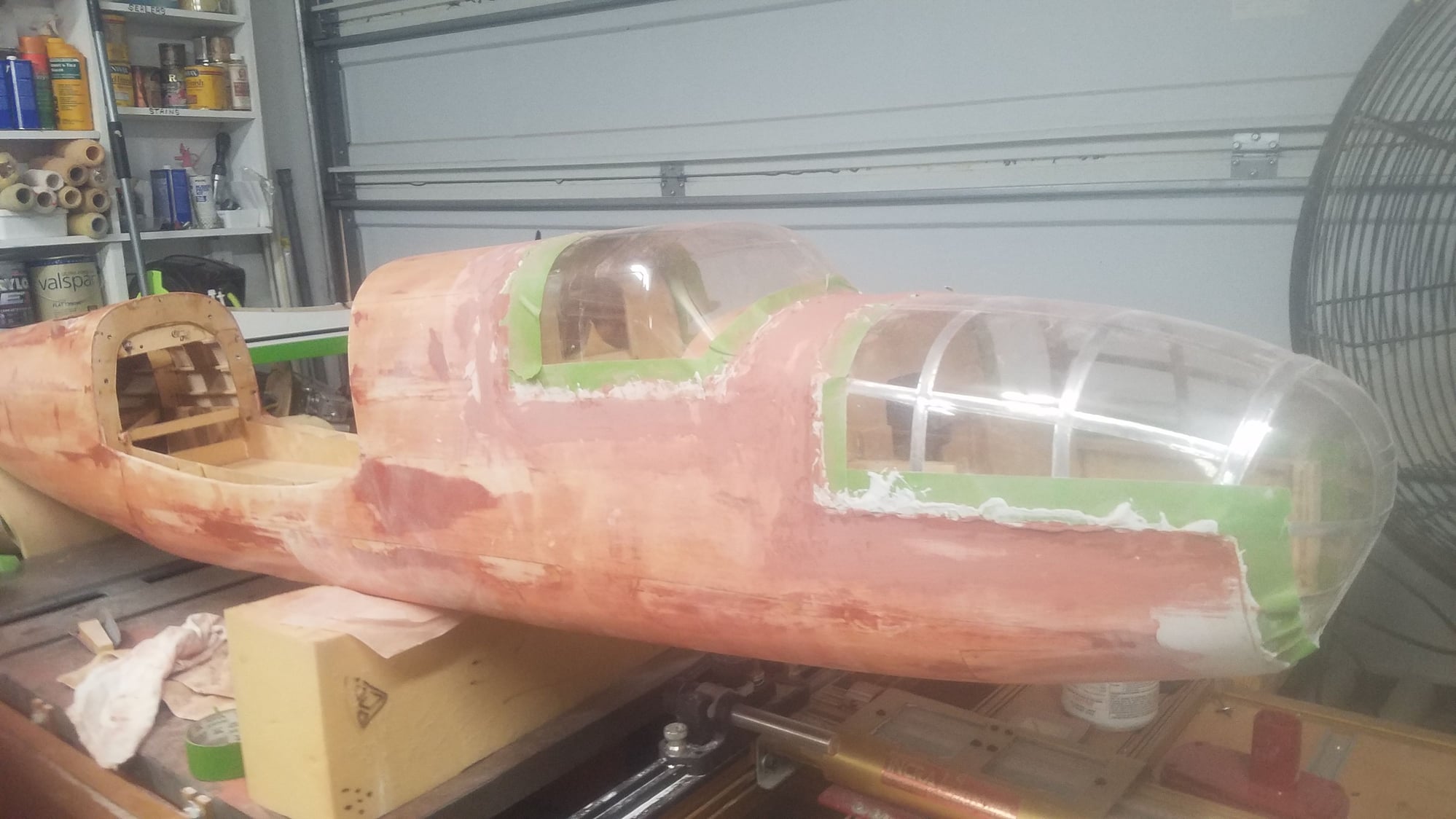
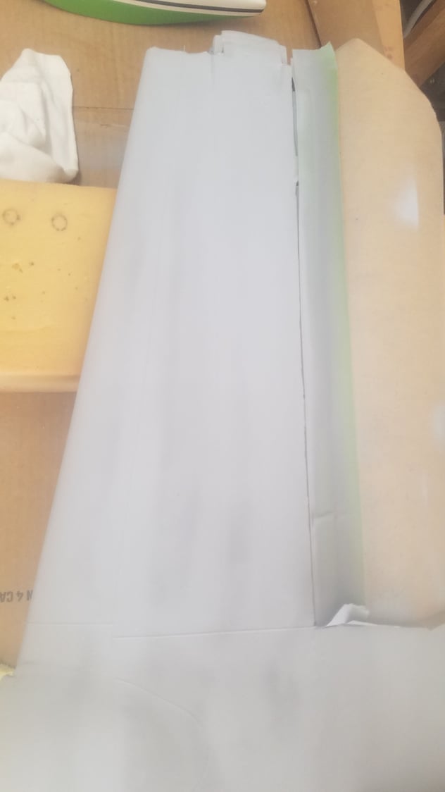
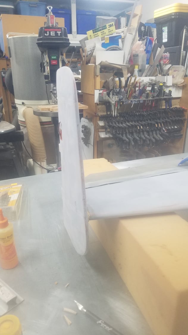
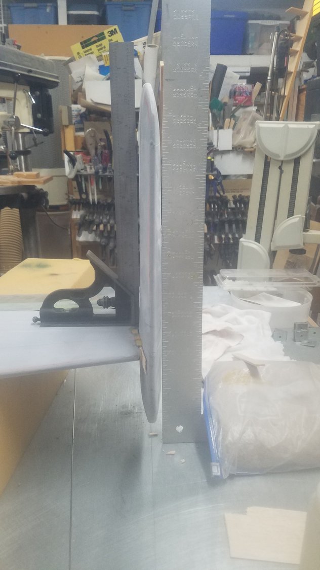
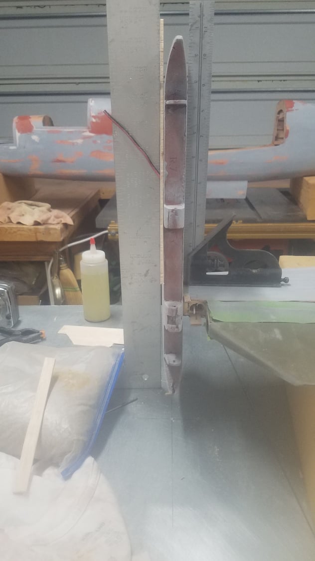
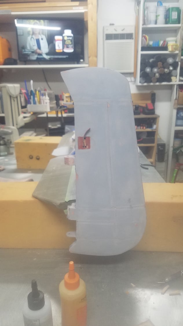
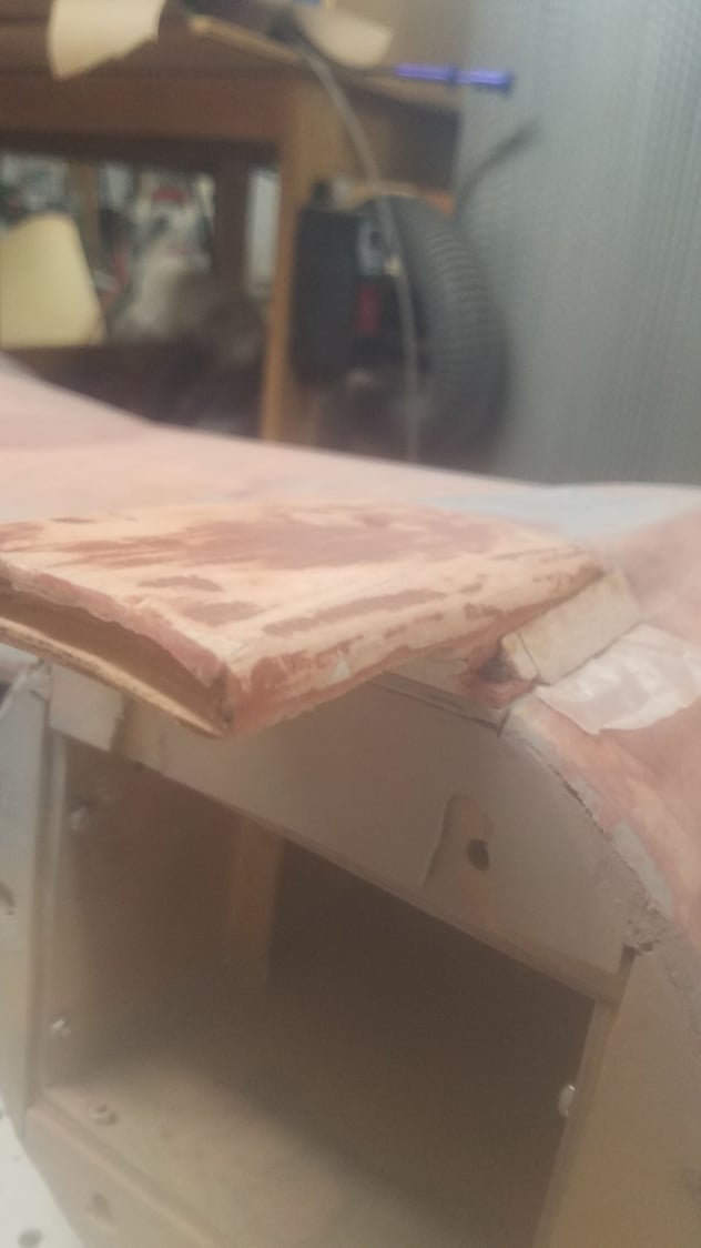
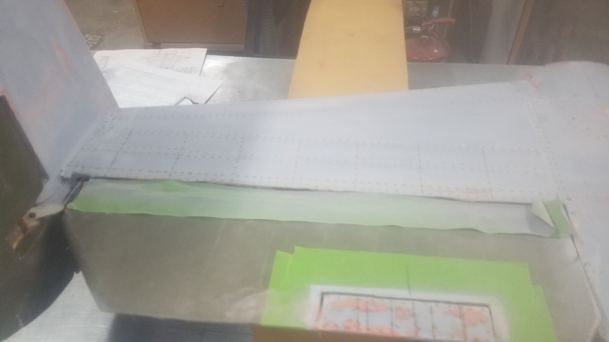
My son and his family have left after spending a great week here at the house. After resting up a few days and getting the house back in order it was time to get back to the B25. Have you even had that feeling that something was wrong for the scale build. What I discovered was that the ailerons on the B25 are fabric covered and not alum skin. So, I had to strip the balsa and fiberglass off the ailerons, rebuild the ribs and set up to be covered in Oratex cloth. Because I used the plywood center section it was somewhat easier to strip out the damaged ribs and replace with new ones which would align with the leading and trailing edges. As I have never used Oratex before this was a learning experience and I found it to be very easy to use. It comes from Germany and is a lighter version of the cloth they use on full size aircraft. Model Oratex also has the glue already on one side like Monocoat that is heat applied. This is real fabric and has a distinctive weave and stretches very well with heat. You first attach the edges with lower heat stretching as you go, then shrink the fabric. Then you go to high heat and repeat the shrinking while making sure you go slow and apply pressure to get the glue to better attach to the balsa. The photos show the ailerons, rudders and elevators covered and they will get painted with the rest of the plane. Covering all the pieces took about 7 hours and I got faster with the more that I covered. This is outstanding material, although it is pretty pricey, and it comes in various colors that are in the cloth and not the glue. Cutting out the trim tabs proved to be the biggest issue as the cloth can shrink away from the edge. This will be corrected in the painting process.
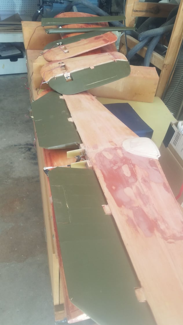
Ailerons, elevators, left and right rudder.
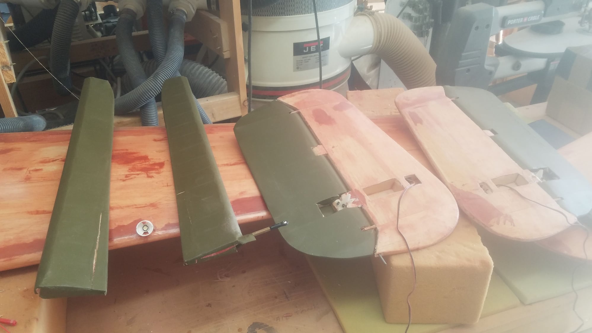
Ailerons and left rudder.
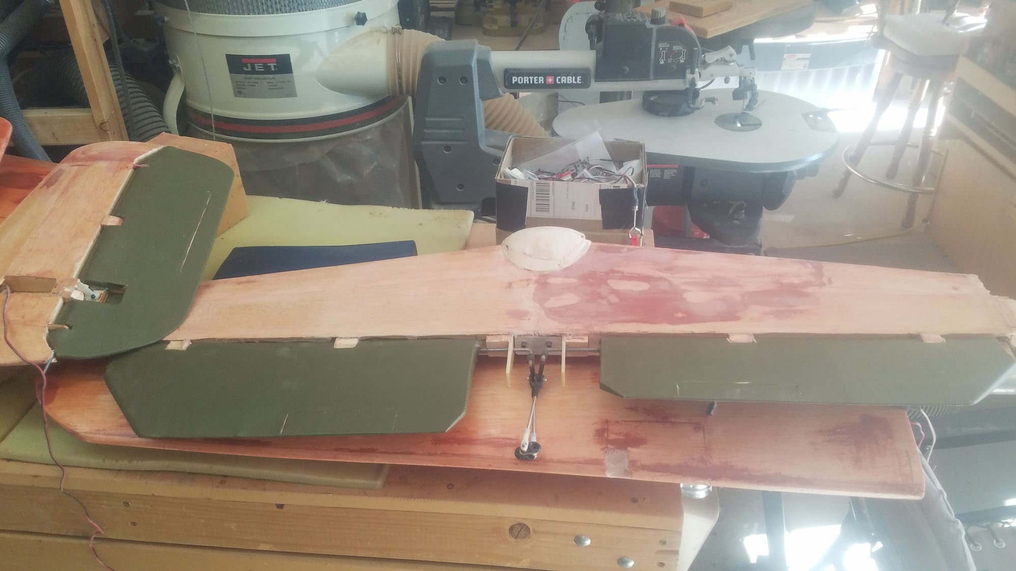
Elevators and right rudder.
Ailerons, elevators, left and right rudder.
Ailerons and left rudder.
Elevators and right rudder.
 05-01-2023, 08:21 PM
#152
Senior Member
Thread Starter
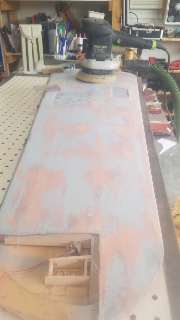
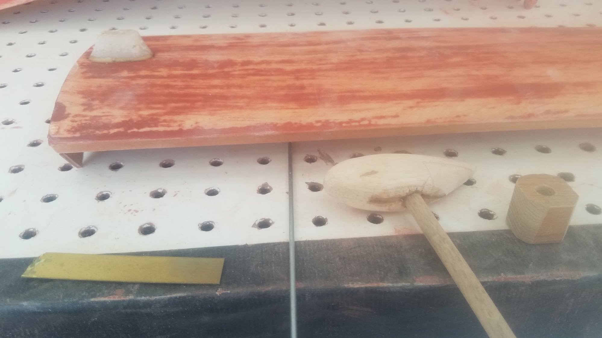
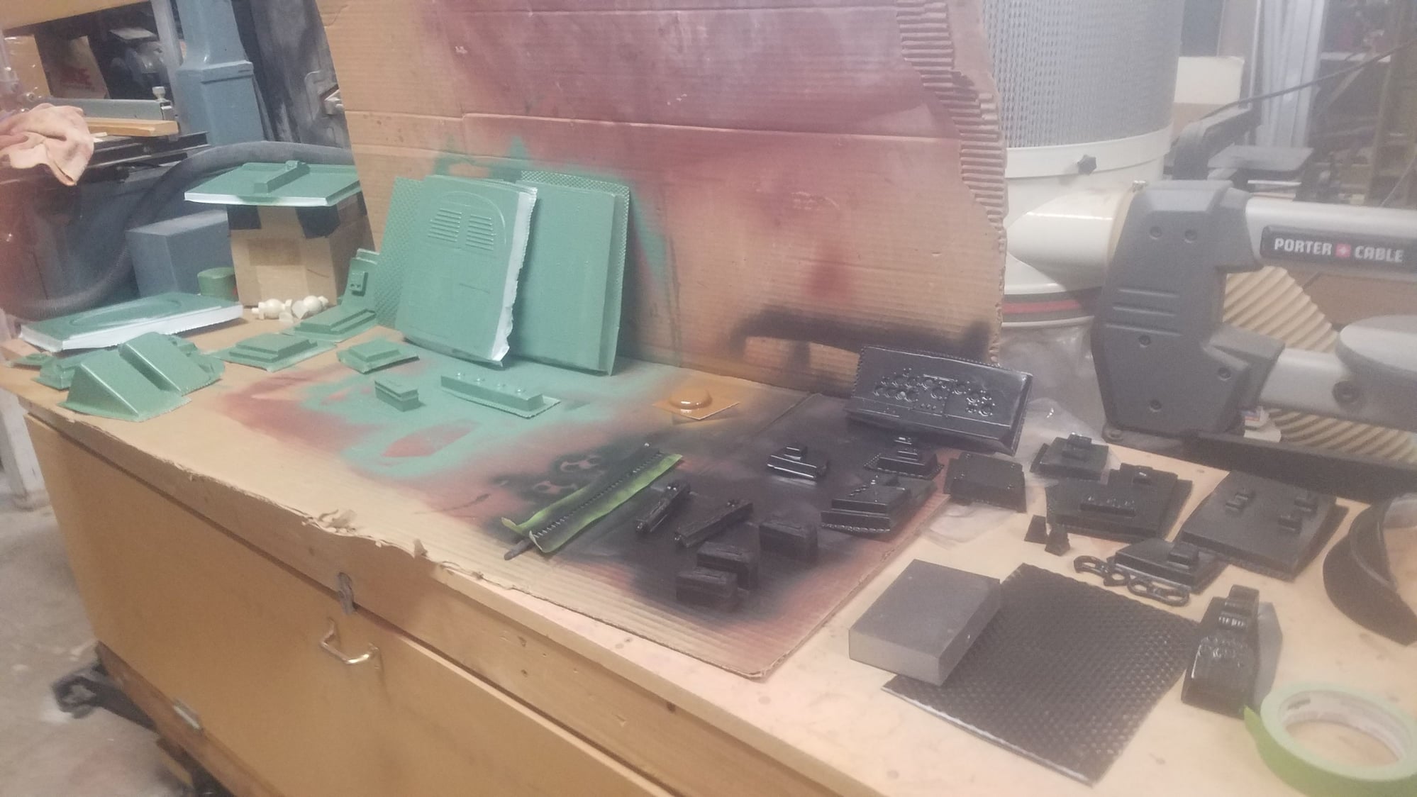
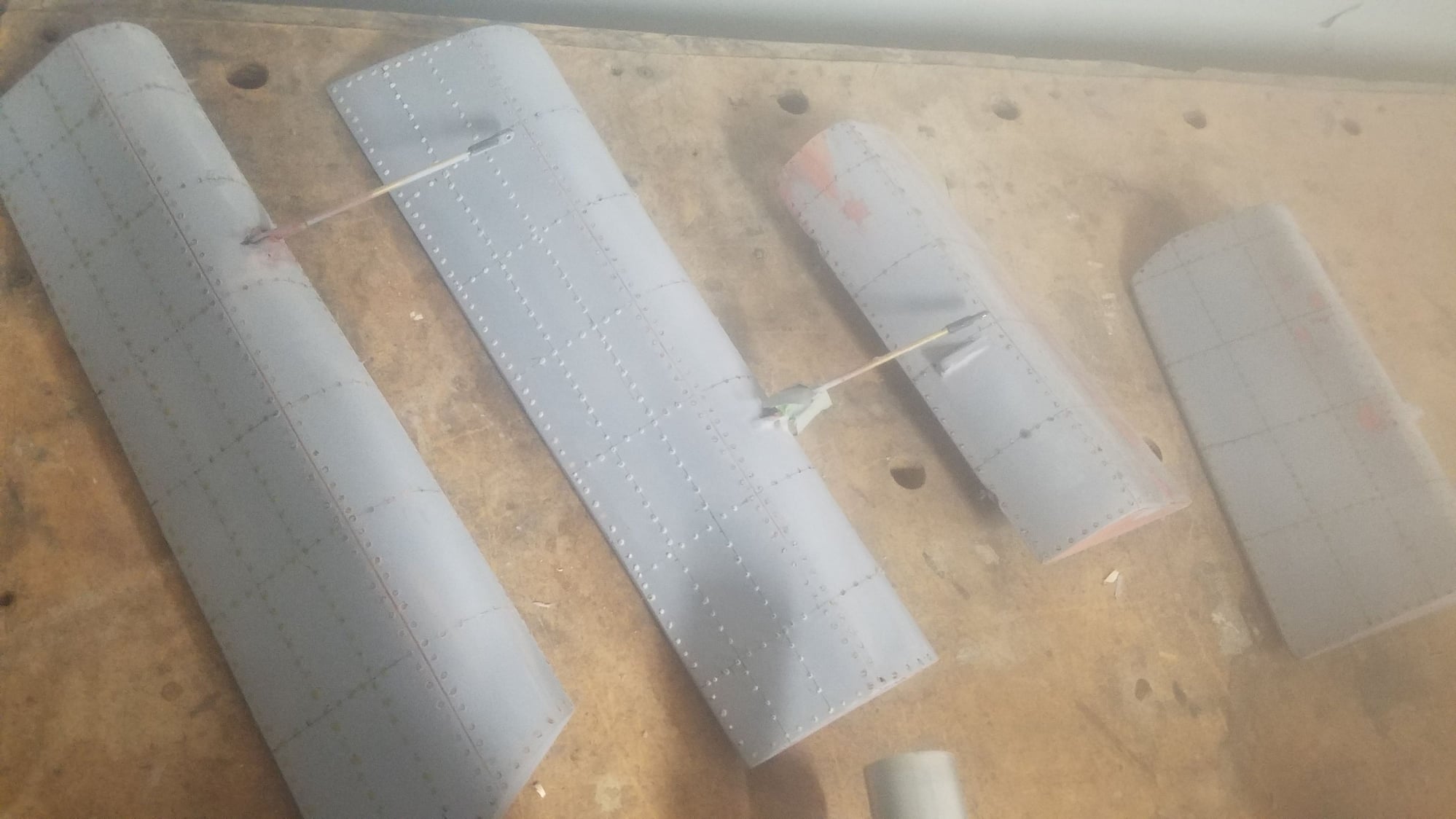
I have been applying multiple coats of polyacrylic and sanding. Now it is time for the primer filler, either red or gray. Tried both; and red sands off easier but make a bigger mess, gray sands harder but works quite well and not so messy. After several hours of hand sanding the filler, I realized this would be a much better job for my Festool sander and vacuum. I also combined it with my sanding table and there was little or no dust flying around the shop that would be coating everything in sight. Used 180 grit to knock off the primer and then used 220 grit to finish the surface. The result was really outstanding and extra low areas show up rather easily so you can use the puddy filer to bring it on up and sand it out. Even using the sander is still takes many hours to just get these items accomplished.
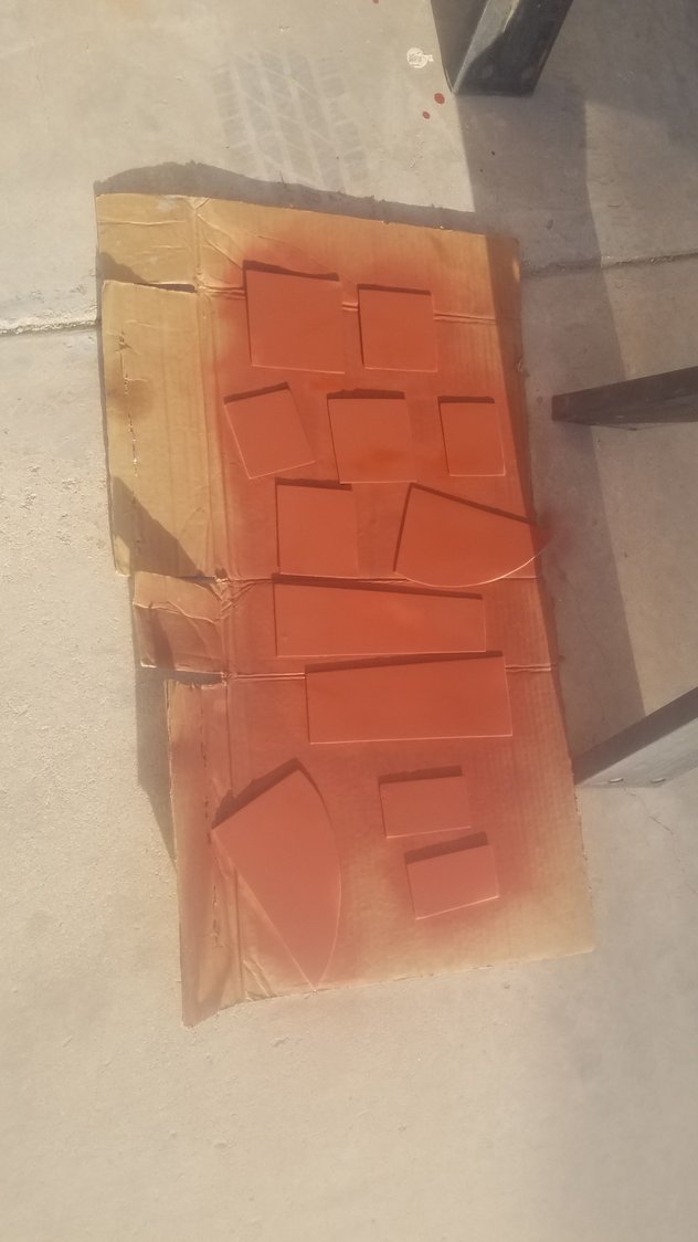
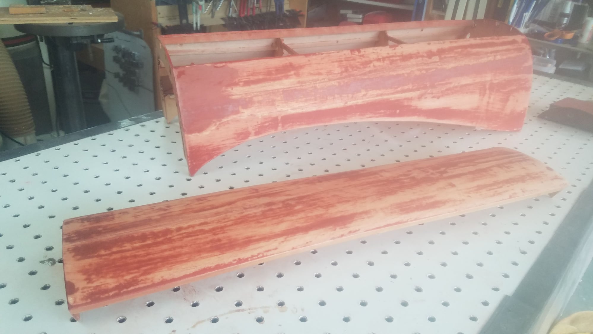
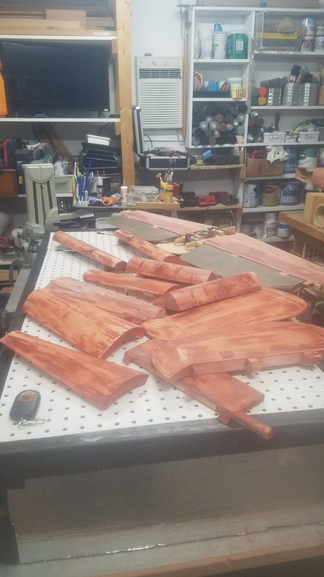
Flat panels are coated.
Center section, hatch, flaps, gear doors, cowl hatches, and vertical fins are sprayed.
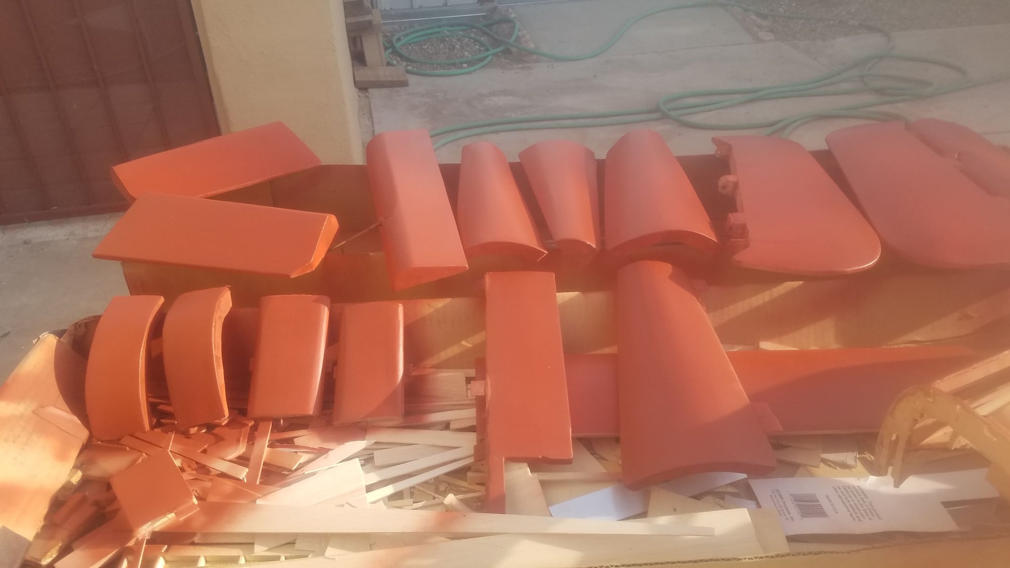
outboard wings are sprayed red on top and gray on the bottom as a test.
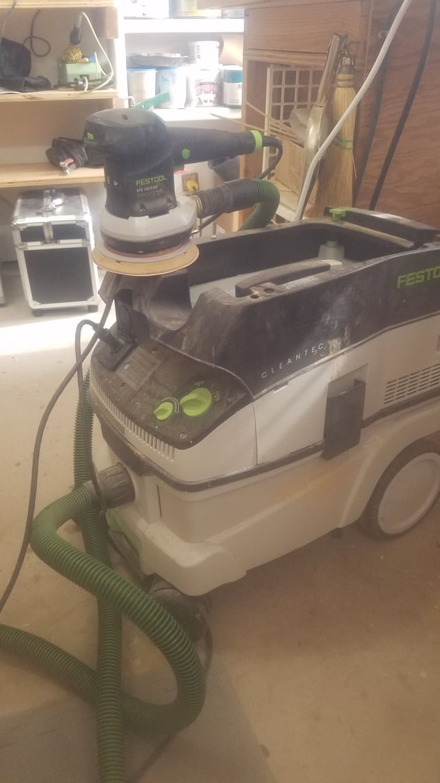
This is my Festool sander and vacuum system; it was a little pricey but works better than anything I have ever used. It was originally purchased for making furniture but works really well for these large pieces. The vacuum is so good that there is little or no dust when sanding and vacuum is turned on when you pull the trigger on the sander.
Gray filler side is sanded.
Center section and hatch sanded out. Amazing how many low areas are exposed.
The whole batch sanded and puddy filled waiting a final 180 grit sand and then finish sand with 220 grit.
Flat panels are coated.
Center section, hatch, flaps, gear doors, cowl hatches, and vertical fins are sprayed.
outboard wings are sprayed red on top and gray on the bottom as a test.
This is my Festool sander and vacuum system; it was a little pricey but works better than anything I have ever used. It was originally purchased for making furniture but works really well for these large pieces. The vacuum is so good that there is little or no dust when sanding and vacuum is turned on when you pull the trigger on the sander.
Gray filler side is sanded.
Center section and hatch sanded out. Amazing how many low areas are exposed.
The whole batch sanded and puddy filled waiting a final 180 grit sand and then finish sand with 220 grit.
05-03-2023, 06:35 PM
#153
Senior Member
Thread Starter
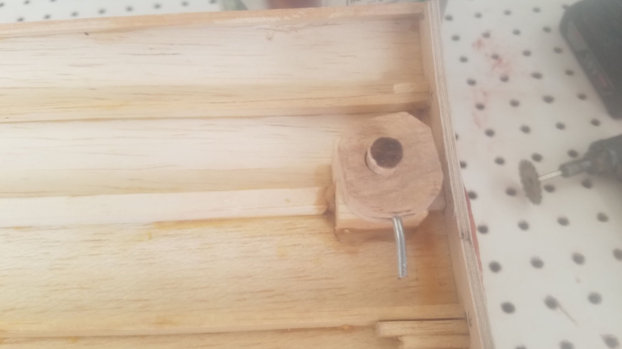
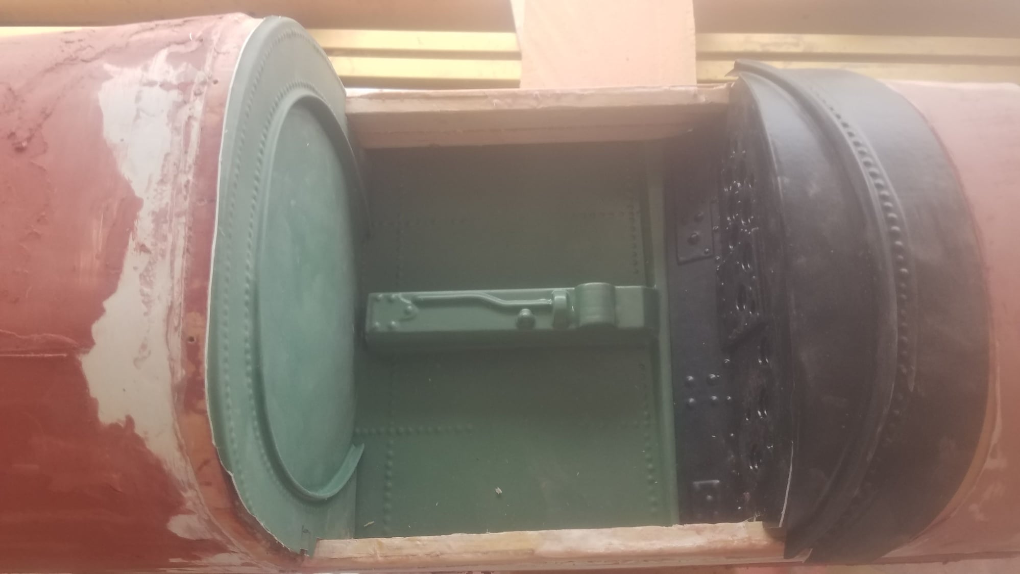
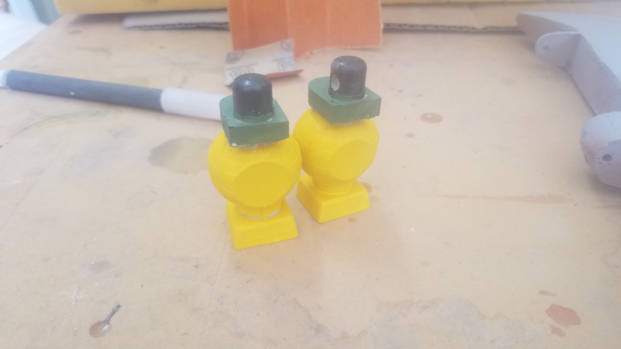
This is my top hatch tie down design. The top hatch which will hold all the internal electronics and pneumatics is now opened by rotating the football antenna 90 degrees. Need to glass the antenna and finish off - works great.
Parts to make up top hatch front hold down. Antenna has brass plate inserted in slot in antenna and dowel, this allows twisting motion to be applied to the dowel. The antenna is then inserted into the nylon spacer which is glued to the hatch.
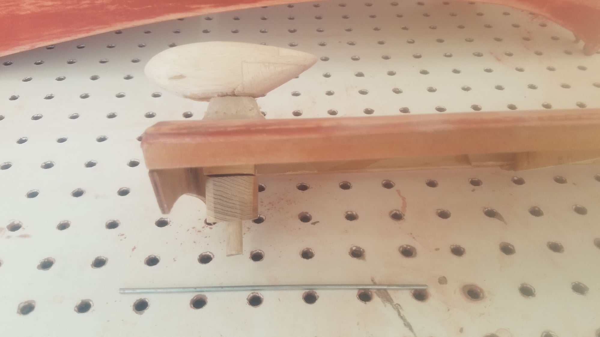
Assembled antenna without metal hold down rod and collar included.
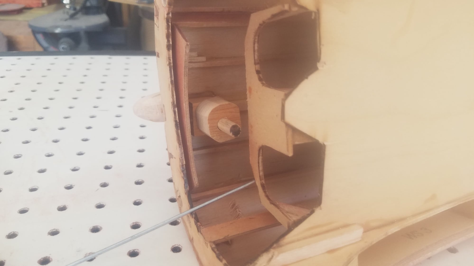
Dowel in lower bearing from antenna to the collar and pin yet to be installed.
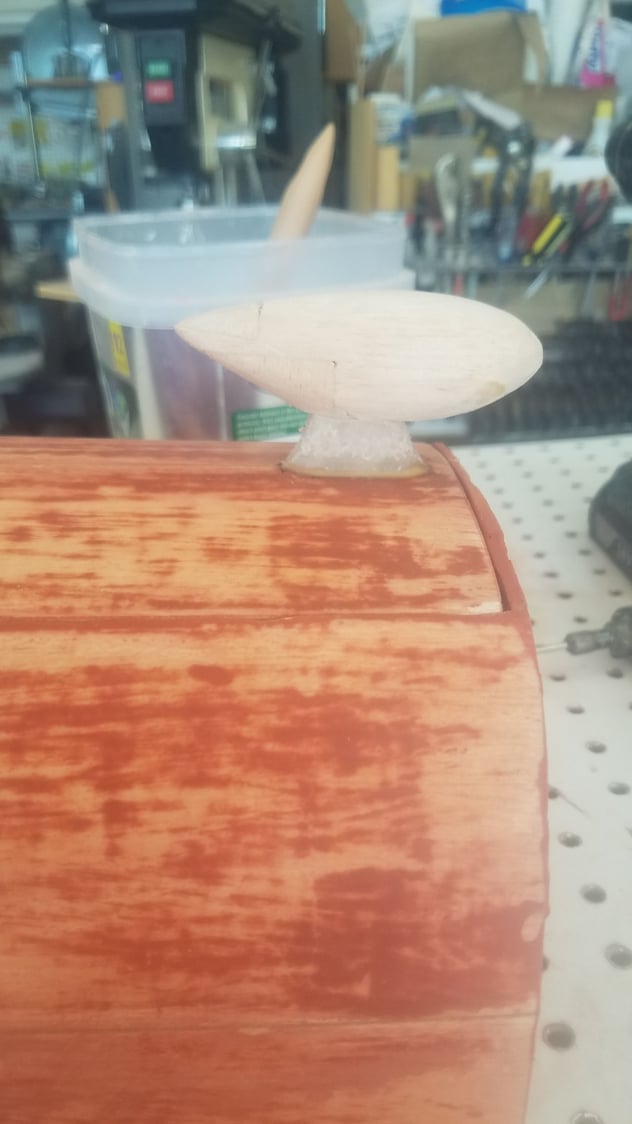
Top hatch held down at the rear with two pins. Front of hatch held down with antenna facing forward. To release hatch, rotate antenna 90 degrees.
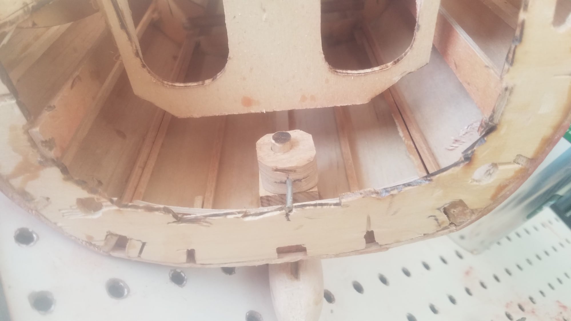
Antenna in locked position. See small notch in the locked location.
Antenna in unlocked location.
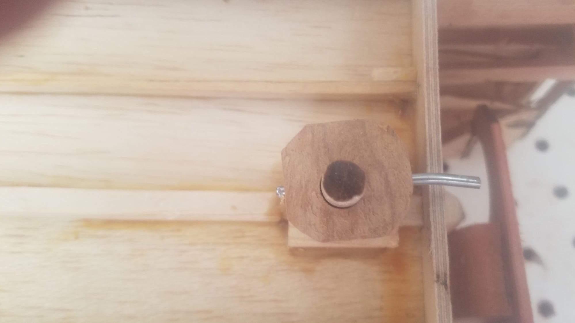
Closeup of locked location and assembly. Pin goes through collar and dowel. To remove the assembly just pull the pin out.
Top hatch held down at the rear with two pins. Note, rotated antenna at 90-degree location.
Top hatch locked down, front and back.
Parts to make up top hatch front hold down. Antenna has brass plate inserted in slot in antenna and dowel, this allows twisting motion to be applied to the dowel. The antenna is then inserted into the nylon spacer which is glued to the hatch.
Assembled antenna without metal hold down rod and collar included.
Dowel in lower bearing from antenna to the collar and pin yet to be installed.
Top hatch held down at the rear with two pins. Front of hatch held down with antenna facing forward. To release hatch, rotate antenna 90 degrees.
Antenna in locked position. See small notch in the locked location.
Antenna in unlocked location.
Closeup of locked location and assembly. Pin goes through collar and dowel. To remove the assembly just pull the pin out.
Top hatch held down at the rear with two pins. Note, rotated antenna at 90-degree location.
Top hatch locked down, front and back.
 06-30-2023, 11:28 PM
#159
Senior Member
Thread Starter
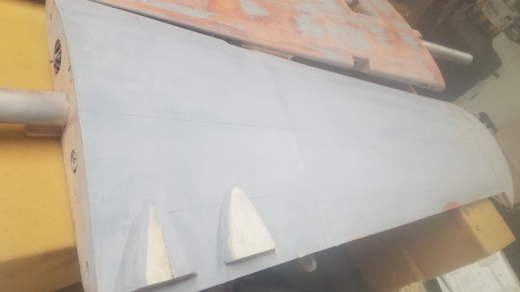
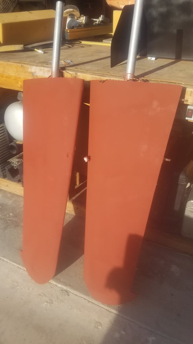
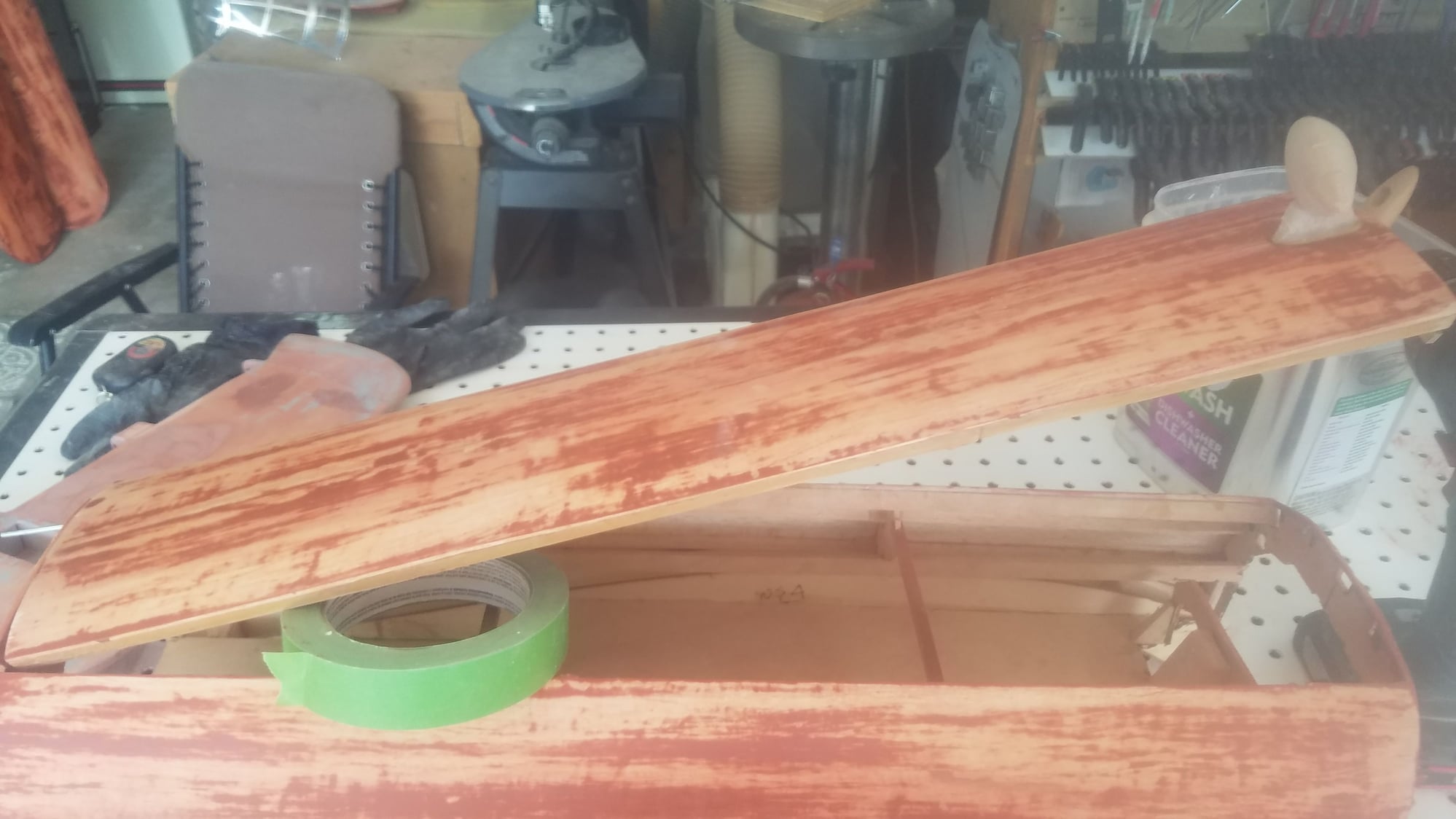
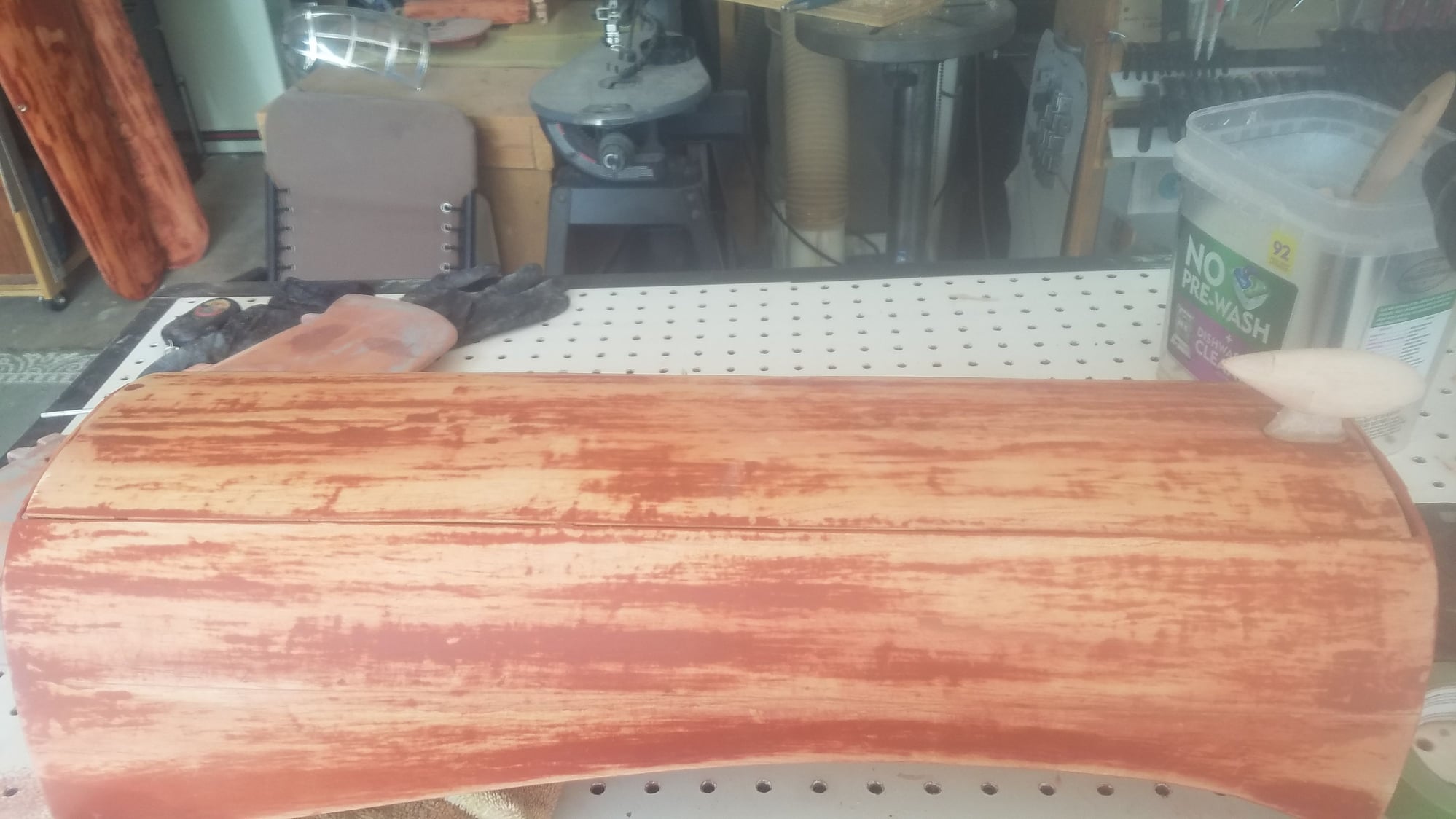
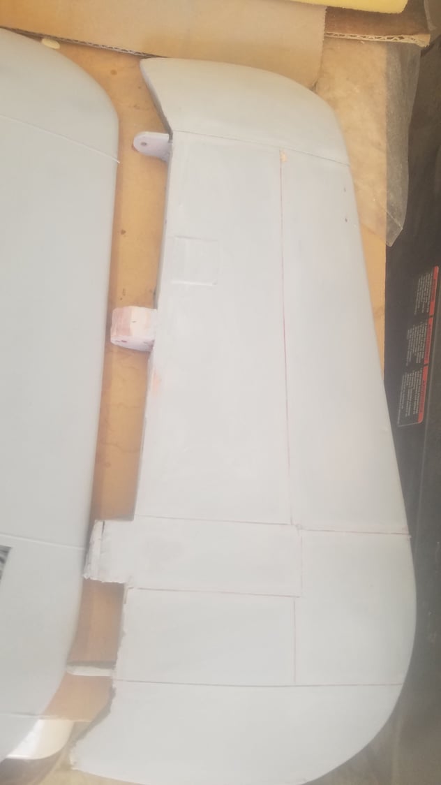
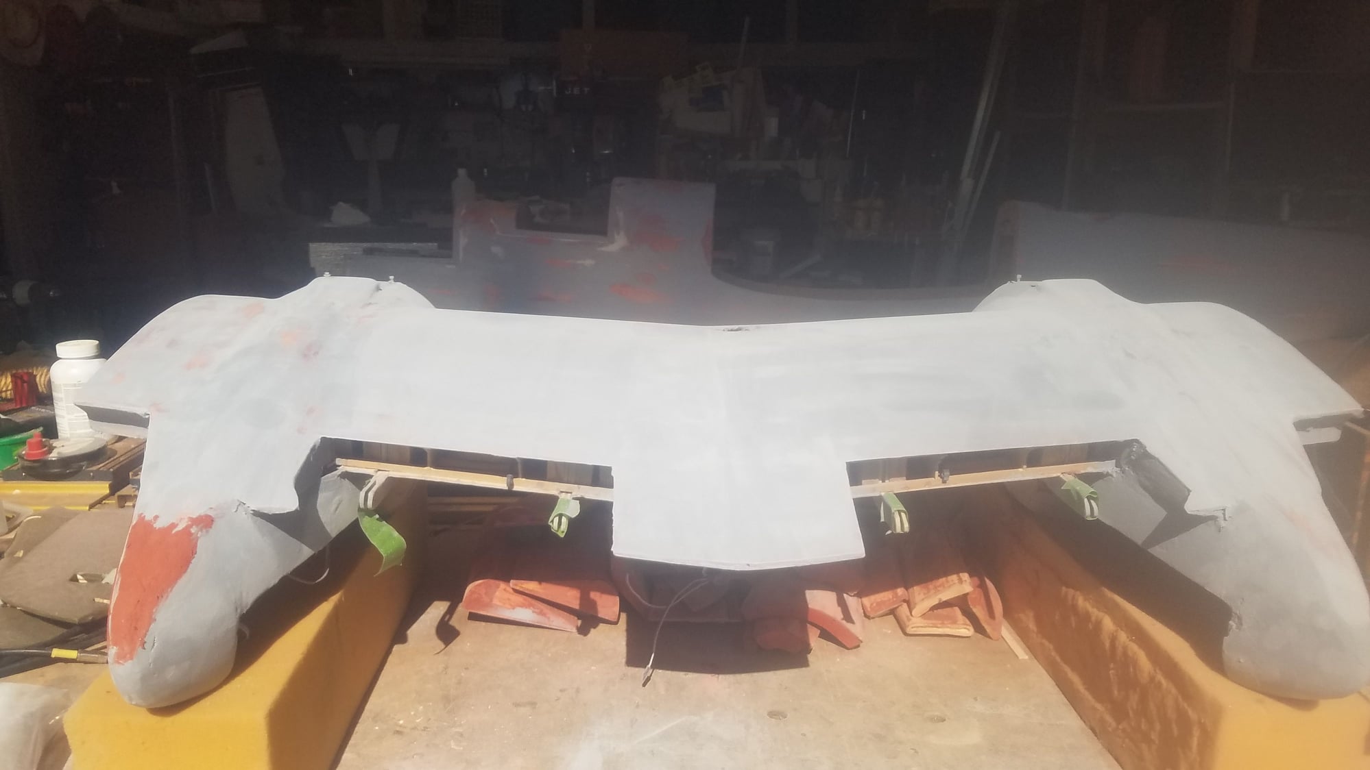
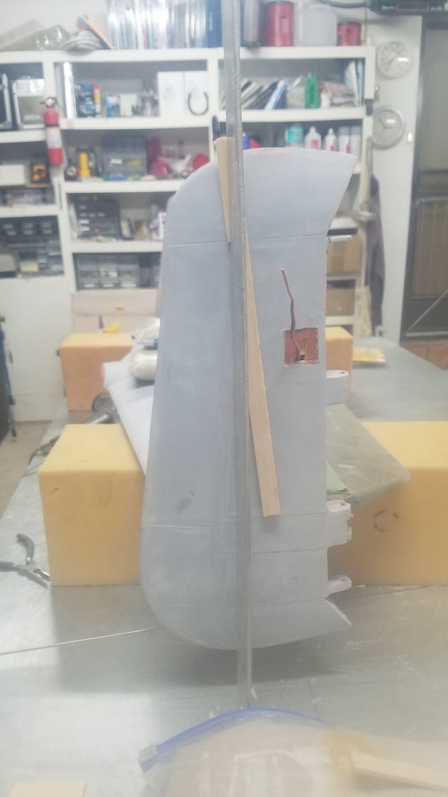
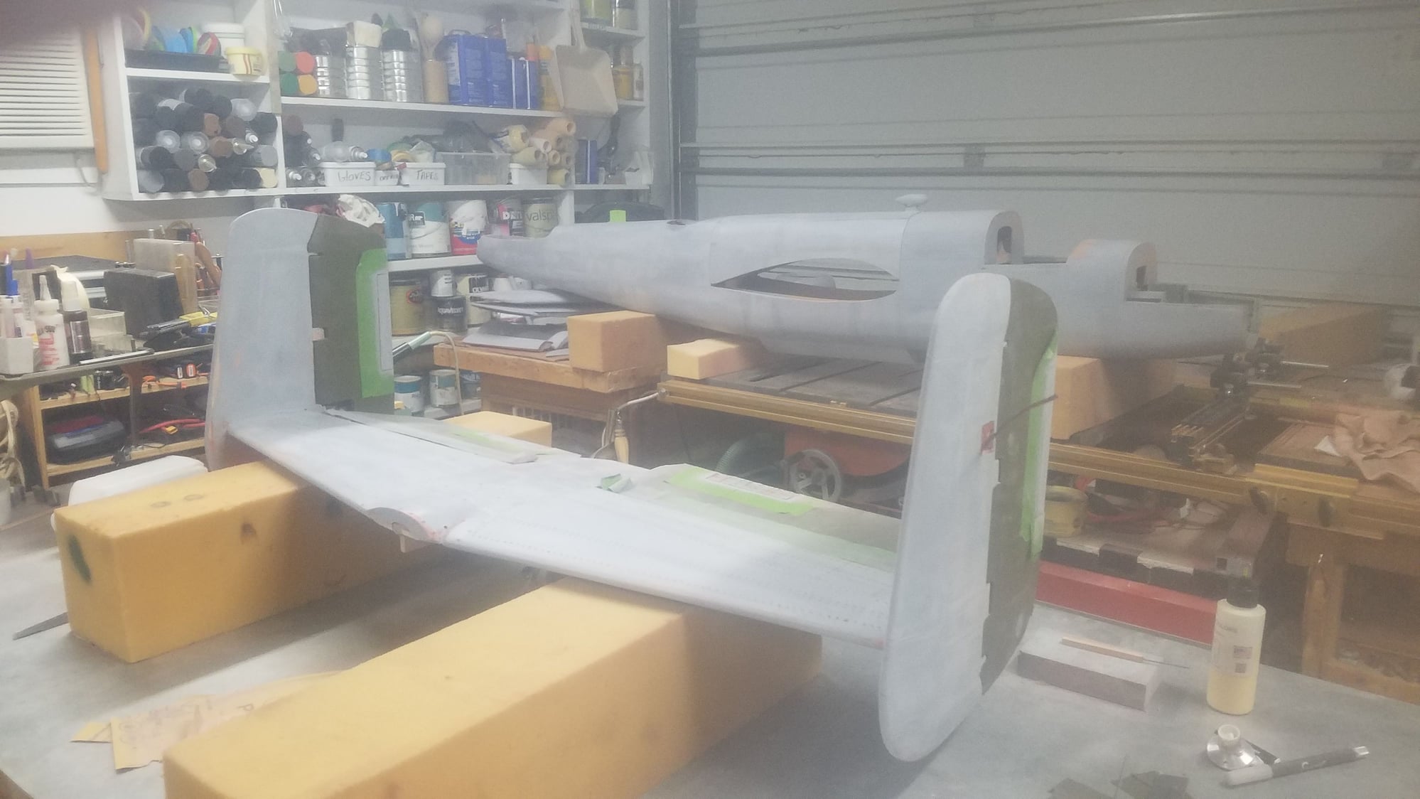
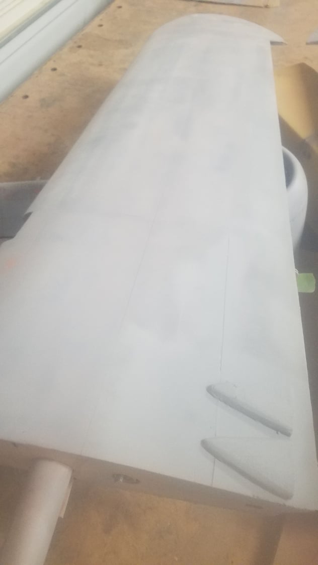
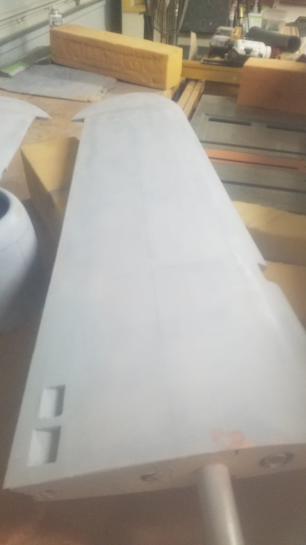
Air vent covers corrected and panel lines installed on top surface of the outer wing.
Panel lines on cowl. Some puddy filler to fill imperfections.
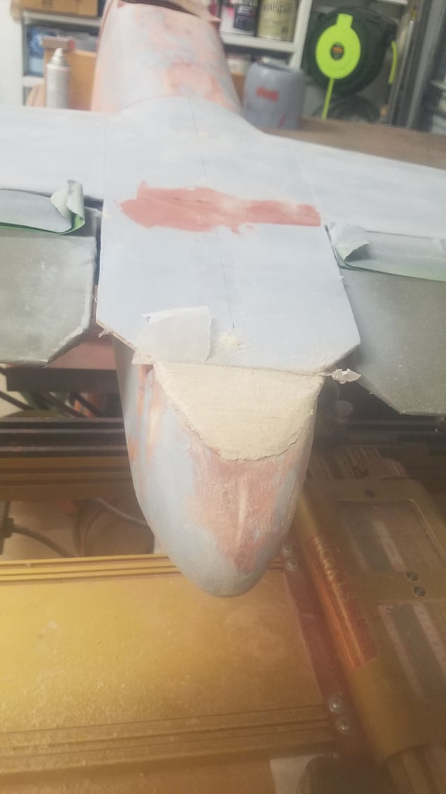
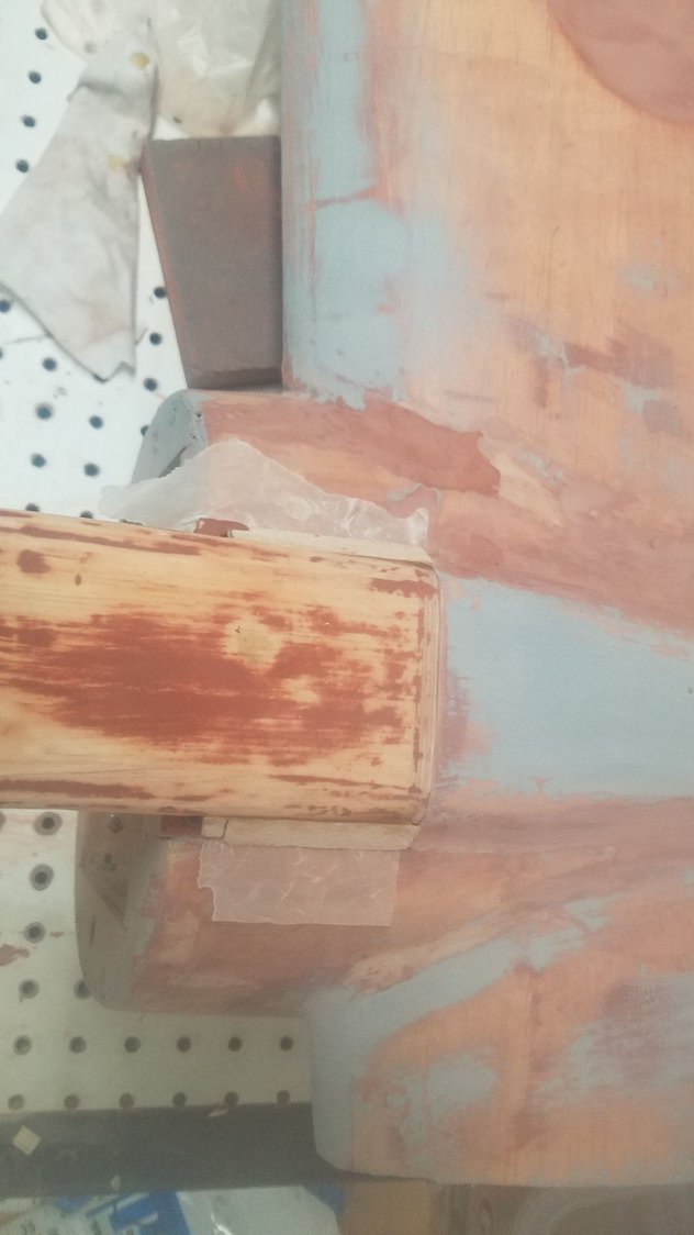
Tail corrected for removable empennage. Will need additional work to cover with fiberglass.
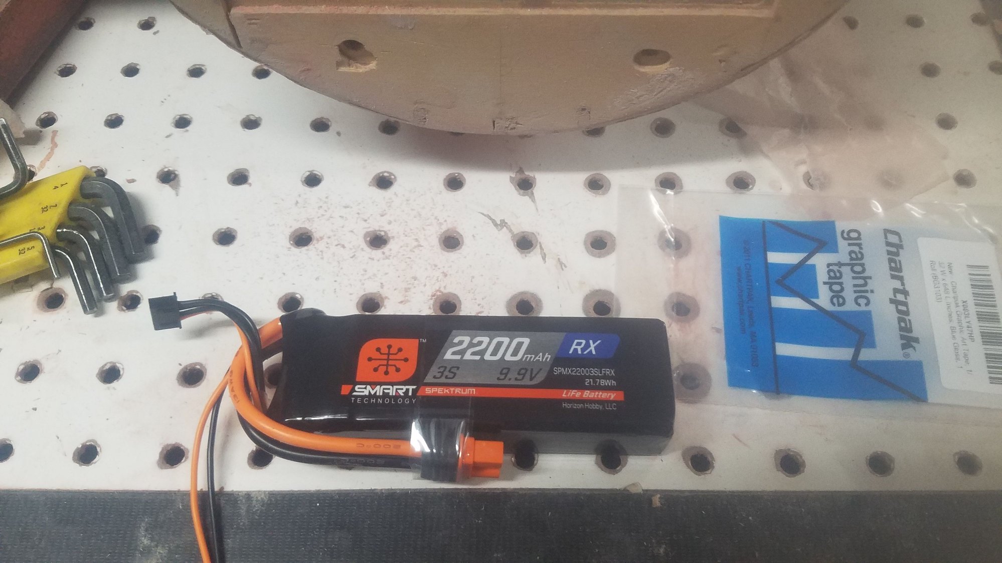
Ignition works better on 9 volts. This is a new 9.9 volt LIFE battery.
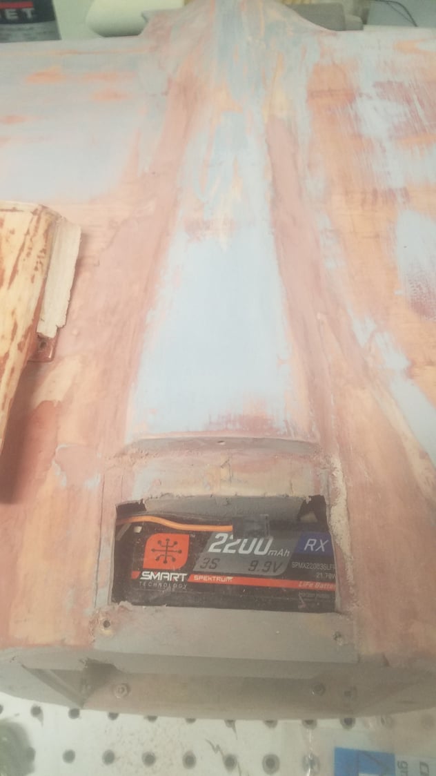
Ignition battery in place. I want as much weight forward as possible.
Engine air intake corrected for new ignition battery installation.
Will need more work with fiberglass to flare in the gussets.
Last edited by rossmick; 06-30-2023 at 11:36 PM. Reason: Corrections
08-04-2023, 04:44 PM
#160
Senior Member
Thread Starter
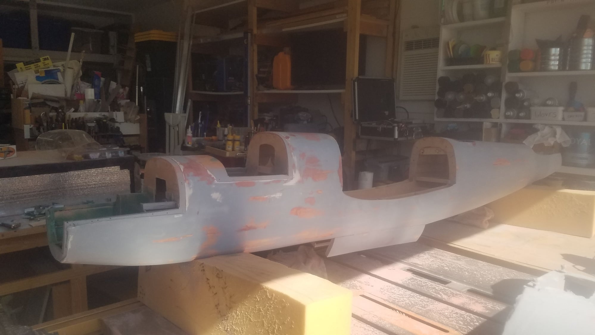
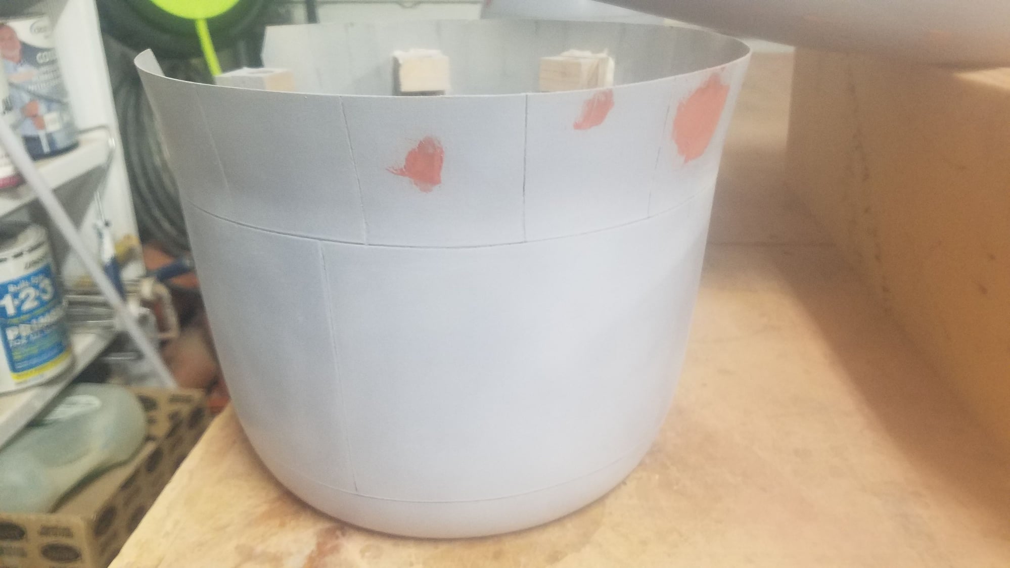
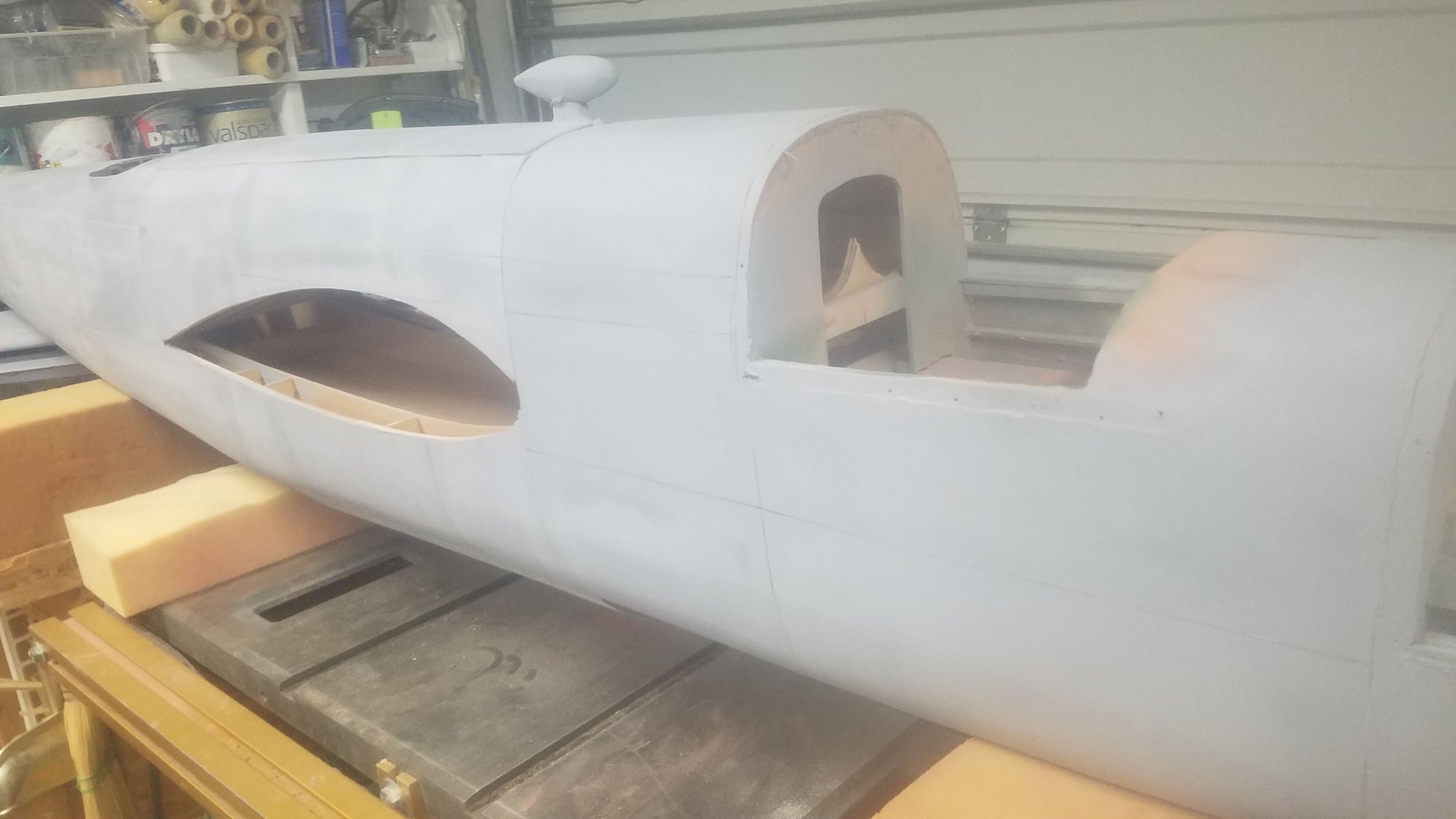
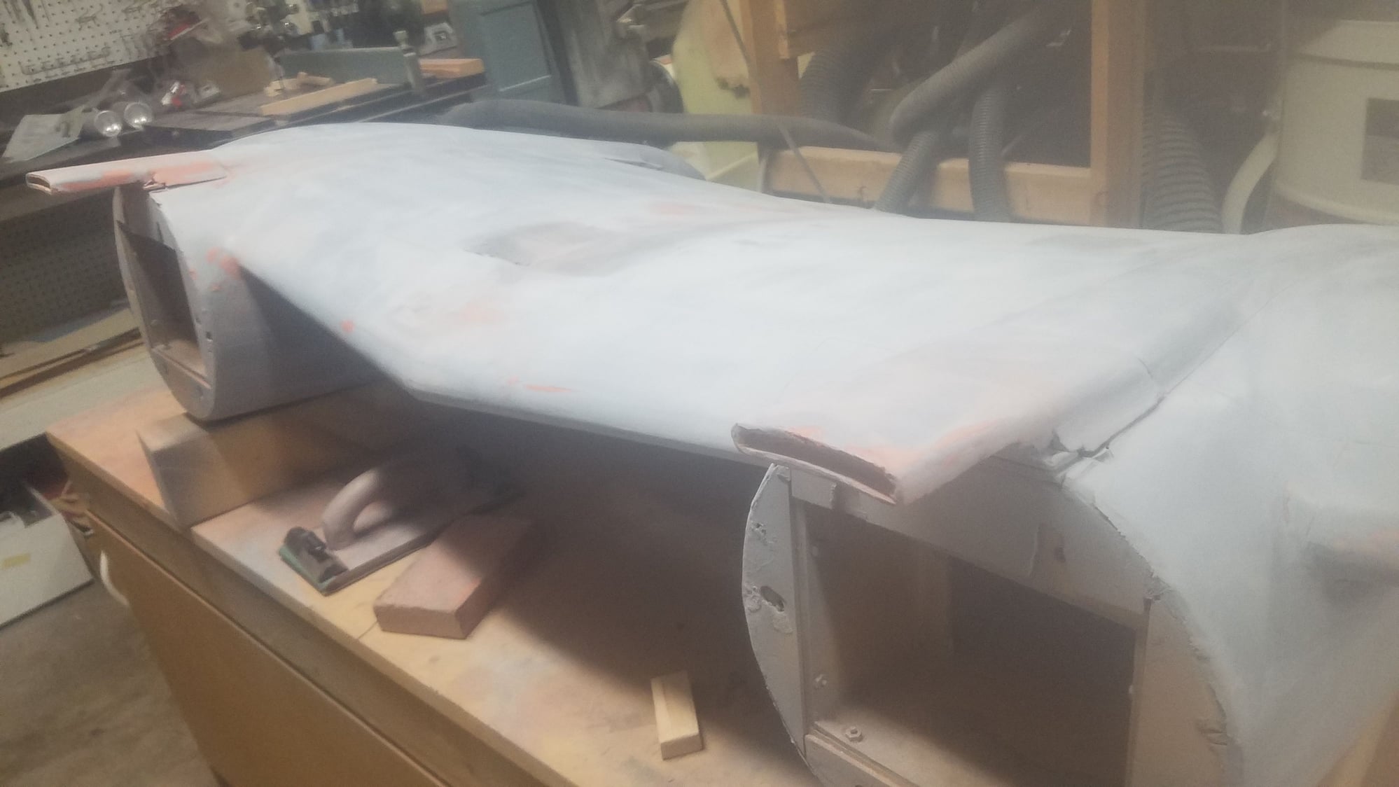
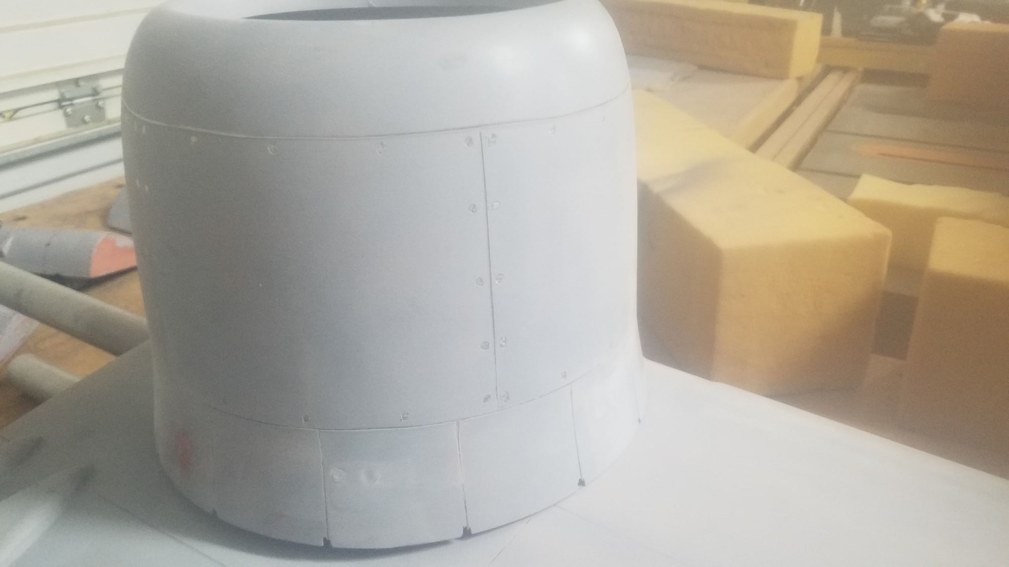
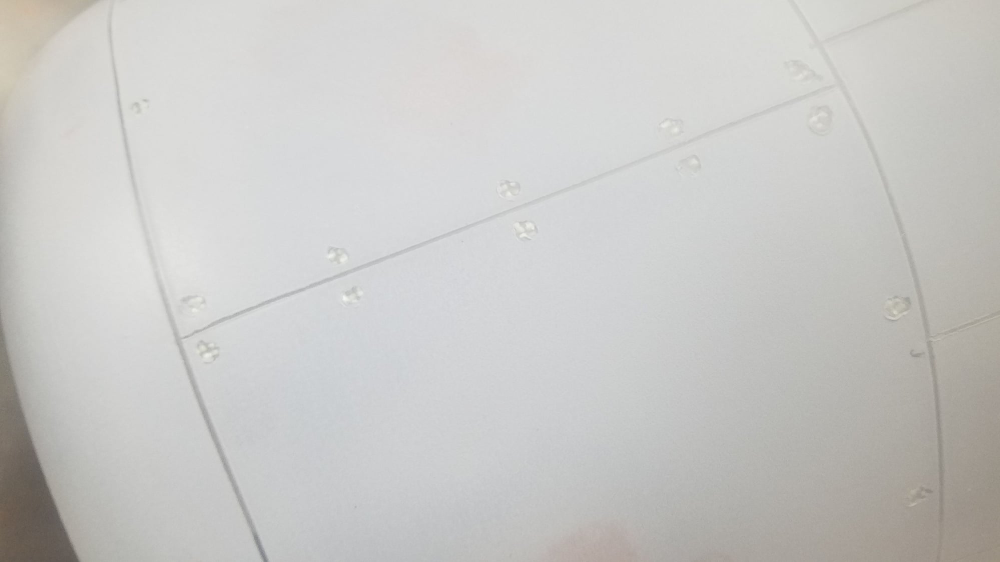
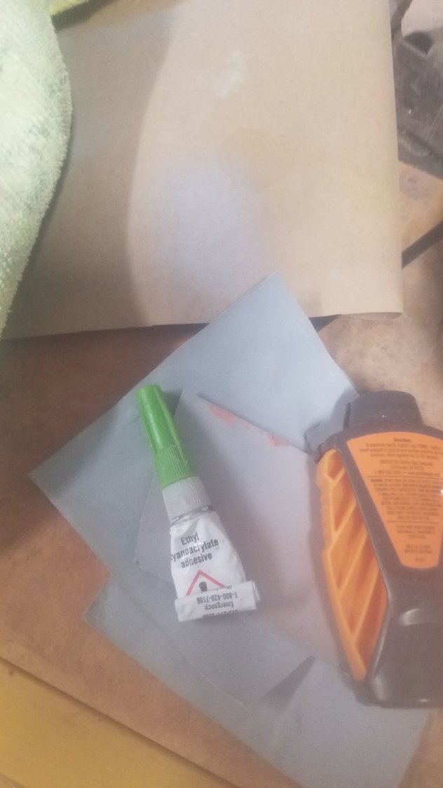
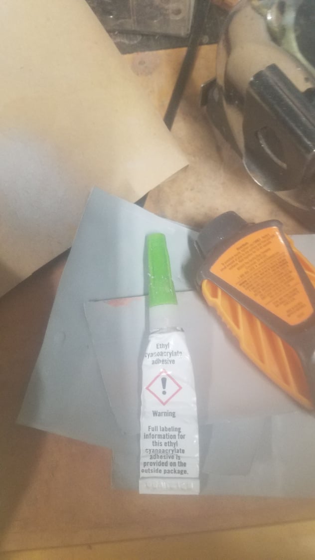
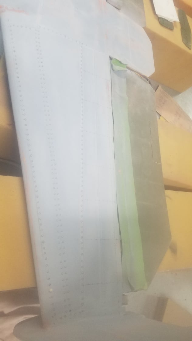
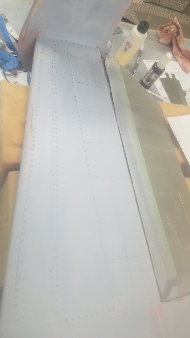
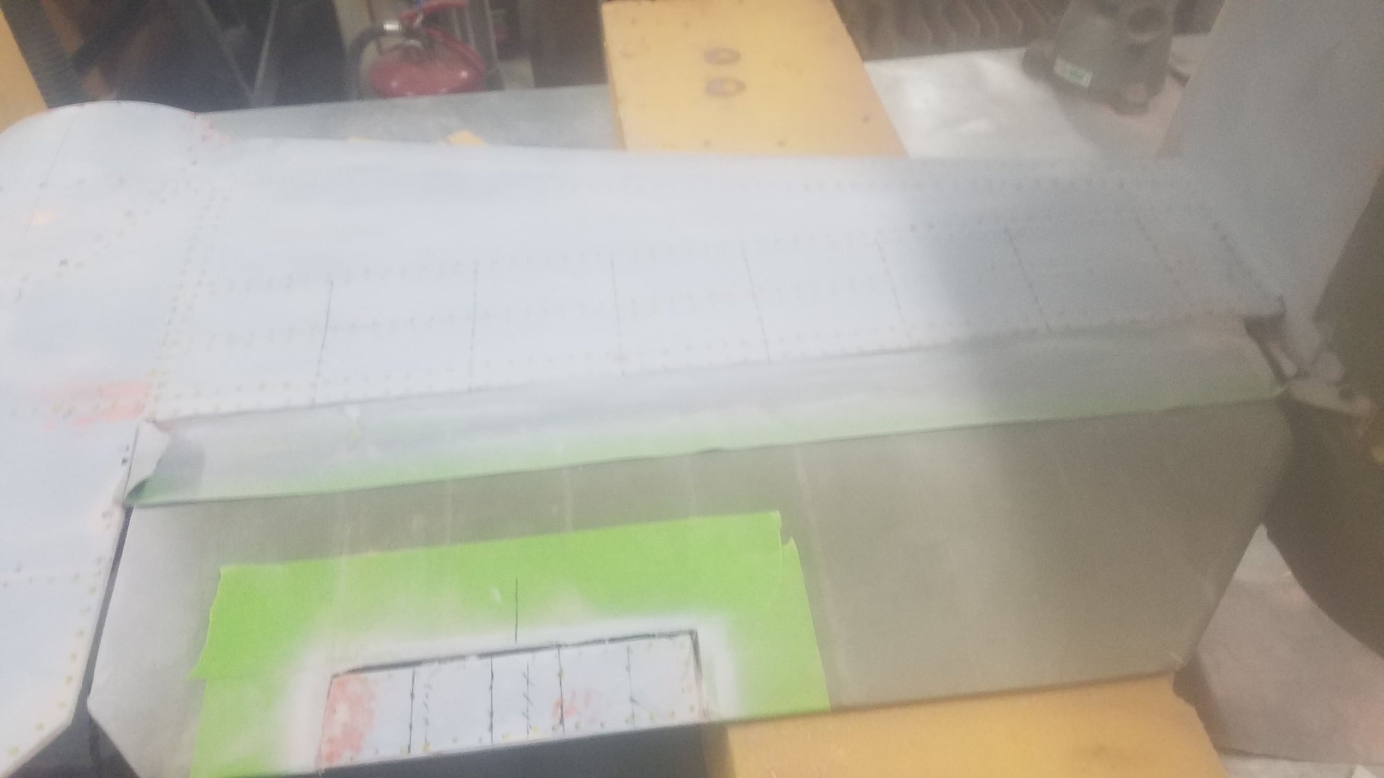
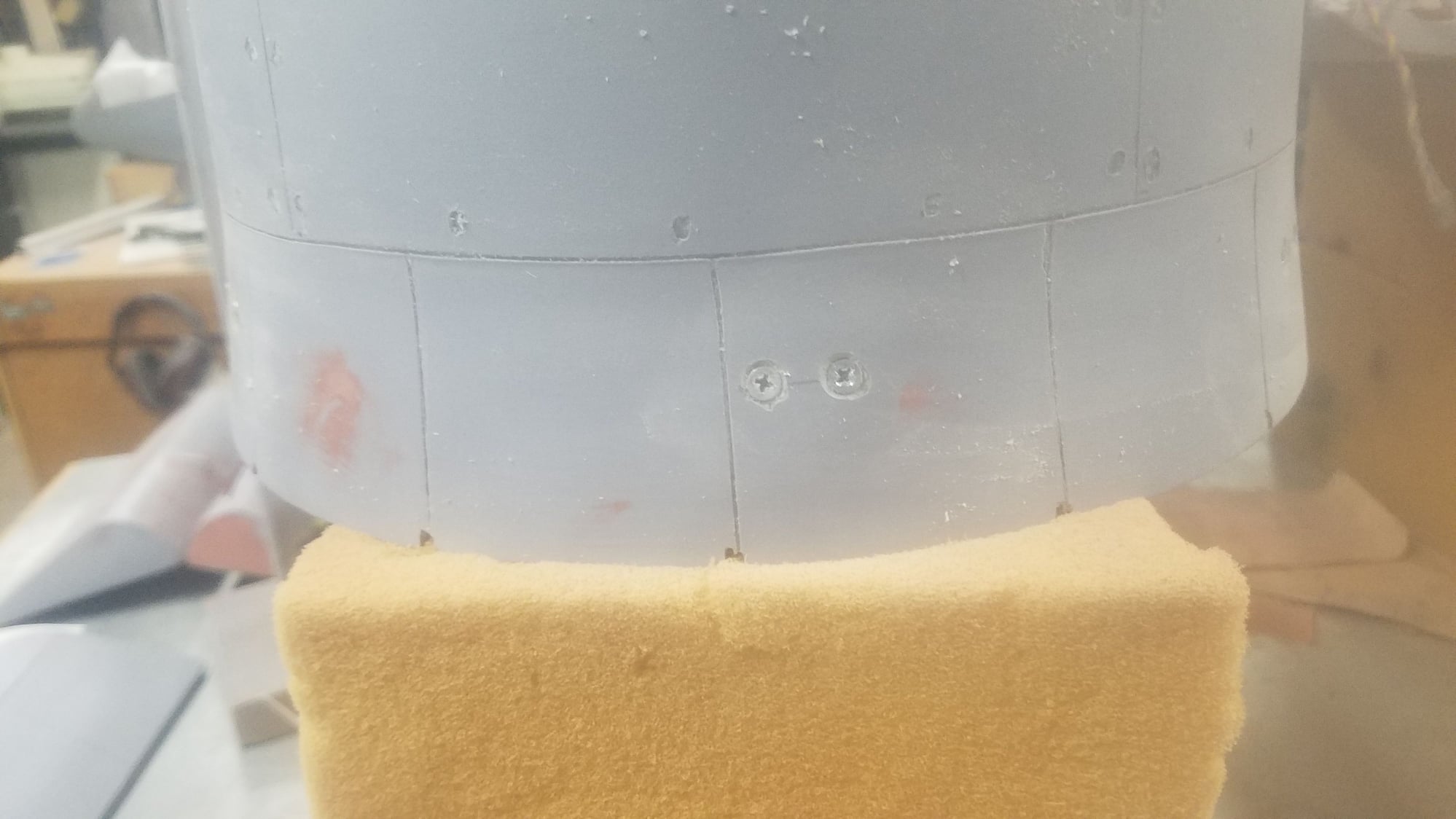
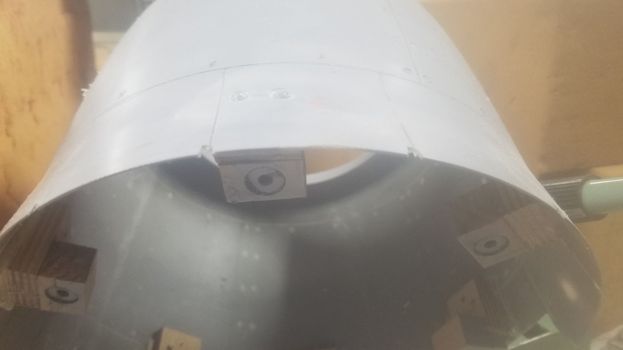
It has been a while since I have last posted due mostly to the effort to produce the panel lines and various rivets on the 25. As this is my first adventure into a higher-grade scale model everything is my first-time attempt. What I am finding out that is that building the plane is the shortest part of the scale build. Laying out the panel lines to scale and then applying the different rivet types is a very long and tedious process. Due to the size of the plane, it has taken many cans of the filler/primer to do the panel lines. I never really counted, but I think I am at least 10 to 12 cans. I followed the process of laying out the scale lines, applying the tape, spraying the tape 4 times and then one more coat to spay overall. Once filler applied and then sanded you can pull the tape to get the panel lines. It is not that it is that hard to do, but it takes a great deal of time. I am more than happy with the results, but it has taken over a month to get the panel lines and to begin applying the rivets. I have been averaging about 3 hours a day and it looks like I may have another month to finish the rivets. Speaking of rivets, there are three types. Two flush types, one for regular rivets and another flush type which I will call a zeus quarter turn fastener which has a flat bladed screw at its center, and the standard raised rivet. The flush type rivets were created using the correct scale size brass tube attached to the soldering iron. The quarter turn type was created by inserting a blade across the tube. The heat is used to melt the filler and fiberglass to make the impression on the skin. This is not a speedy process, trust me, this takes a lot of time and patience. I first laid out and drew the rivet lines and then I marked each rivet location. Double rivets are required around the sprayed in panel lines and single rivets applied over the drawn in lines. I have started on the bottom surfaces as a way to test the various application methods for the raised rivets. I first tried Gorilla glue in a special applanator, I found the rivets produced were too high and had to be sanded back down, they were also too large for a scale look. Be advised that the applicator leaves about a quarter of the glue still in the tube when you can't squeeze out any more glue. I then went back and started using the white Titebond glue. This took several attempts to find the correct size wire to drip the glue in place. I made a small tool to apply the glue. This produced the correct size and height for what I consider the correct rivet size. There are many, many, hours to go to apply the thousands of remaining rivets on this plane. I also discovered that the cowl magnet locations had to be reinforced with screws to keep them from coming loose on the inside of the cowl. Additionally, I found the original wing ducts and vents where not scale and had to be removed and redone, more work needs to be done to get a good finish around the changes.
Panel lines on fuselage. Photos don't do a good job at showing the lines.
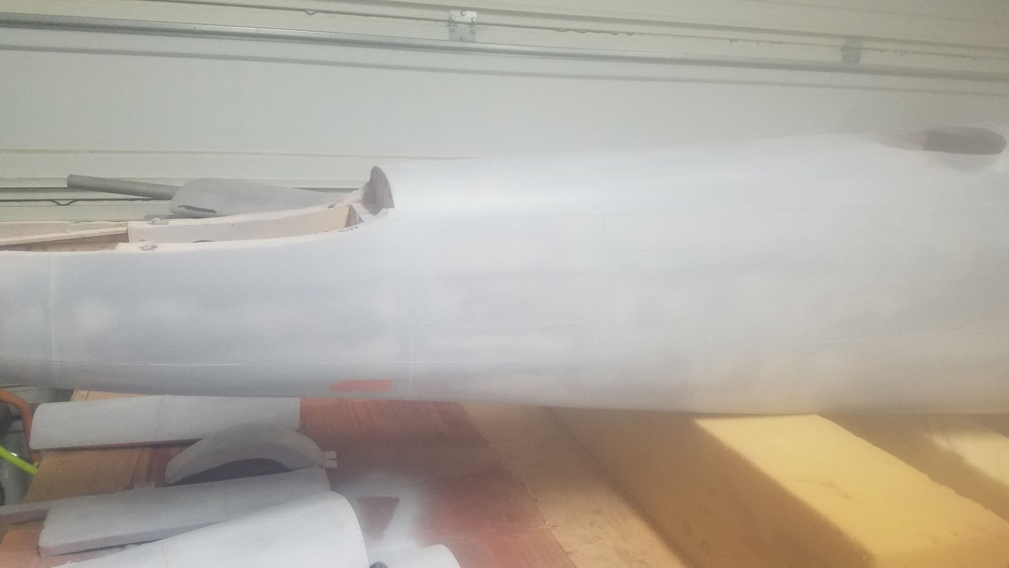
Panel lines on fuselage
Panel lines and air intakes on center section.
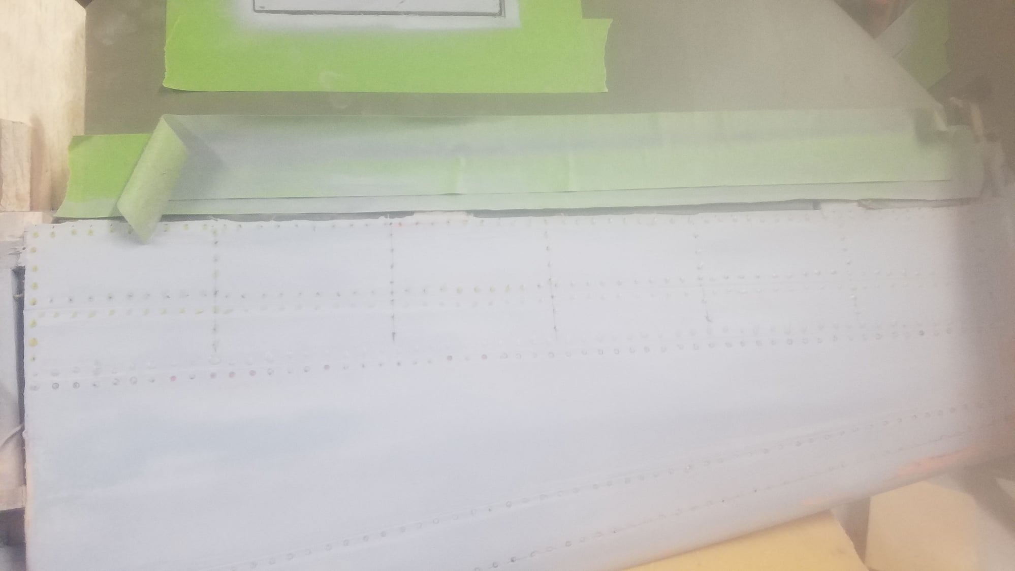
Example of lines drawn on for rivets. The B25 had flush rivets on the first 30 % of the leading edges, then raised rivets for the remainder.
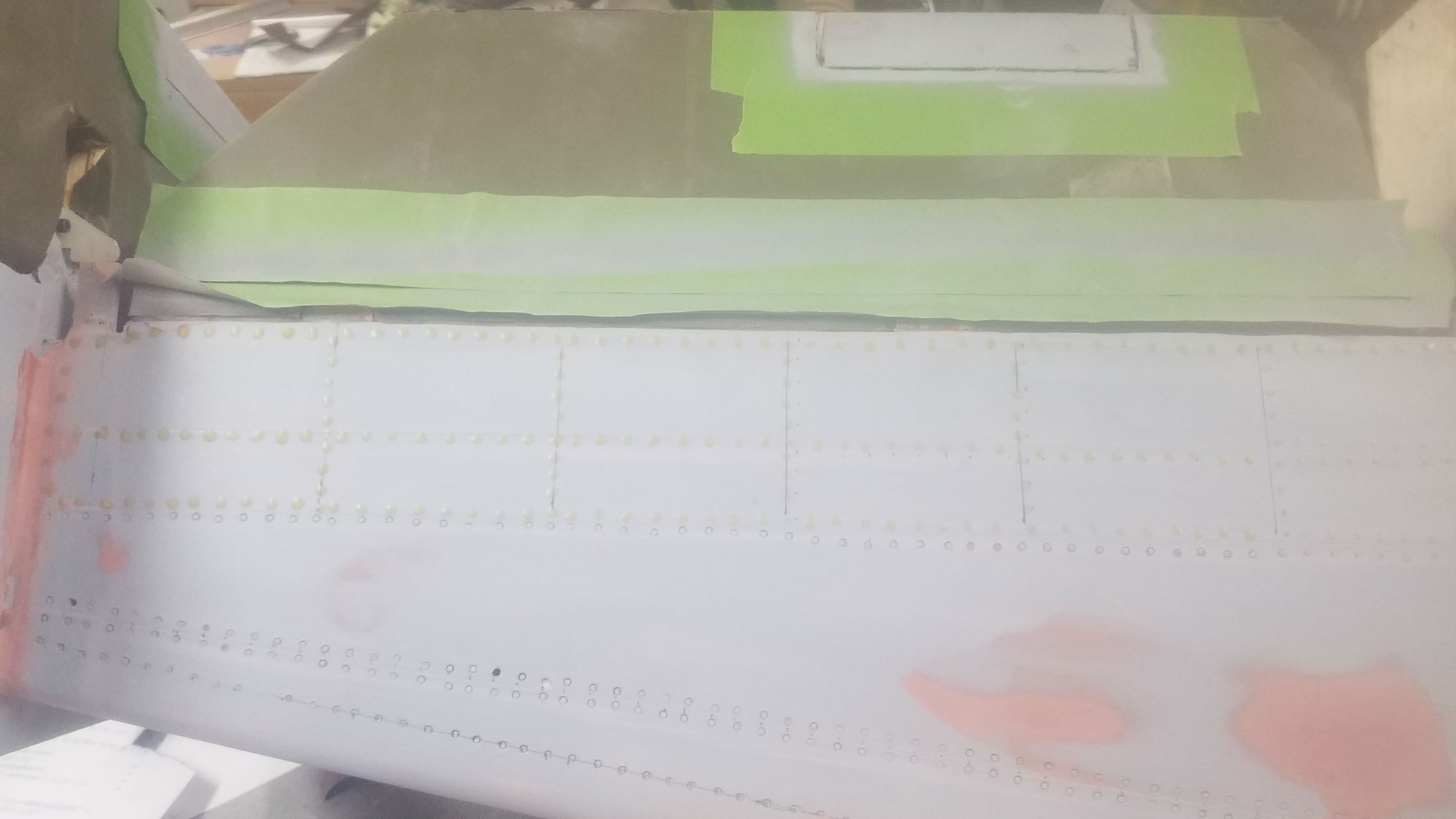
Example of lines drawn on for rivets and their application. Raised rivets were used to speed up and save costs to build the B25.
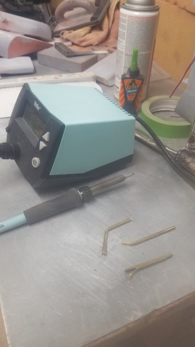
Flush rivet tools. Different attempts of brass tubes to make the rivets.
Flush quarter turn fasteners
Example of quarter turn fasteners on cowl
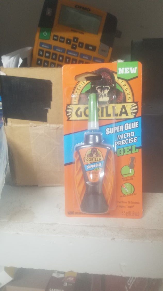
First attempt at raised rivets with glue. Applicator worked well but rivets were too high and large. Rivets needed to be sanded down and, in the process, some got knocked off and had to be replaced.
Applicator opened up and shows how much glue is still left in tube left by the squeeze sides.
Better shot of left over glue in the tube.
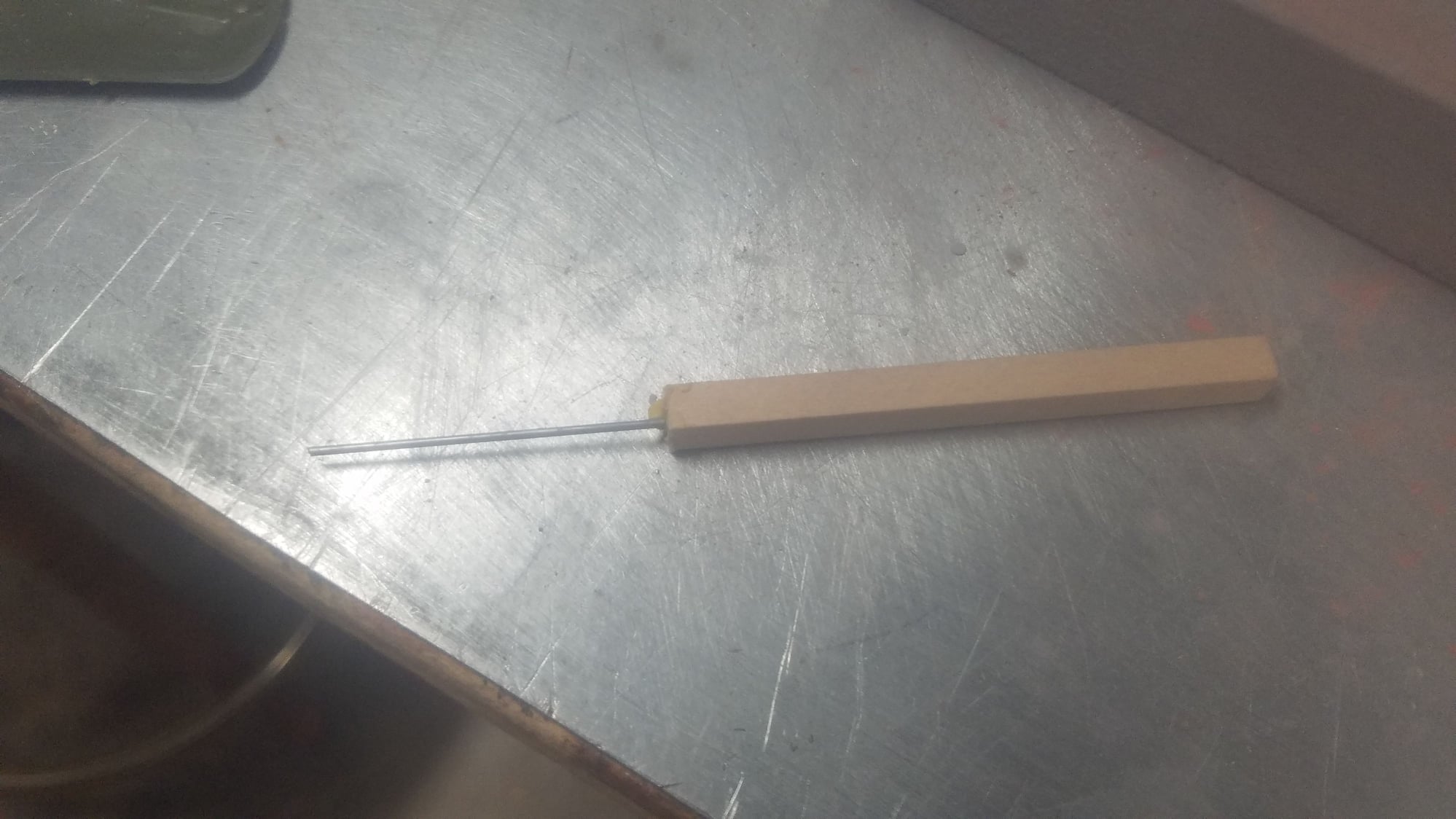
After several attempts to get the correct size for the raised rivet, I made this tool which produced the correct size and height using Titebond white glue dropped in place.
Example of raised rivets.
Example of flush rivets and raised rivet lines drawn on.
Example of raised rivet lines drawn on. Note that all trim tabs on the B25 were metal even if included with a fabric covered structure.
Example of raised rivets lines.
Example of raised rivets.
Example of raised rivets.
Rivets done on horz. stab, but need to be drawn on vert. fins and applied.
Remodeled exhaust ports on the right wing.
Remodeled exhaust vents on the left wing. Needs some more work to finish around the edges.
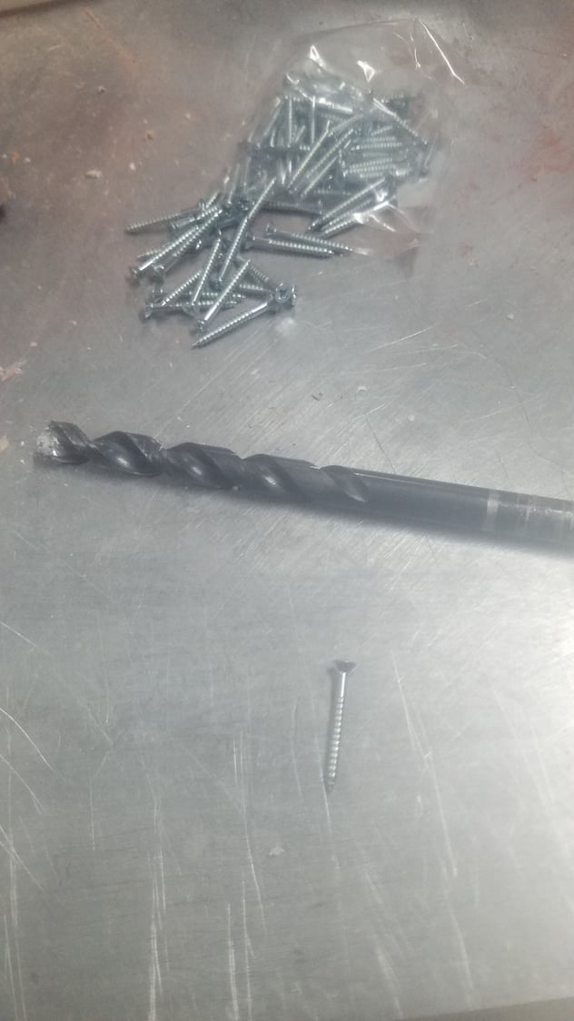
Screws and counter sink for mag cowl attachment reinforcement.
Screws in place.
Screws in place and will have puddy applied to try and hide the screws.
Panel lines on fuselage. Photos don't do a good job at showing the lines.
Panel lines on fuselage
Panel lines and air intakes on center section.
Example of lines drawn on for rivets. The B25 had flush rivets on the first 30 % of the leading edges, then raised rivets for the remainder.
Example of lines drawn on for rivets and their application. Raised rivets were used to speed up and save costs to build the B25.
Flush rivet tools. Different attempts of brass tubes to make the rivets.
Flush quarter turn fasteners
Example of quarter turn fasteners on cowl
First attempt at raised rivets with glue. Applicator worked well but rivets were too high and large. Rivets needed to be sanded down and, in the process, some got knocked off and had to be replaced.
Applicator opened up and shows how much glue is still left in tube left by the squeeze sides.
Better shot of left over glue in the tube.
After several attempts to get the correct size for the raised rivet, I made this tool which produced the correct size and height using Titebond white glue dropped in place.
Example of raised rivets.
Example of flush rivets and raised rivet lines drawn on.
Example of raised rivet lines drawn on. Note that all trim tabs on the B25 were metal even if included with a fabric covered structure.
Example of raised rivets lines.
Example of raised rivets.
Example of raised rivets.
Rivets done on horz. stab, but need to be drawn on vert. fins and applied.
Remodeled exhaust ports on the right wing.
Remodeled exhaust vents on the left wing. Needs some more work to finish around the edges.
Screws and counter sink for mag cowl attachment reinforcement.
Screws in place.
Screws in place and will have puddy applied to try and hide the screws.
Last edited by rossmick; 08-05-2023 at 07:18 AM.
02-04-2024, 11:01 PM
#161
Senior Member
Thread Starter
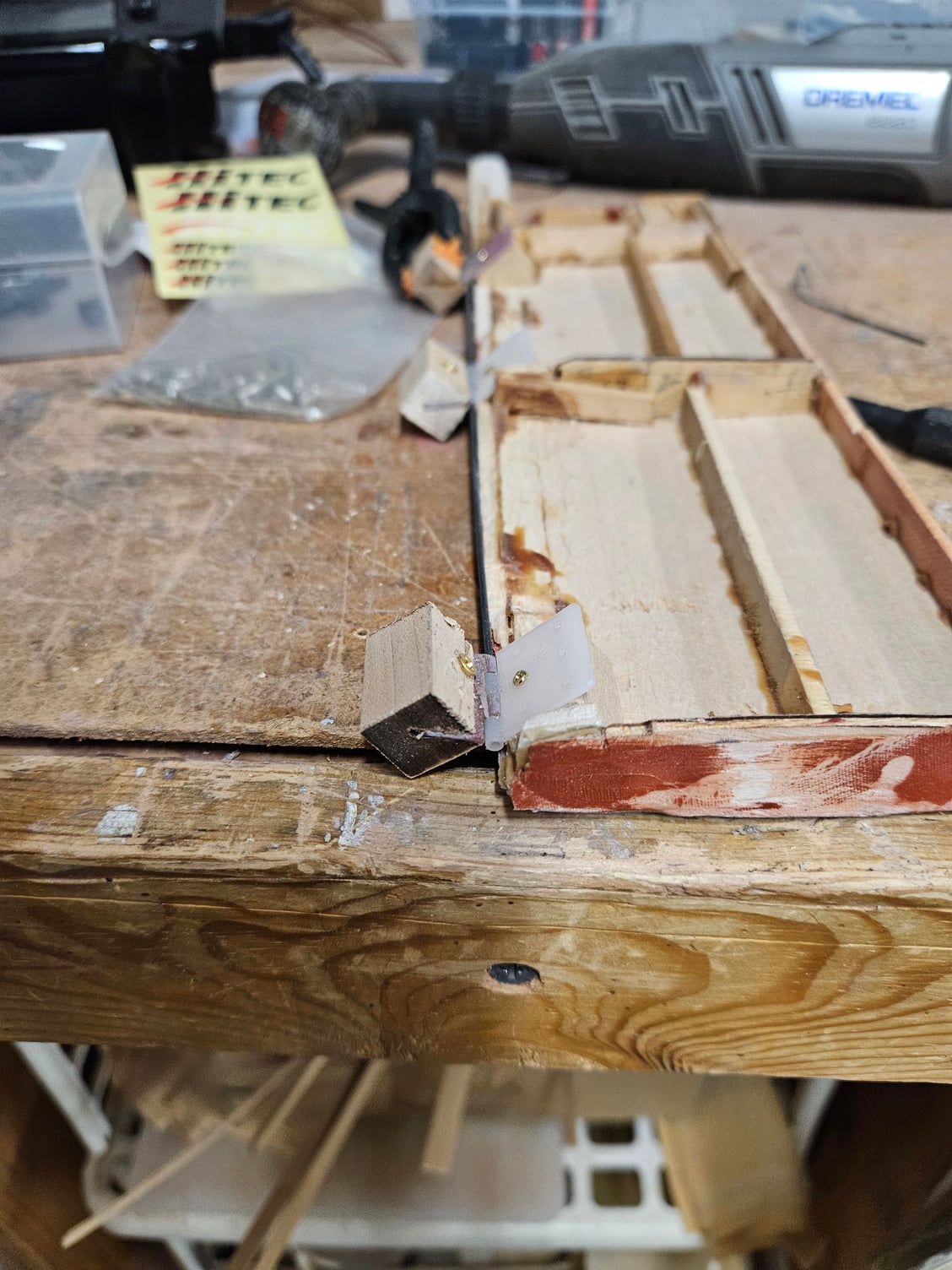
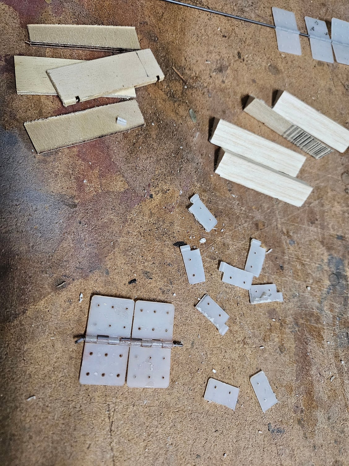
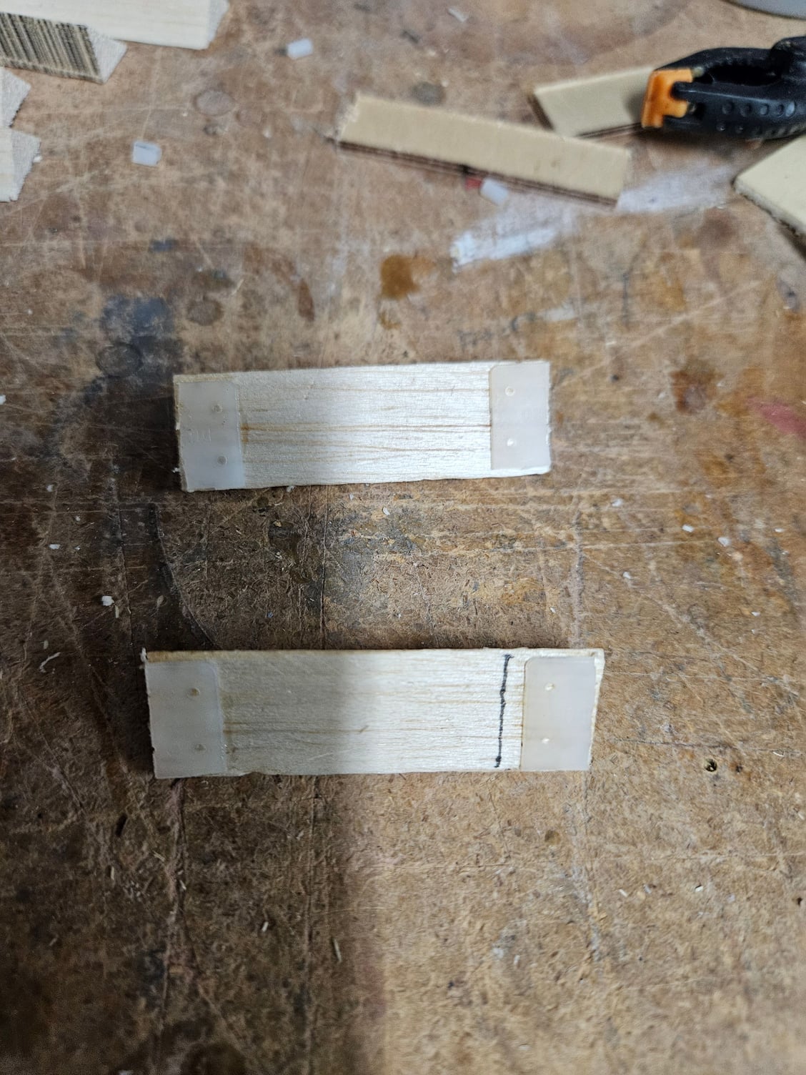
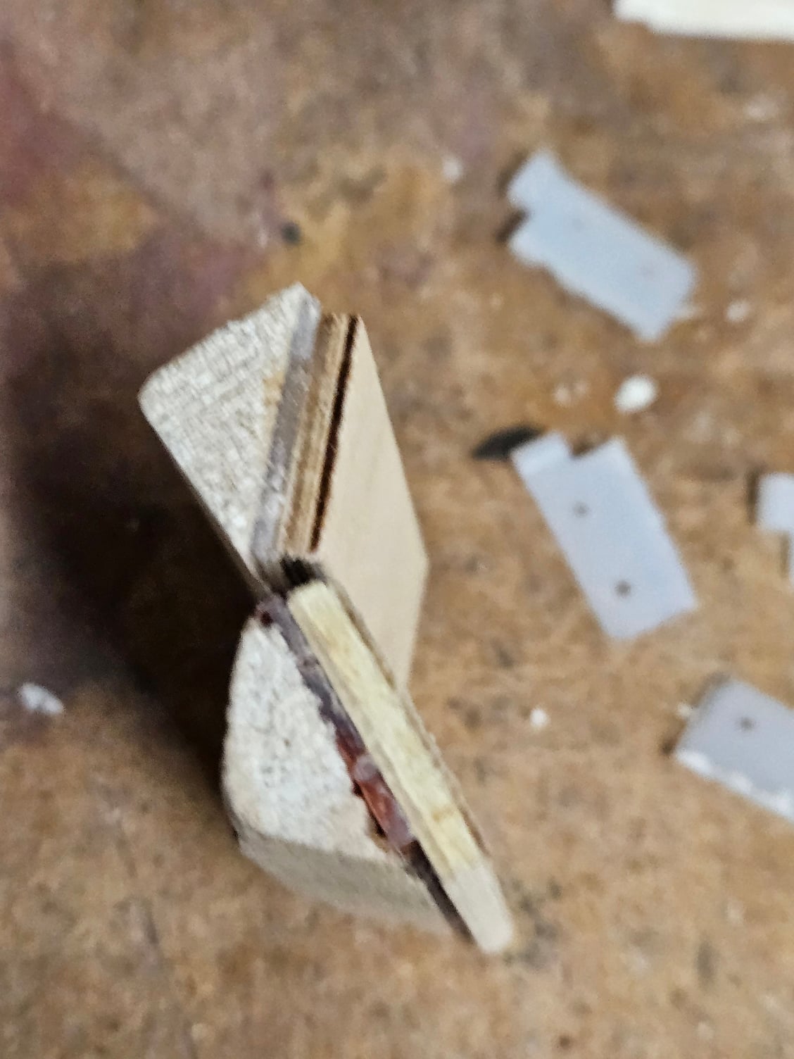
I had to take a break from the B-25 for many reasons least of which was a break from applying rivets (a mind-numbing job). Vacations, the holidays, and other construction projects (carport) for my wife's new car. Got started back mid-January and decided to tackle the hinges for all the doors on the B-25. I have gone through three different versions, but now have come up with what I believe will provide me with the ability to adjust the hinge on install and the ability to remove the hinge due to a damaged door or hinge breakage. I have done a lot of reading on gear door hinging and the big issue was to make sure that they are removable.
The hinge mount is somewhat fussy to build but allows for the hinge to be adjusted in and out to match the outside skin to get a small as possible opening between the door and the body. I also have used an extended hinge pin to help insure a good alignment for all the hinges. One last thing is that I have doubled the amount of hinge at each attach point as my reading also made an issue of hinge breakage due to stress on the hinge when the door gets into the airstream on opening and closing. I will insert two screws on each side of the hinge once it is in the correct position to keep the nylon hinge from pulling out and to hold its position. First two photos are on one idea for a hinge mount. Once installed I could not get to the screws to release the hinge, and it proved to be too weak to stay attached to the skin and the door. 2nd try was with offset hinges that caused a huge opening between the door and the body.
A nylon hinge half was cut in to and glued to the triangle attach member. These keep the nylon hinge from rotating as it is adjusted on install. A plywood face is then glued to the triangle which sets the slot for the nylon hinge to be inserted. I will drill two holes in the ply for the screws to hold each of the hinge sides to keep them from pulling out. Also, I chamfered the ply to allow for the hinge mount to close to a 90-degree position,
Last edited by rossmick; 02-04-2024 at 11:19 PM. Reason: correct photos
