


Ziroli 1/7 (120") B-25 B scale build
 07-16-2022, 07:13 PM
#101
Senior Member
Thread Starter

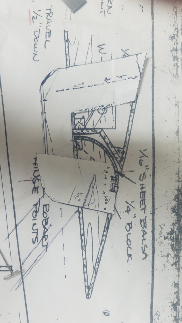
I got my brass tube and Robart hinges installed and found that there was way too much looseness in the flap movement. The brass tubes were not ridged enough and would have allowed the flap to move or flutter in my opinion. This idea would work for a smaller plane, 60 to 80" with smaller flaps, so I will hang on to them for future work. Spent the morning designing a G10 flap hinge. Now it is way over kill on the strength, but I only had .125" material so that is what I will use. I'll bet the flaps will not move now.
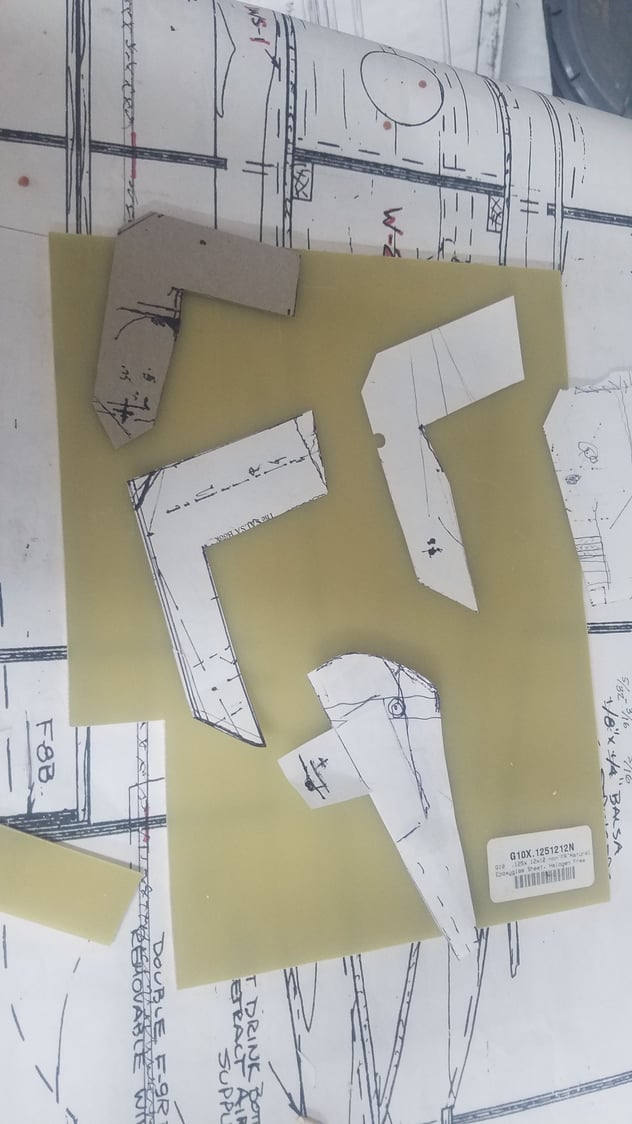
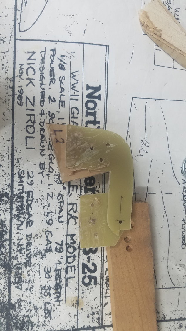
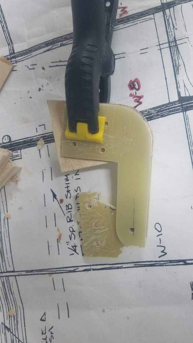
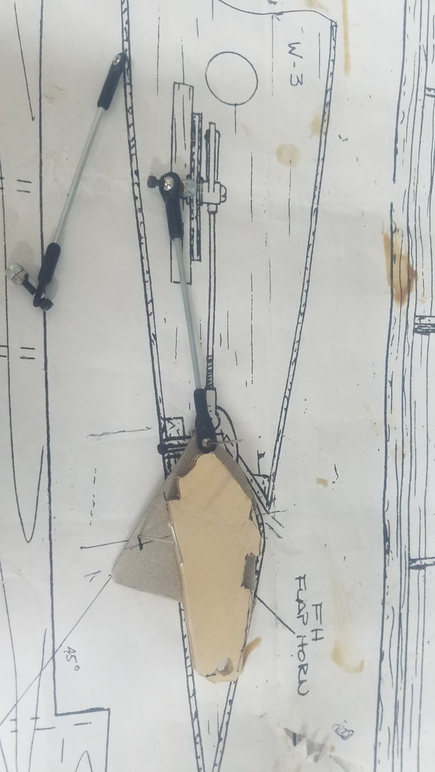
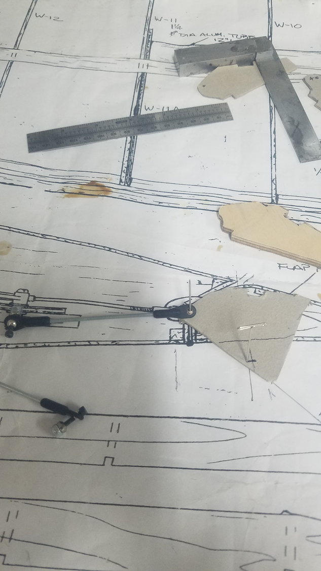
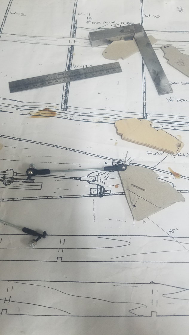
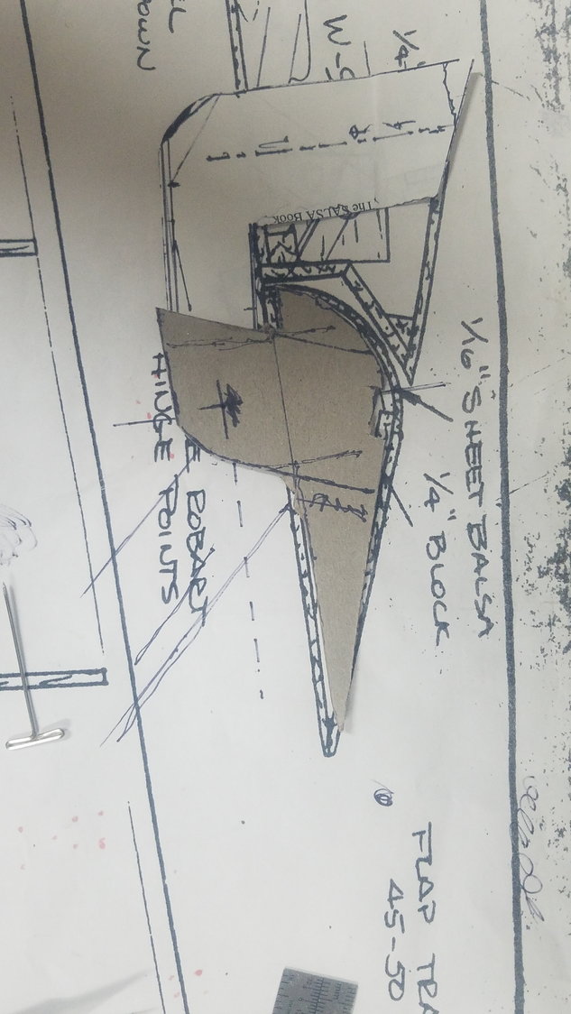
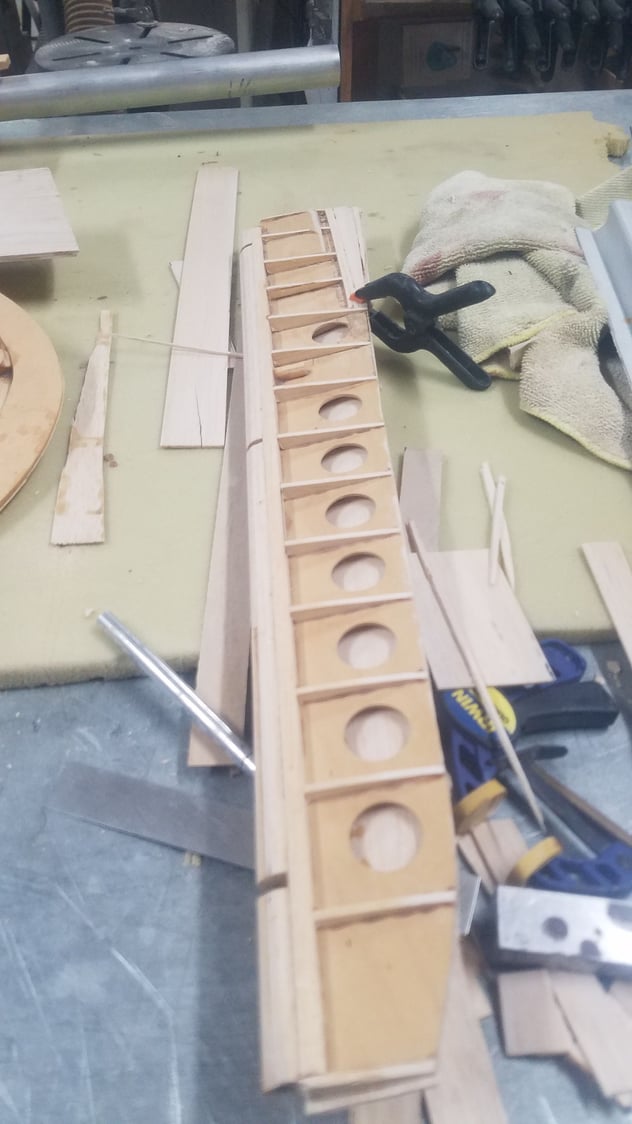
Different template ideas used on the plan to check for proper movement.
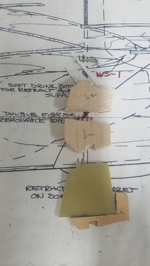
Final design with flap at 45 degrees.
Just cut one hinge setup but looks pretty good. Could only spend the morning working on the project so will pick this up tomorrow.
Mounting blocks not installed but shows basic design. Undecided on G10 section in flap as to how to mount for best strength.
Different template ideas used on the plan to check for proper movement.
Final design with flap at 45 degrees.
Just cut one hinge setup but looks pretty good. Could only spend the morning working on the project so will pick this up tomorrow.
Mounting blocks not installed but shows basic design. Undecided on G10 section in flap as to how to mount for best strength.
 07-17-2022, 08:19 PM
#102
Senior Member
Thread Starter
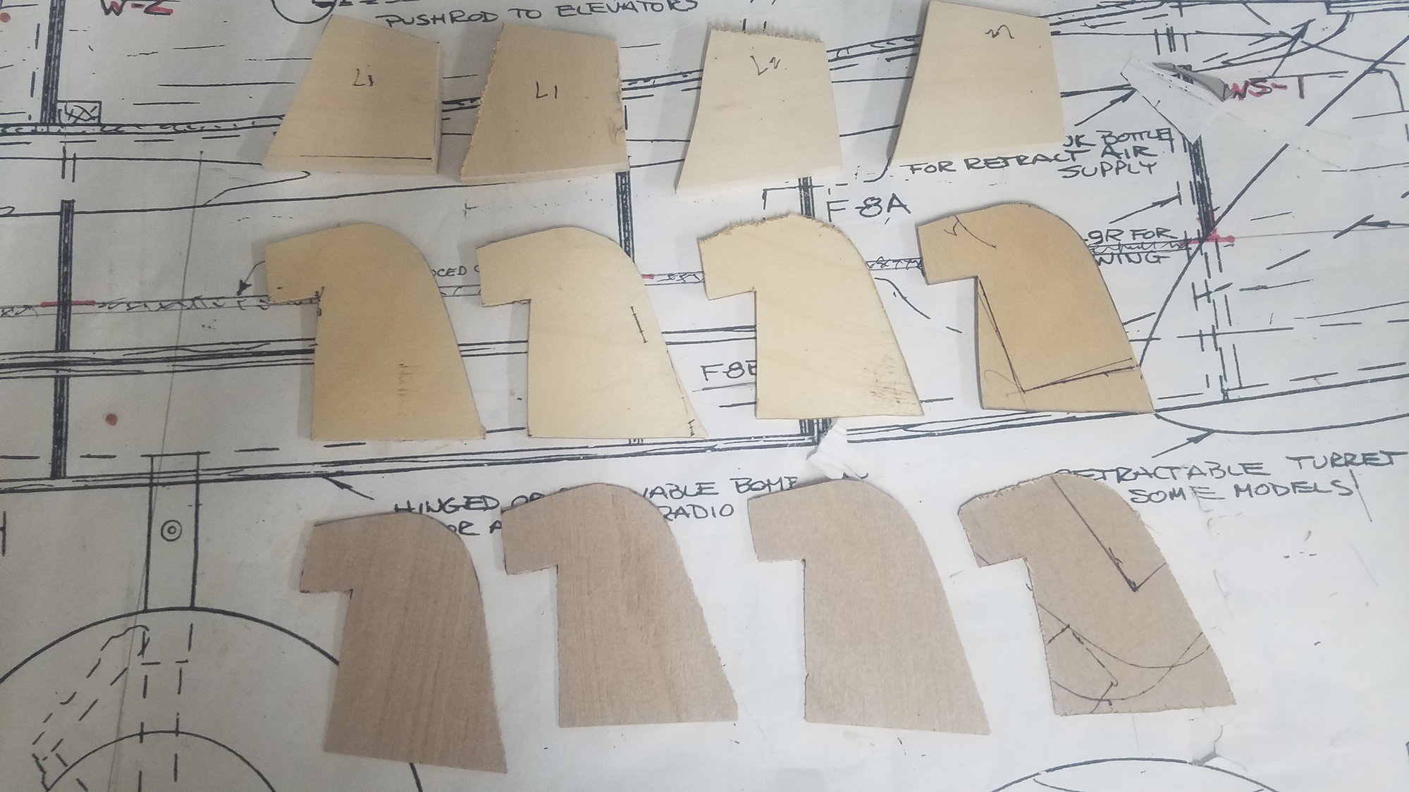
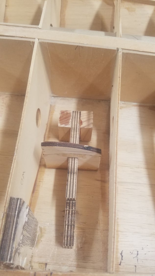
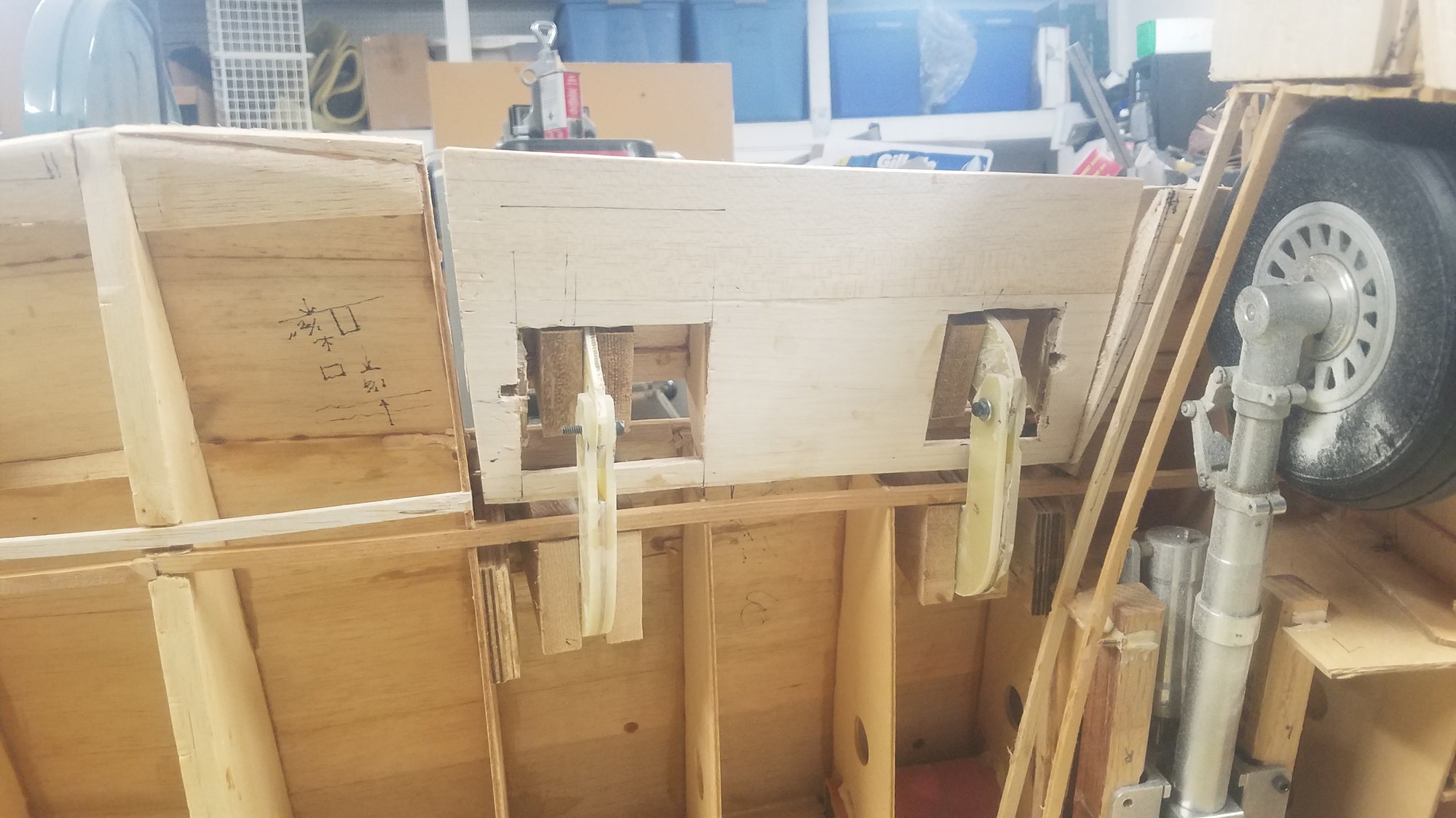
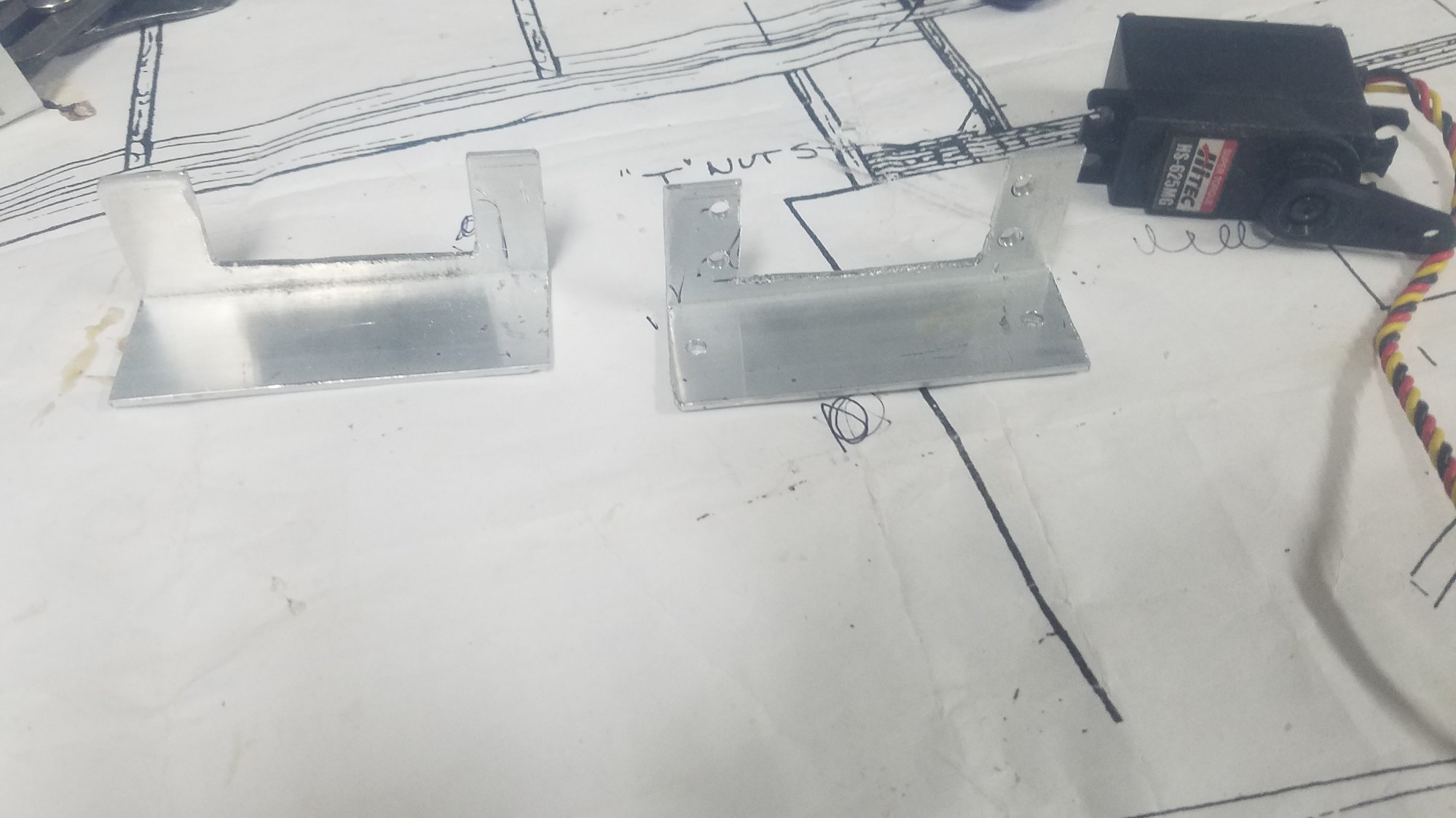
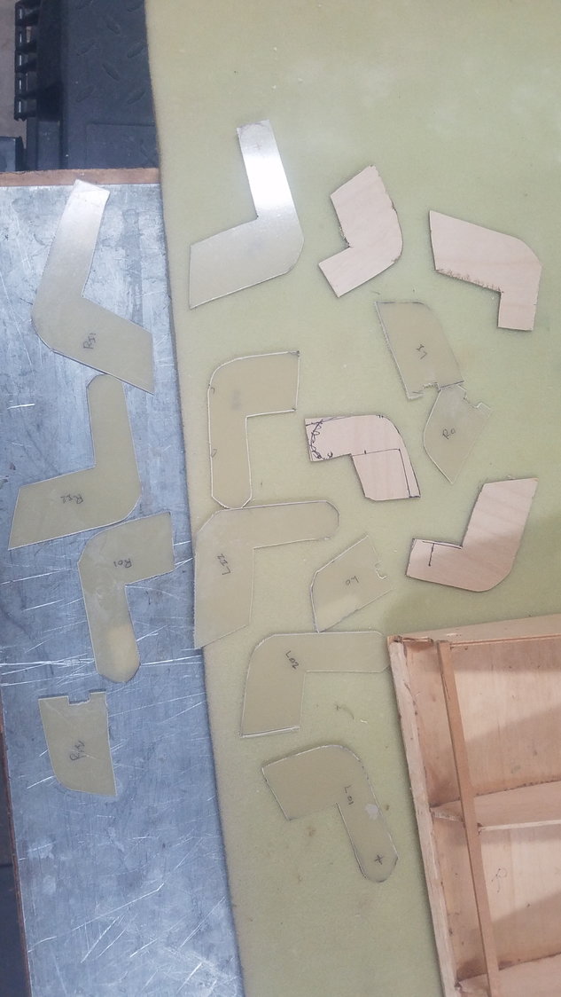
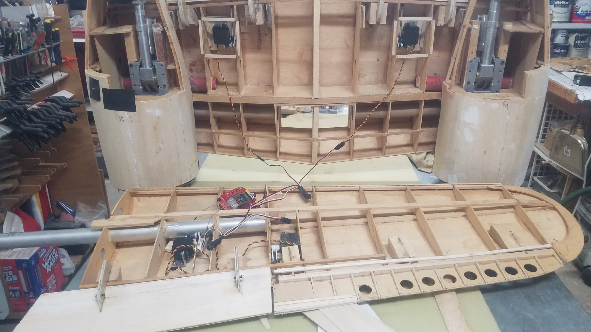
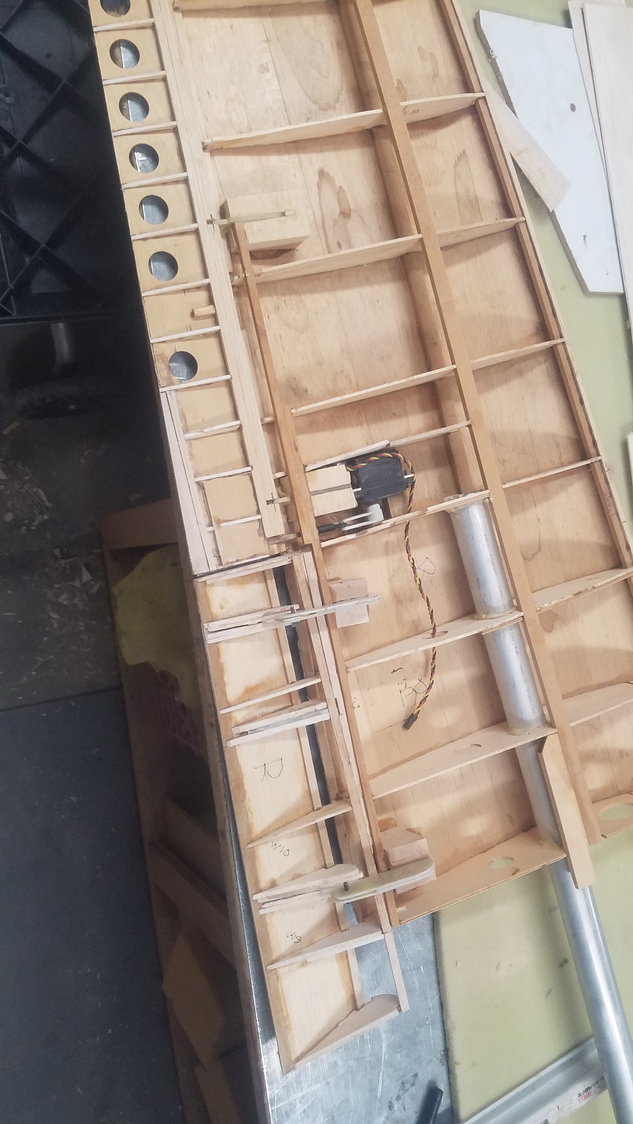
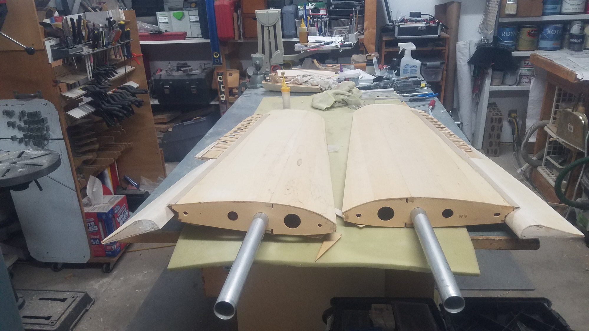
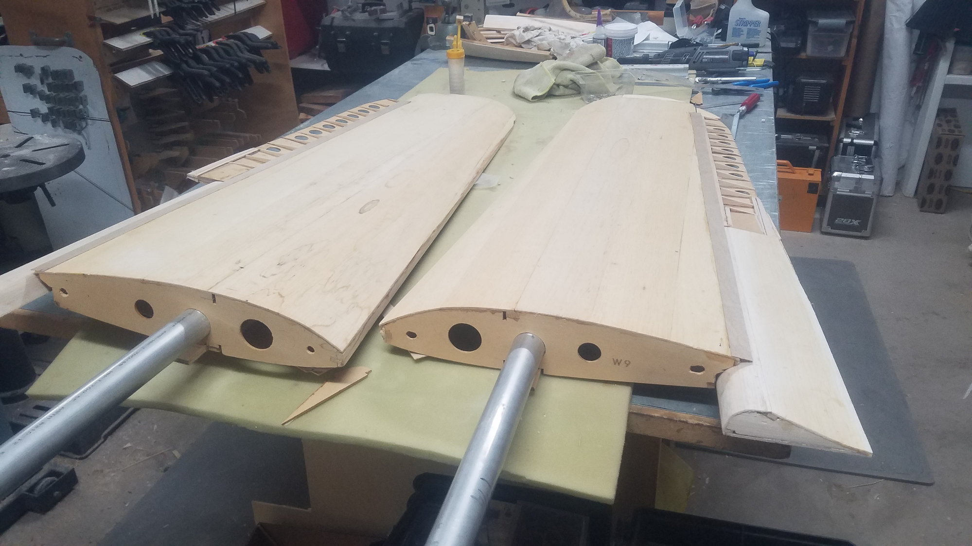
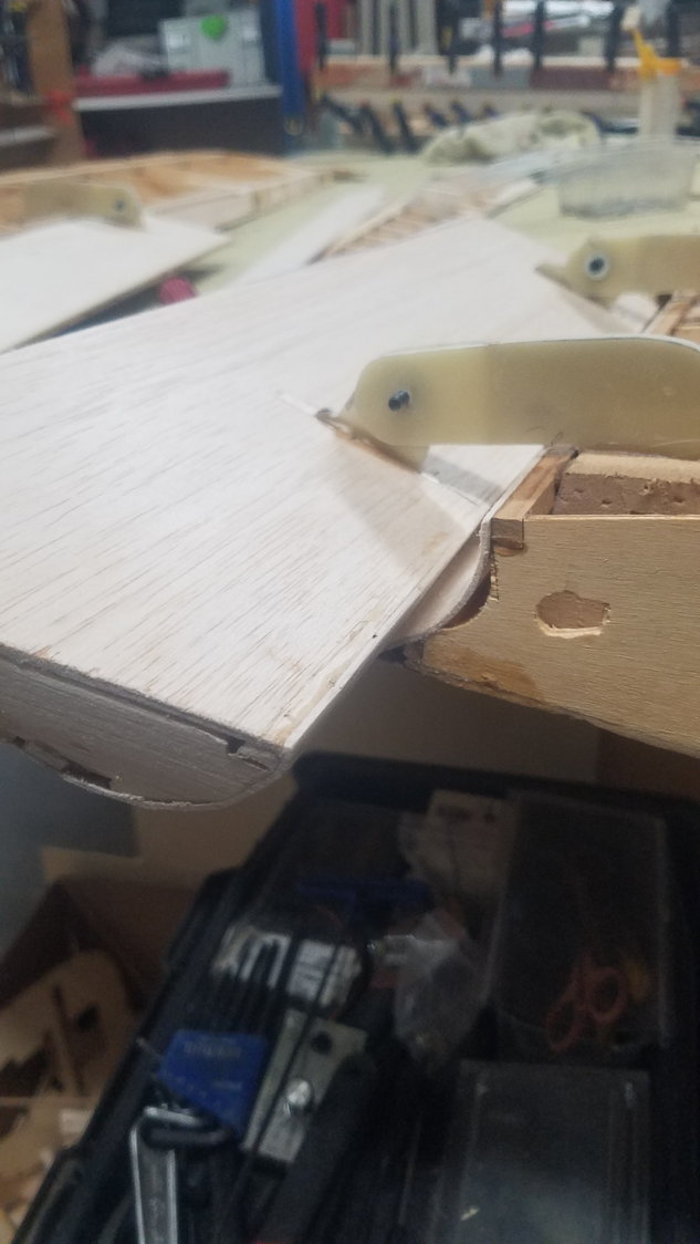
Different parts for the attachments in the wing. I have included a 1/64" shim to open up the 1/8" area so that there is less drag on the hinge when it rotates. Right hand side attachment is slightly smaller than left side.
The different attachment pieces for the flap. Again, right side slightly smaller than the left. This time the hinge will be perpendicular to the flap and not aligned to the rib, that was a mistake on the first attempt with the brass tube design.
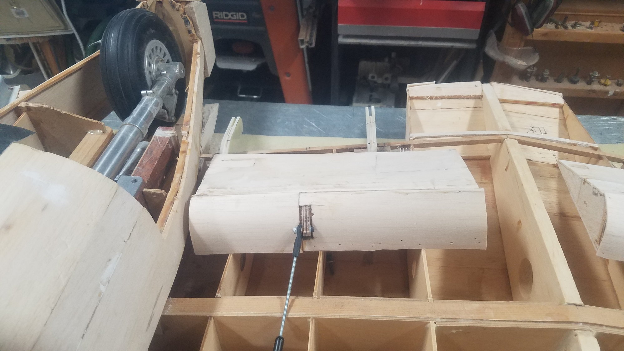
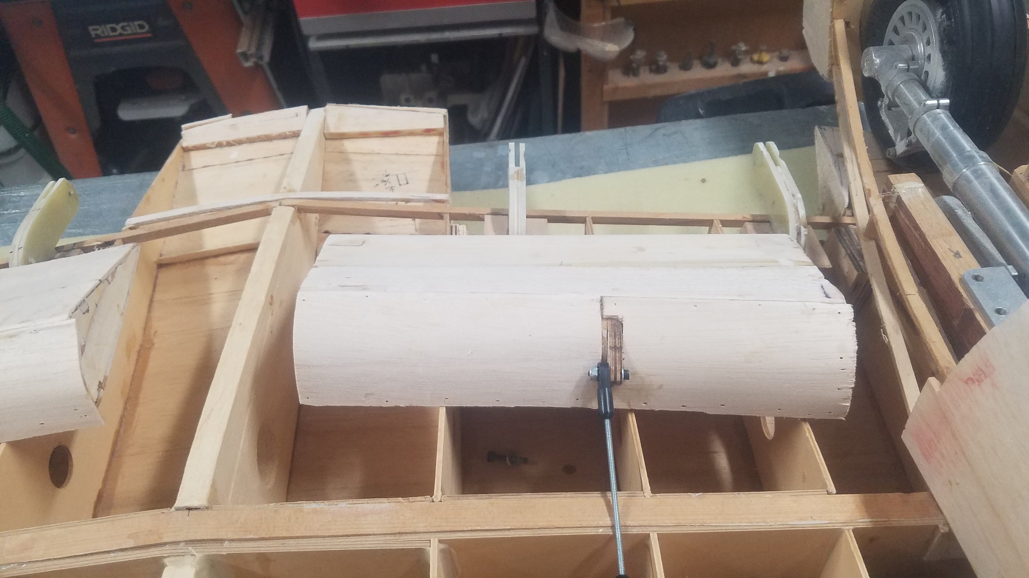
Dry fit without the attachment items in the flap. Will drill for pivot location and install bolt and nylock nut. Had to open skin on the flap to have access to glue in attachment sections. Going flying tomorrow and will pick this up after I get back.
07-18-2022, 07:42 PM
#103
Senior Member
Thread Starter
Flew this morning, on the field by 0700 done by 1000 due to heat and some wind. Had a good time. Flew my modified 84" test bed Stik. It's heavy about 15 lbs., has twin 40cc engine and flies great. It is the test bed for the twin 40's that are going in the B-25.
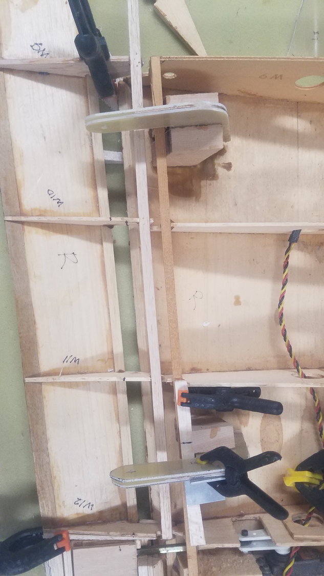
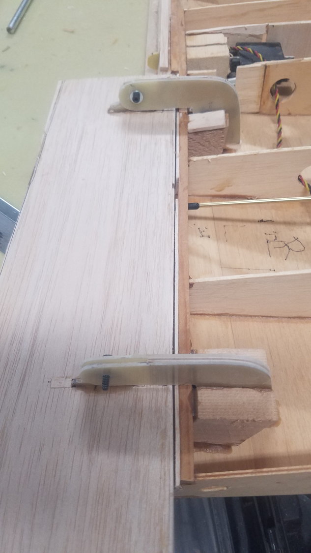
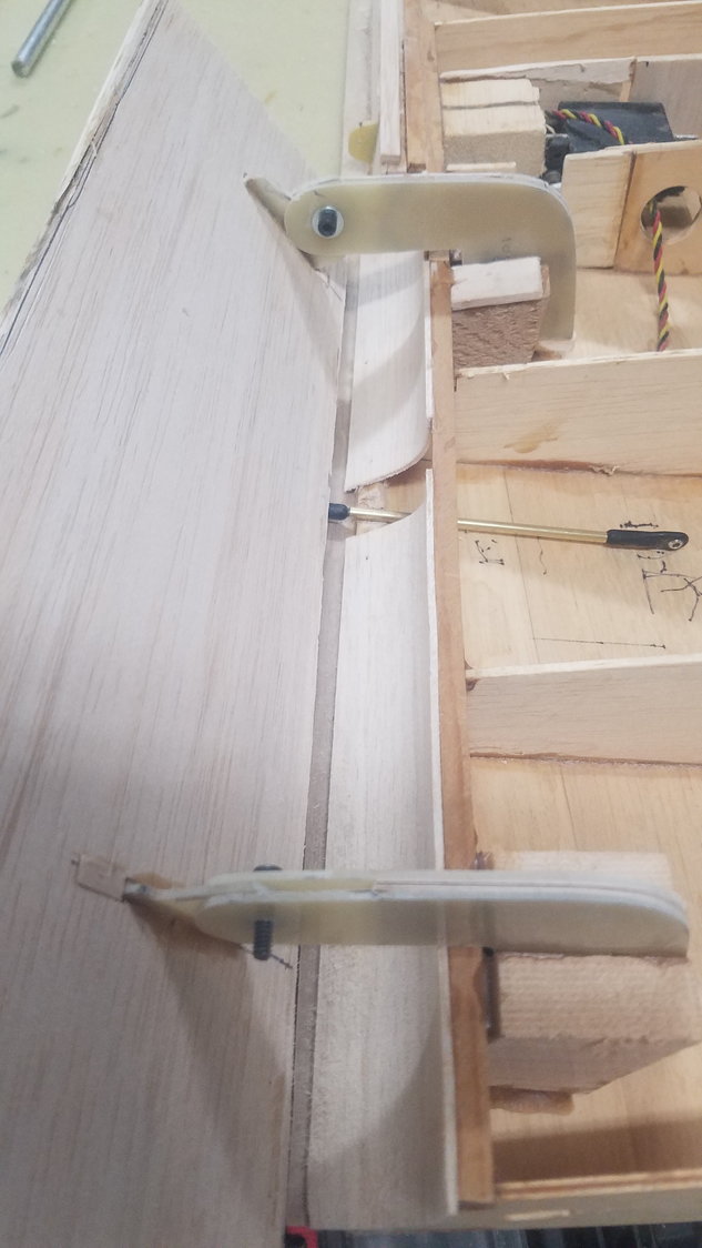
Hinge assembled with #6 bolt with washers and Nylock nut. Holes drilled for glue and surface scraped for better adhesion. Pivot bolt tightened down to stop rotation and then back off about one half turn to allow for easy movement.
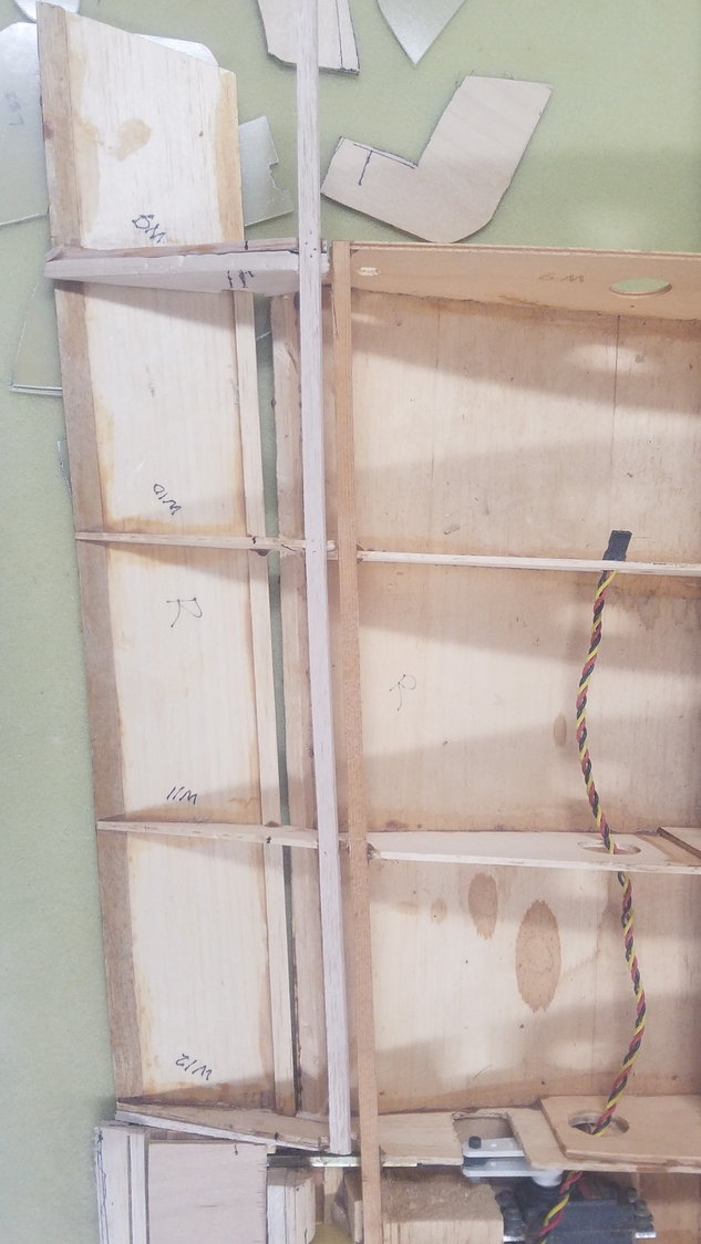
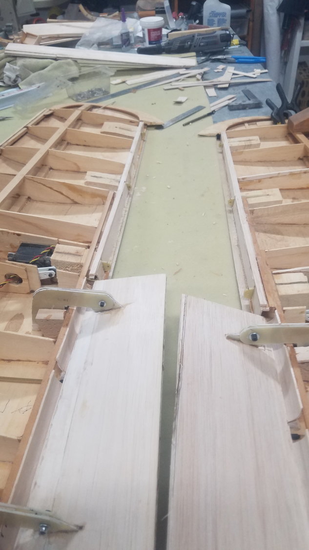
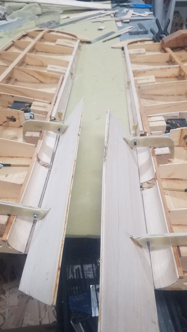
First glue up of hinge on right side flap. Ensuring that the hinge is perpendicular to the flap.
Same setup on the left side flap. Once Tightbond has dried, I will reglue with Aeropoxy on the edges. Sure, was a lot of work getting here.
Hinge assembled with #6 bolt with washers and Nylock nut. Holes drilled for glue and surface scraped for better adhesion. Pivot bolt tightened down to stop rotation and then back off about one half turn to allow for easy movement.
First glue up of hinge on right side flap. Ensuring that the hinge is perpendicular to the flap.
Same setup on the left side flap. Once Tightbond has dried, I will reglue with Aeropoxy on the edges. Sure, was a lot of work getting here.
07-19-2022, 07:33 PM
#104
Senior Member
Thread Starter
Not a great day, as the hinges bind as the flaps are deployed through about 30 degrees. It looks like I was not careful enough when I glued them in. I may have to cut them out and reset them. Biggest issue was that the flap attachments were not plumb, so in a rotation they begin to twist. Flying tomorrow so might not get back to this until Thursday. One good thing, I do think I can use the brass tube hinges for the outboard wing flaps. They laid out pretty well on the plans and the distance is shorter which makes them stronger and there is a lot less flap.
07-20-2022, 04:26 PM
#105
Senior Member
Thread Starter
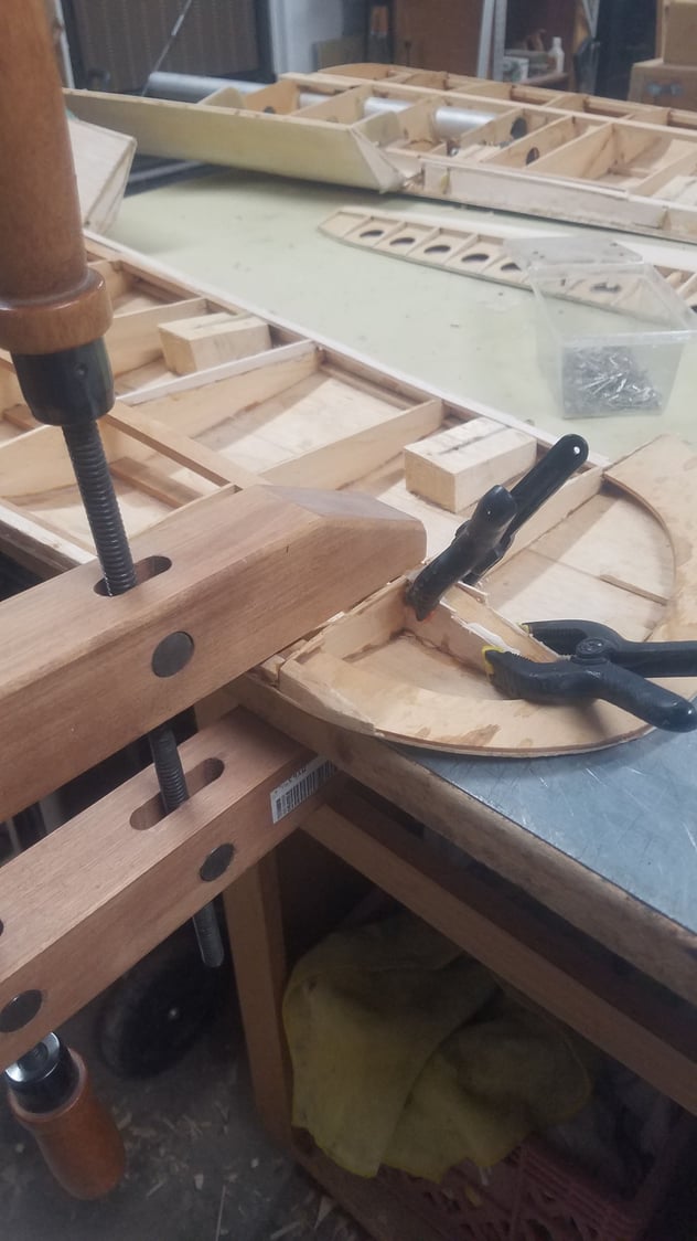
Don't you just hate tearing out what you just put in!! Came out better than I thought, but still have skin to repair or replace. Much more care now in tomorrows and Fridays install. Did not go flying as planned but used the morning to do other items. Got started about 1030 with fear in my heart. Took all afternoon but hinges are out and cleaned up. What a mess! Leason learned, be very careful on installing long reach hinges. Check all alignments and maybe build a dry fit temp assembly to test hinges being square and plum. Be very fussy on the install here. Going flying tomorrow morning at 0630 due to heat so won't get back to this until the afternoon.
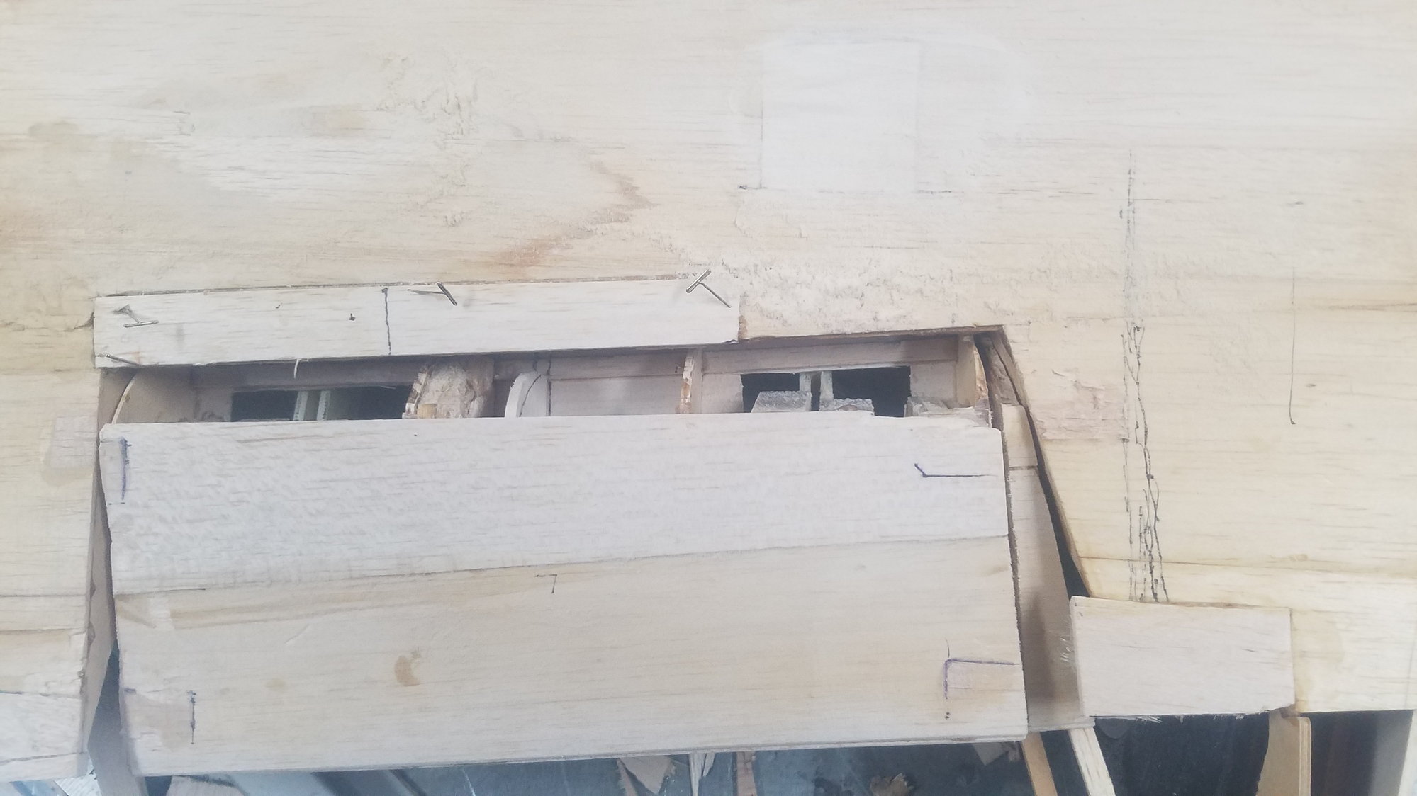
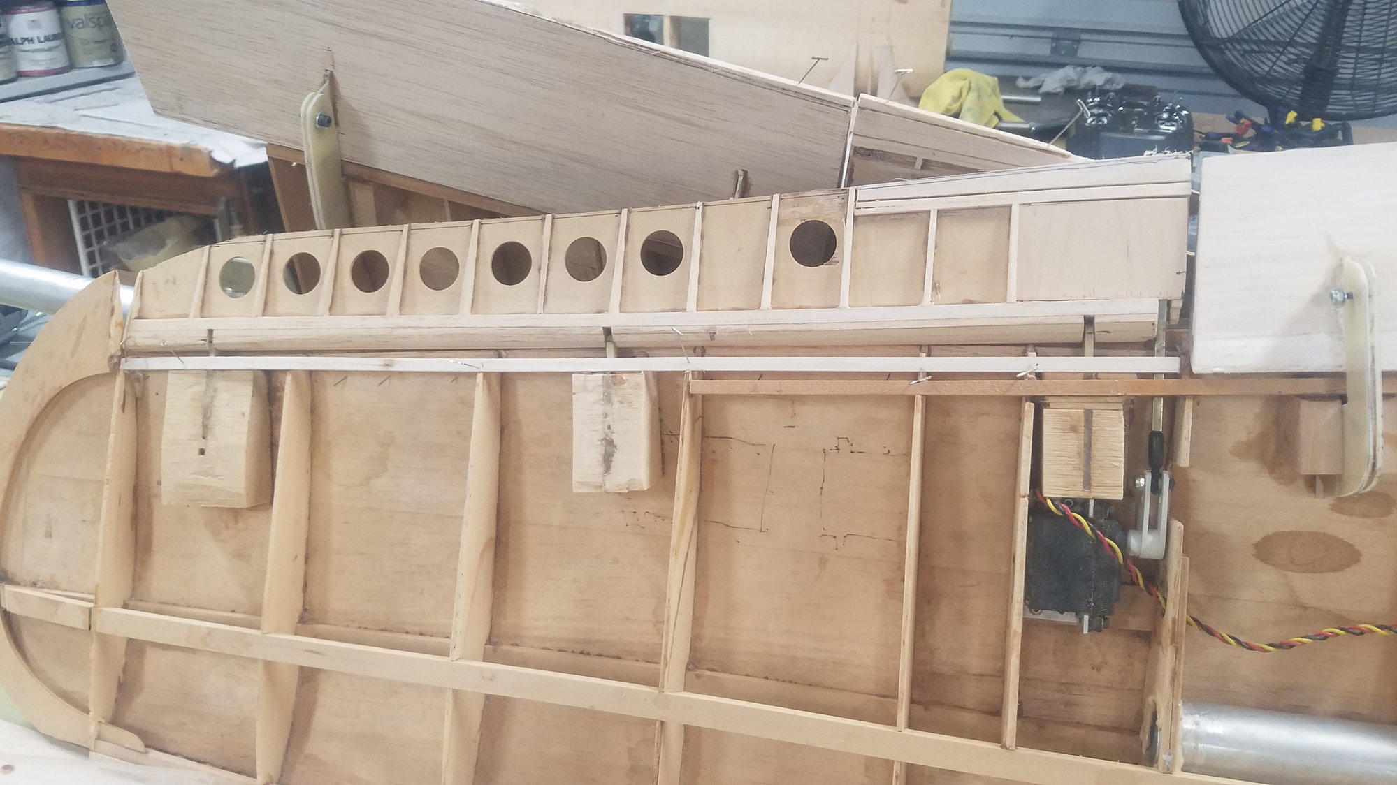
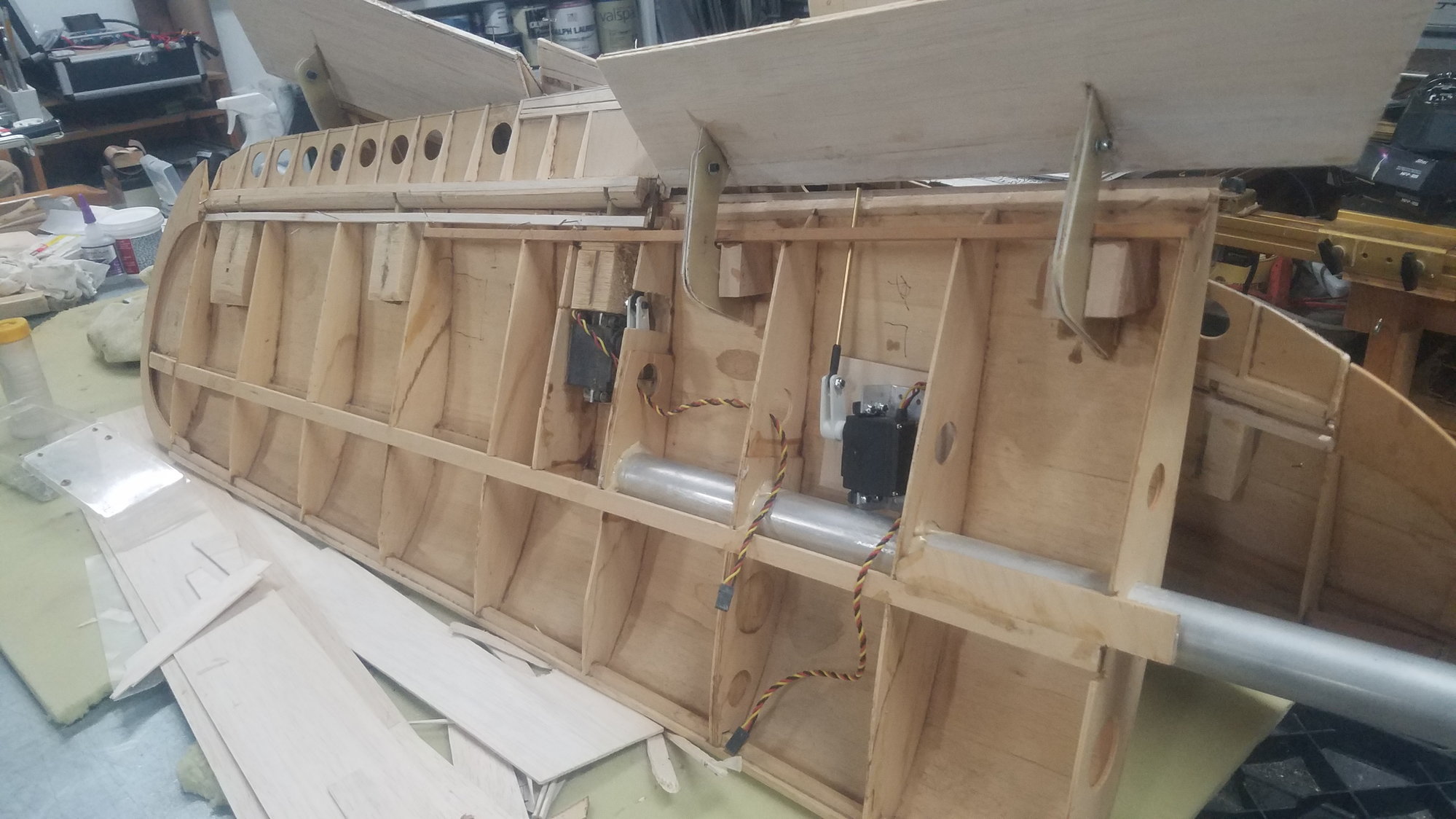
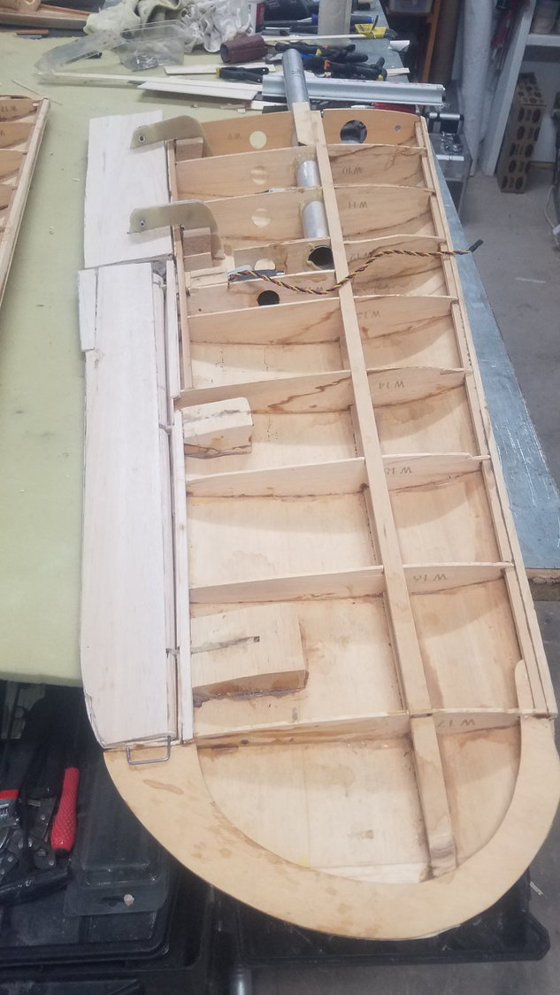
Right side with hinges and support material removed. This is a real pain to do.
Left side removed but damaged the skin getting it all out. Will patch the skin after install is complete.
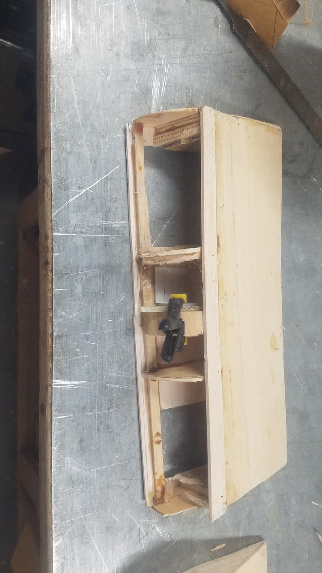
Flap with all hinge items removed including the servo linkage attach point, it was not installed perpendicular or plumb to the flap. Some skin replaced
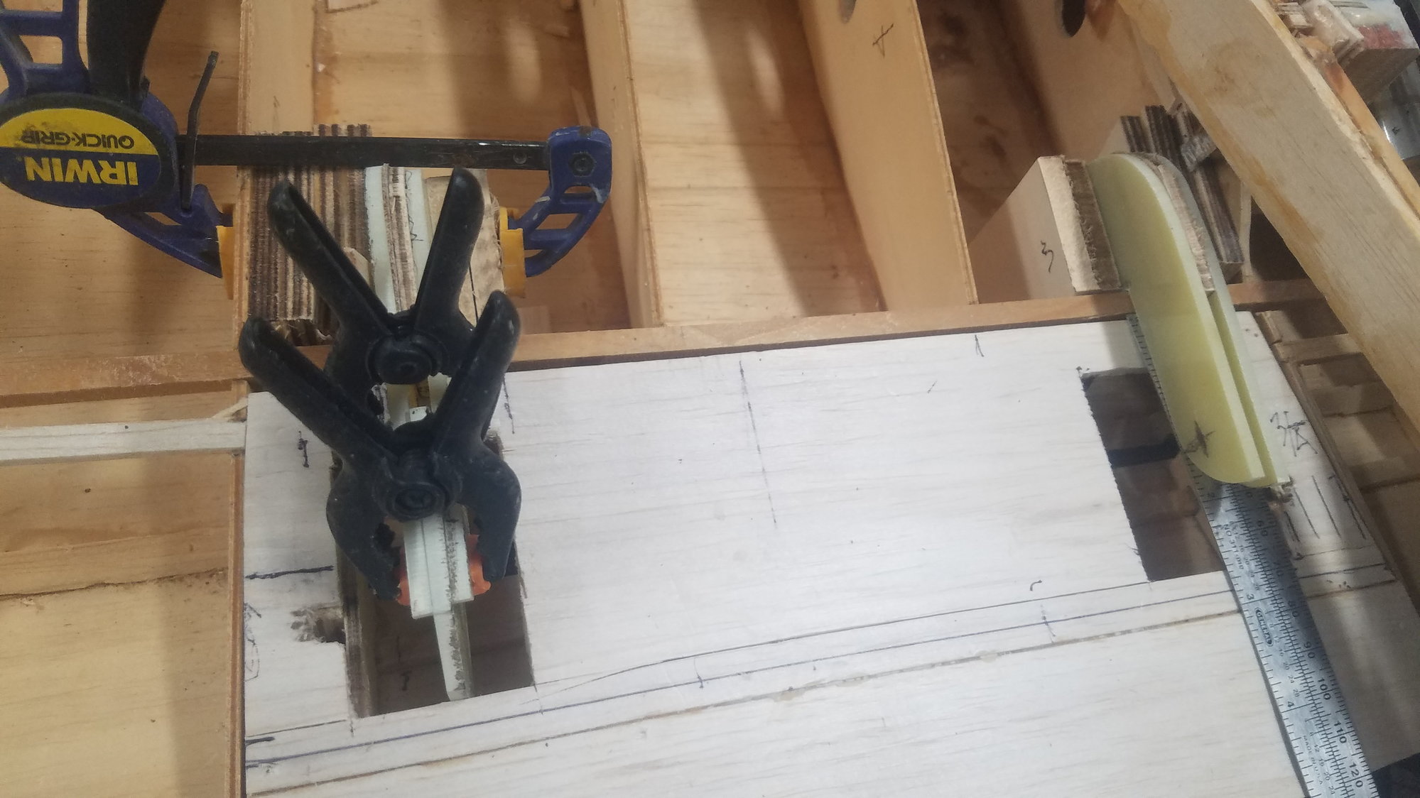
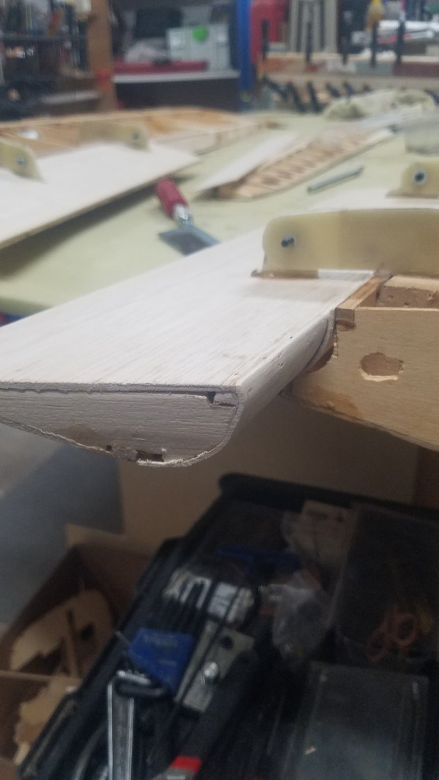
Better shot of dry fit new linkage attach point with 1/2" mounting material and my made-up square to make it plumb. Large area of skin replaced getting stuff removed this time.
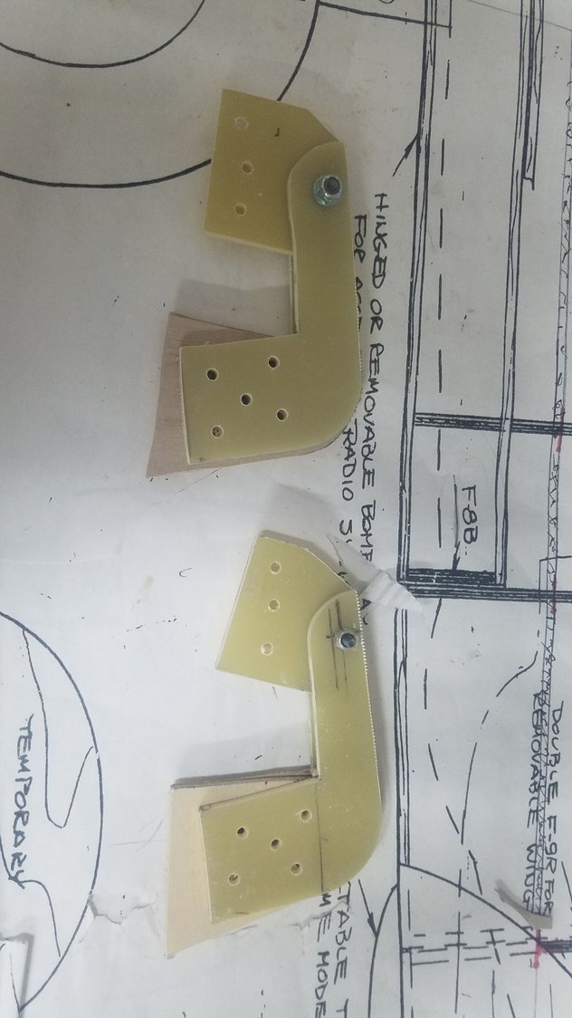
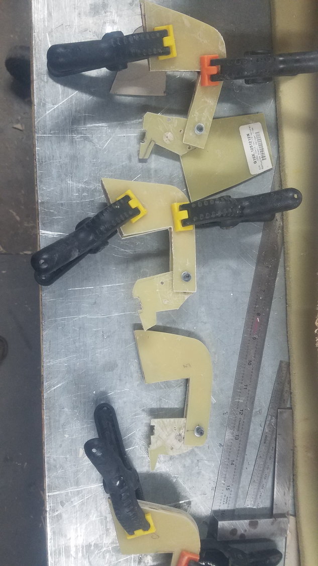
Hinge cleaned and ready for reinstall. It's got to be correct this time.
One other hinge ready to go. I think I will tack weld the G10 in place with Aeropoxy making sure of the alignment, let it sit overnight and then install the blocking with more Aeropoxy. Bad thing is that the hinge structure will not be able to be removed without destroying much more material by using Aeropoxy. Did I mention, it's got to be correct this time.
Right side with hinges and support material removed. This is a real pain to do.
Left side removed but damaged the skin getting it all out. Will patch the skin after install is complete.
Flap with all hinge items removed including the servo linkage attach point, it was not installed perpendicular or plumb to the flap. Some skin replaced
Better shot of dry fit new linkage attach point with 1/2" mounting material and my made-up square to make it plumb. Large area of skin replaced getting stuff removed this time.
Hinge cleaned and ready for reinstall. It's got to be correct this time.
One other hinge ready to go. I think I will tack weld the G10 in place with Aeropoxy making sure of the alignment, let it sit overnight and then install the blocking with more Aeropoxy. Bad thing is that the hinge structure will not be able to be removed without destroying much more material by using Aeropoxy. Did I mention, it's got to be correct this time.
07-21-2022, 04:21 PM
#106
Senior Member
Thread Starter
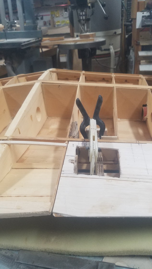
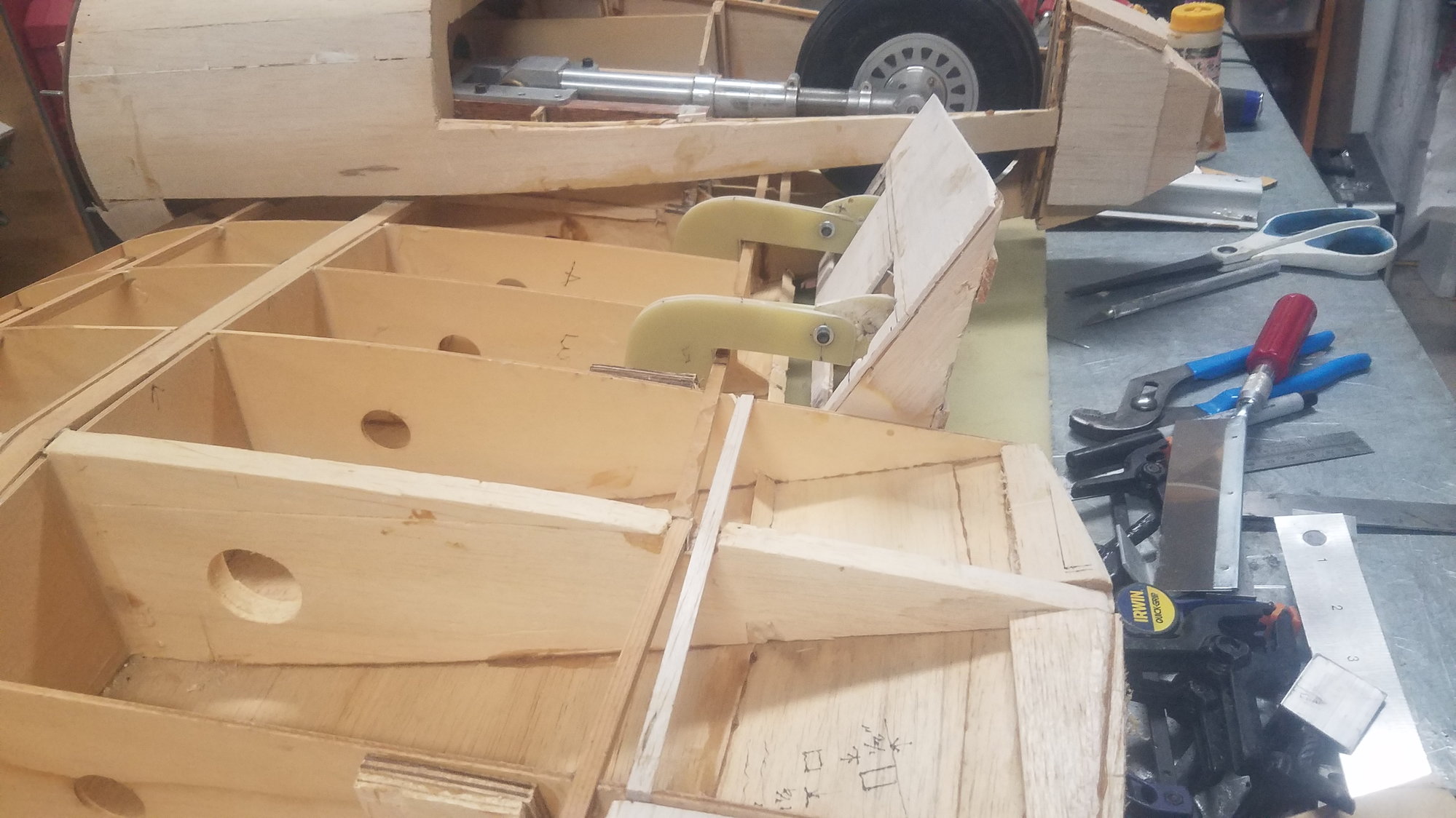
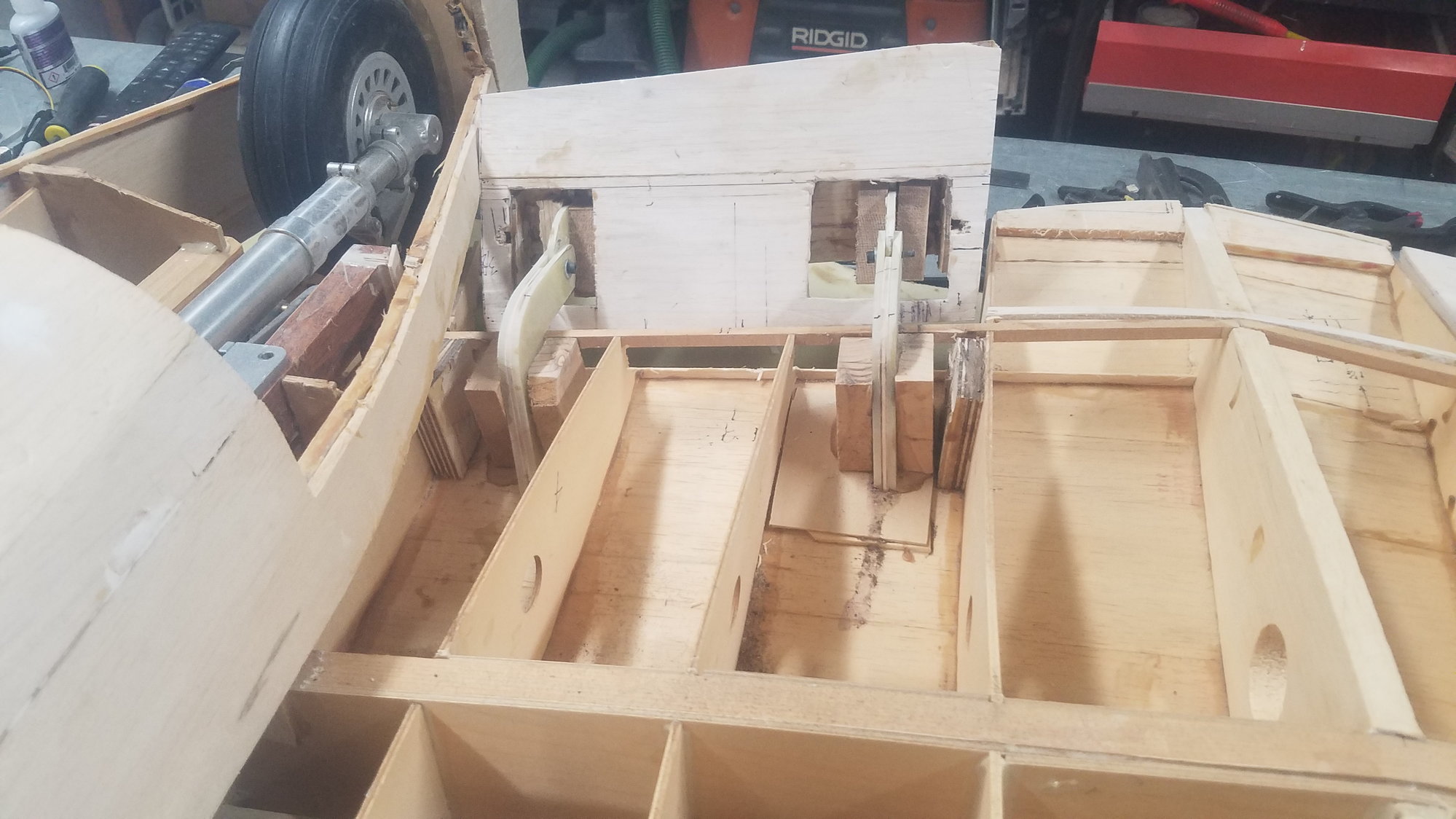
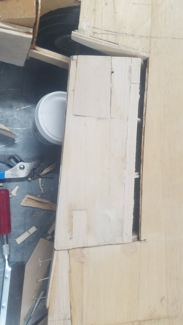
Today I spent some time figuring out just how I was going to improve the layout of the flap hinges. After mulling around for a hour or so, I recalled Sam Parfitt's 2011 build of the B-25 and found the section on how he installed the flaps. Sam, in my opinion, is a master builder and now I see myself using more and more of his building techniques. If you wish to see an absolutely outstanding build here is his address on RCU -- ZIROLI 120" B-25 MITCHELL - RCU Forums (rcuniverse.com). So I did what he did by temporarily gluing the flaps back into place. Now, how do I make the layout work, I will make an effective jig that sets alignment to the flaps.
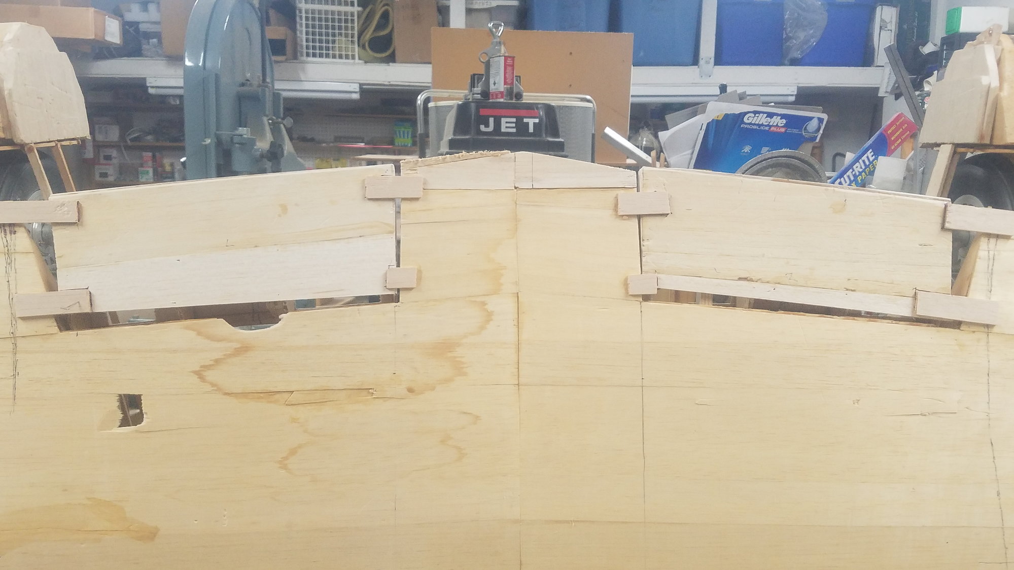
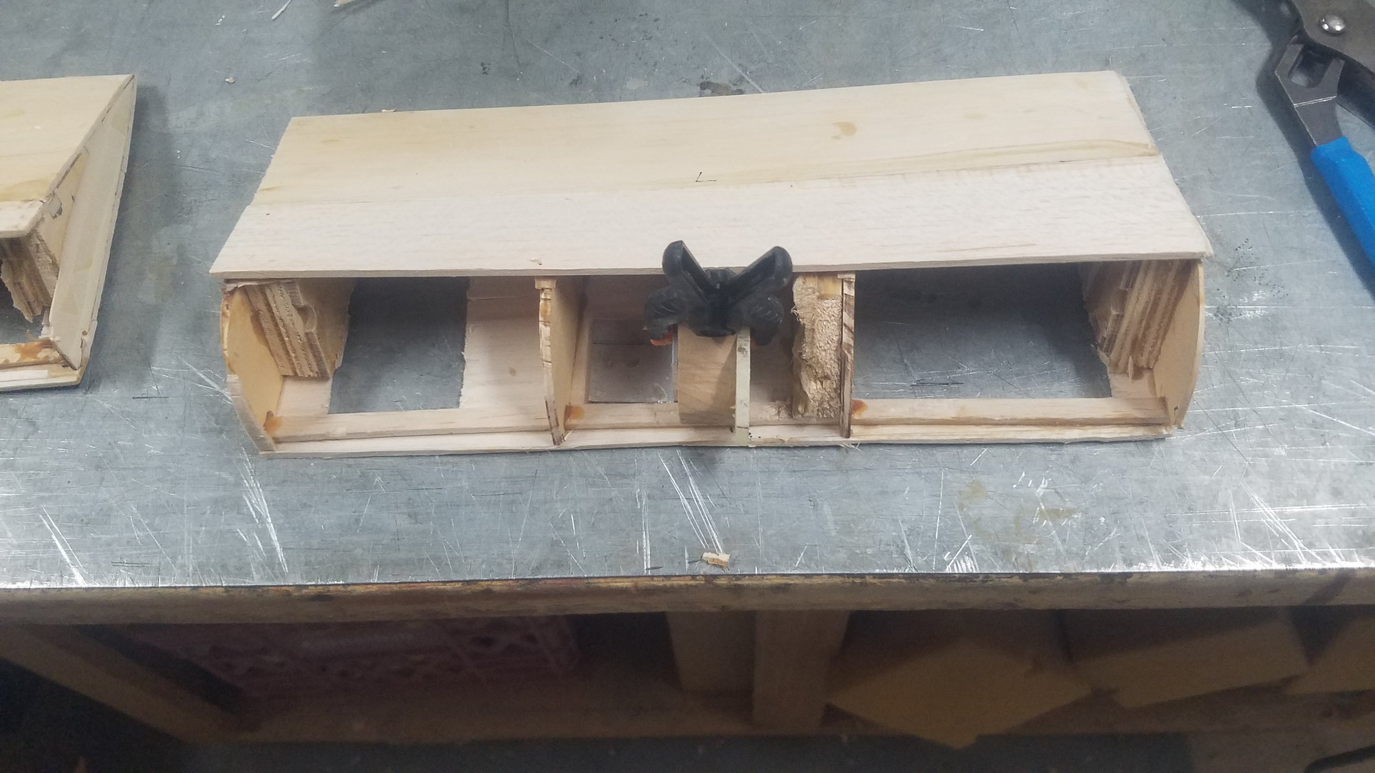
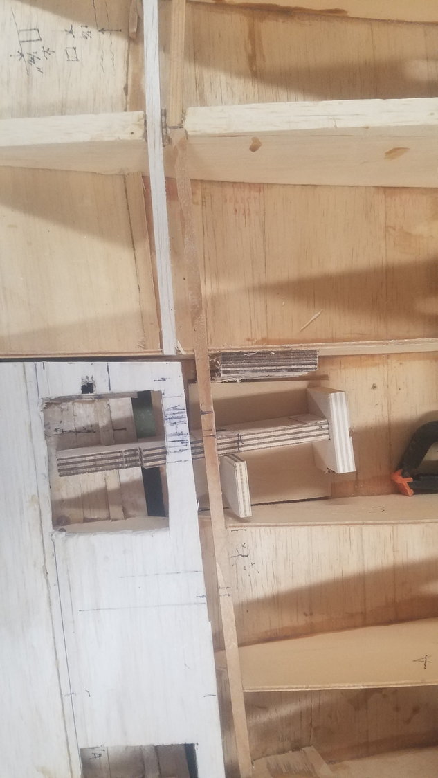
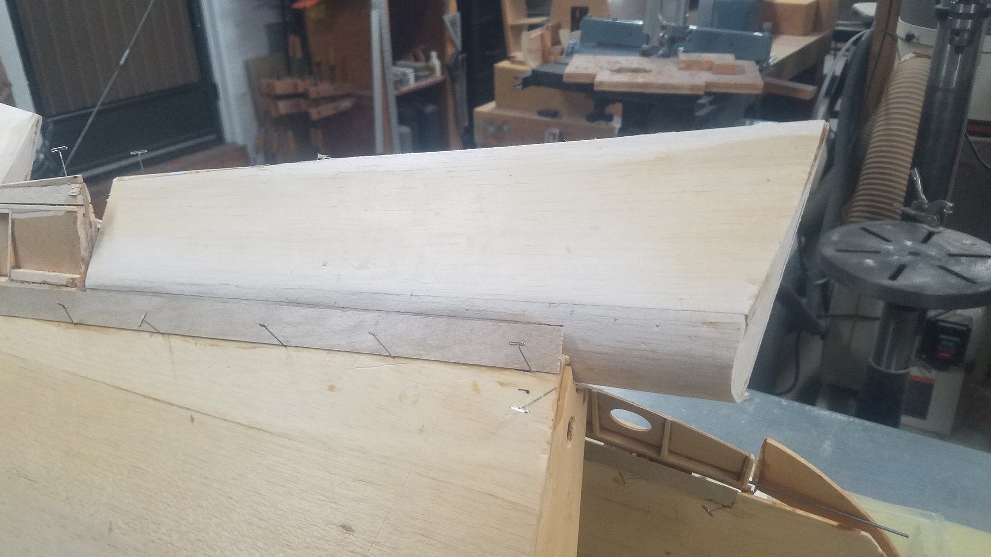
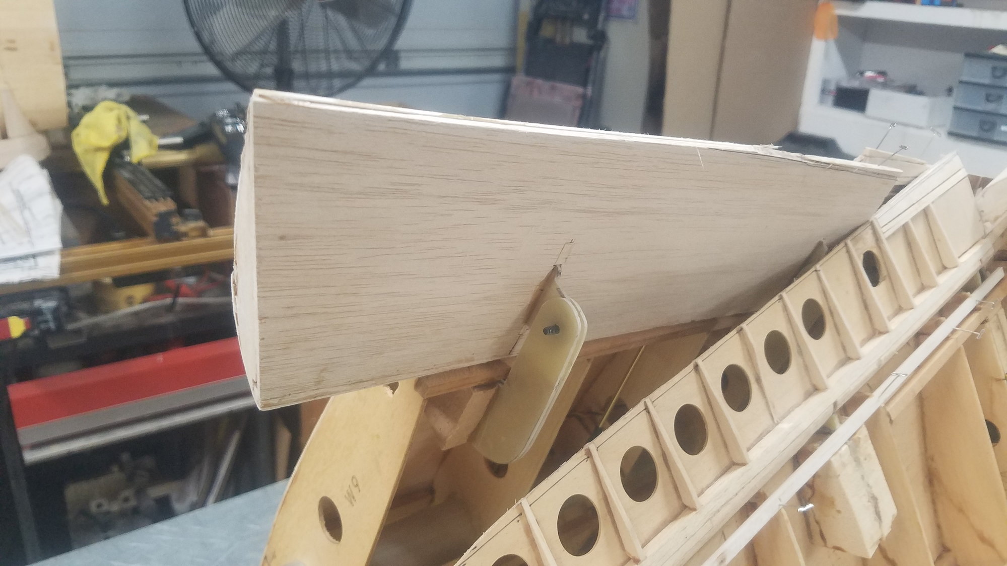
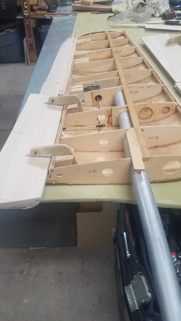
As Sam showed, I went ahead and temporarily glued in the flaps. Also shows how I butchered up the flaps and how much work it will be to get the back in shape.
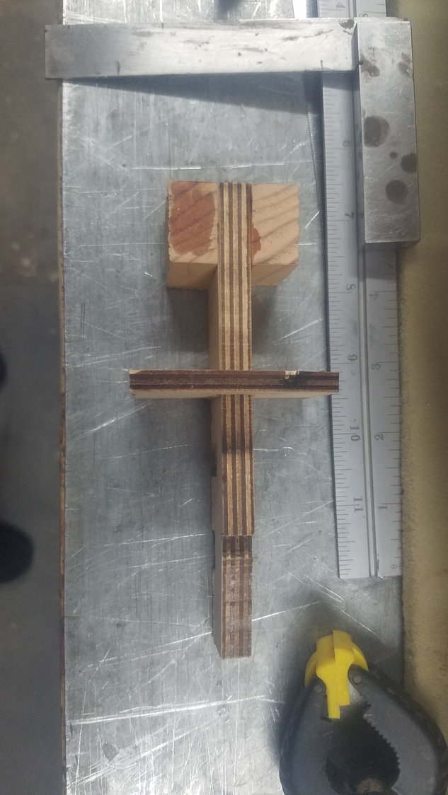
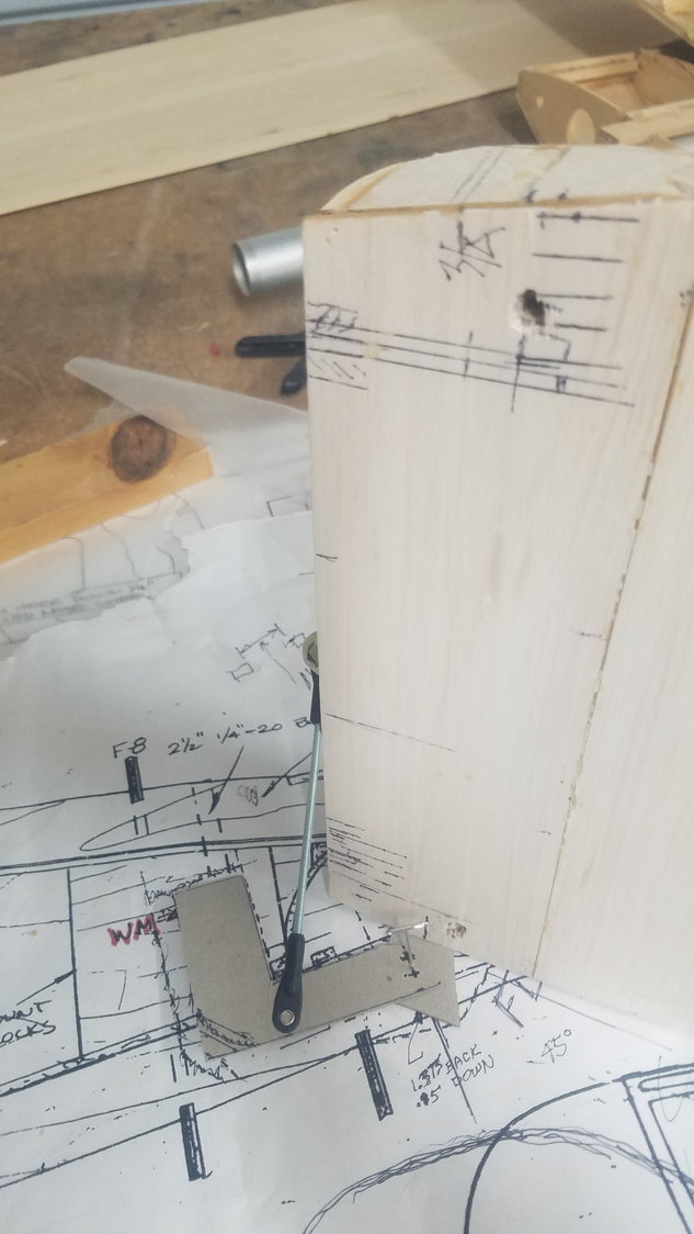
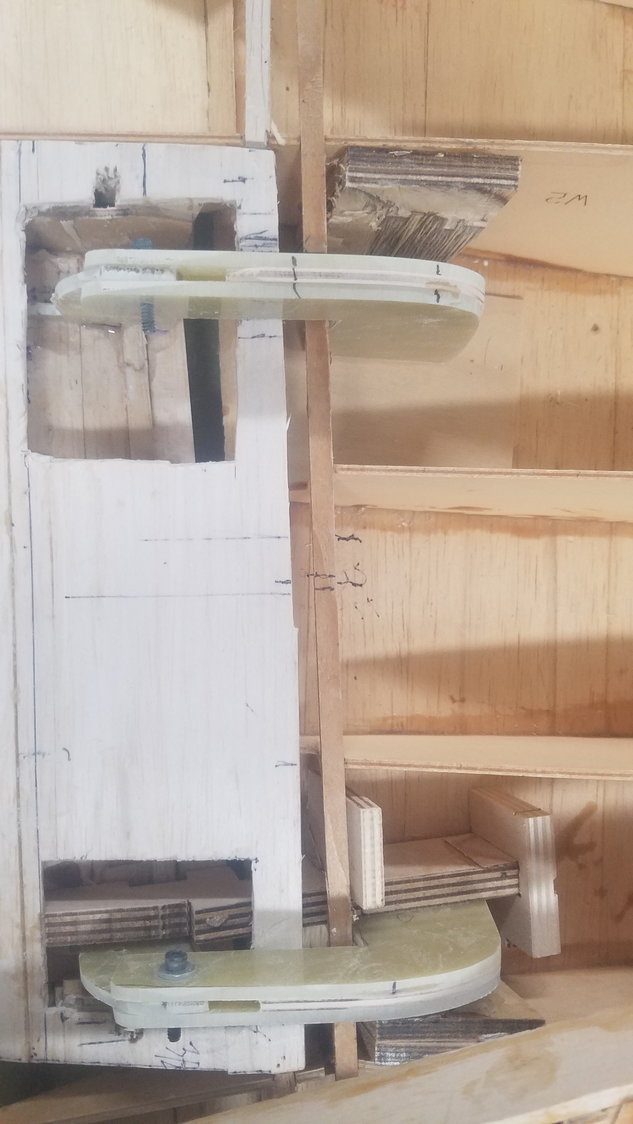
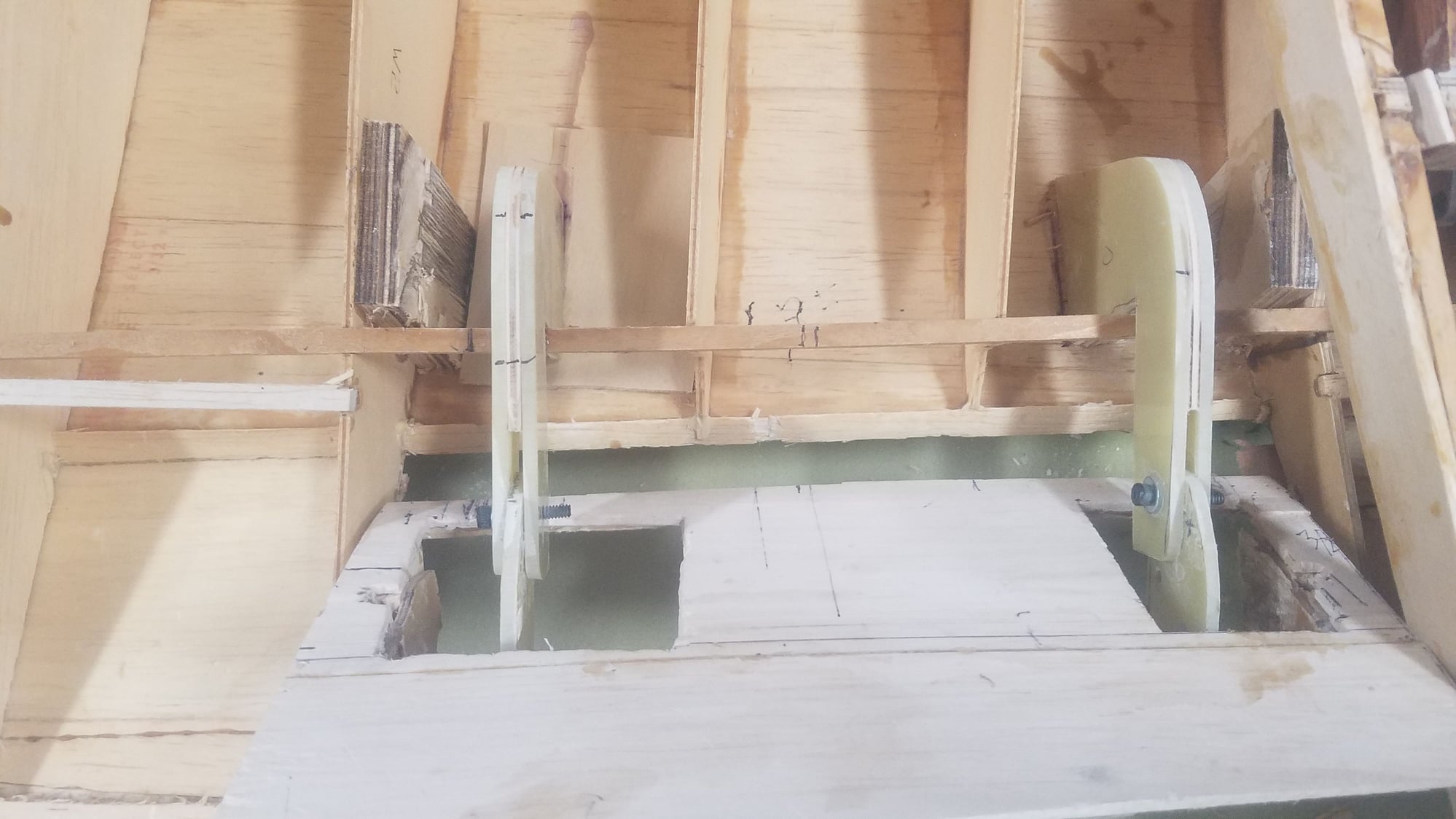
Vertical view of my jig. It is exact to the same size of the actual hinge in the wing. Some more work will be needed to get a placement for the hinge in the flap. It should be the exact center of the gig. I'll see if I can find center and make it usable to make the location for placement of the hinge.
Side view of the jig. This jig is as close as I can get to 90 degrees to flap face and plumb to the skin.
Jig is place showing the proper location and alignment of the hinges
Just another view of jig pulled back. More work to make it work in both left and right hinge locations in the flap.
As Sam showed, I went ahead and temporarily glued in the flaps. Also shows how I butchered up the flaps and how much work it will be to get the back in shape.
Vertical view of my jig. It is exact to the same size of the actual hinge in the wing. Some more work will be needed to get a placement for the hinge in the flap. It should be the exact center of the gig. I'll see if I can find center and make it usable to make the location for placement of the hinge.
Side view of the jig. This jig is as close as I can get to 90 degrees to flap face and plumb to the skin.
Jig is place showing the proper location and alignment of the hinges
Just another view of jig pulled back. More work to make it work in both left and right hinge locations in the flap.
07-22-2022, 05:28 PM
#107
Senior Member
Thread Starter
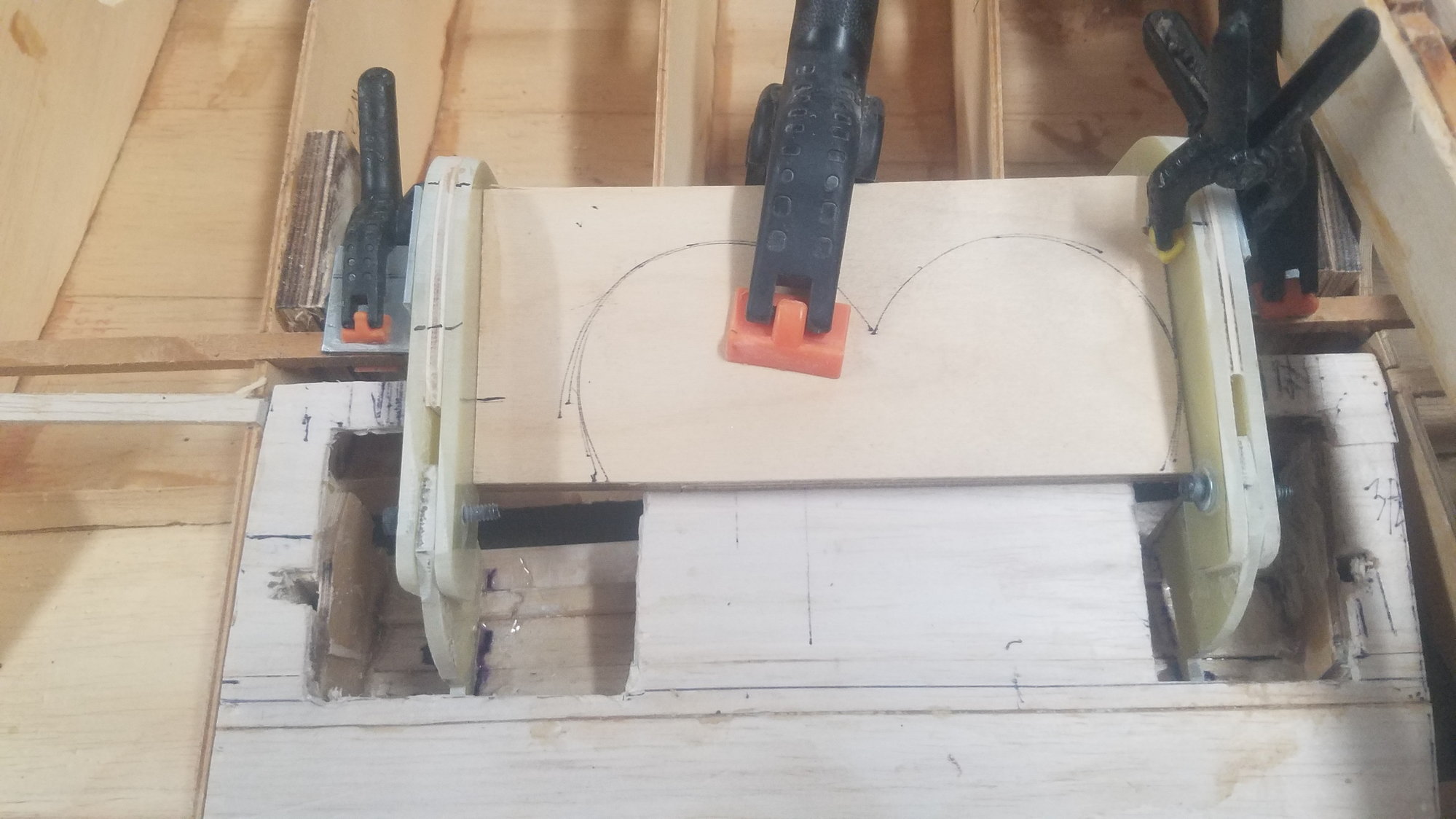
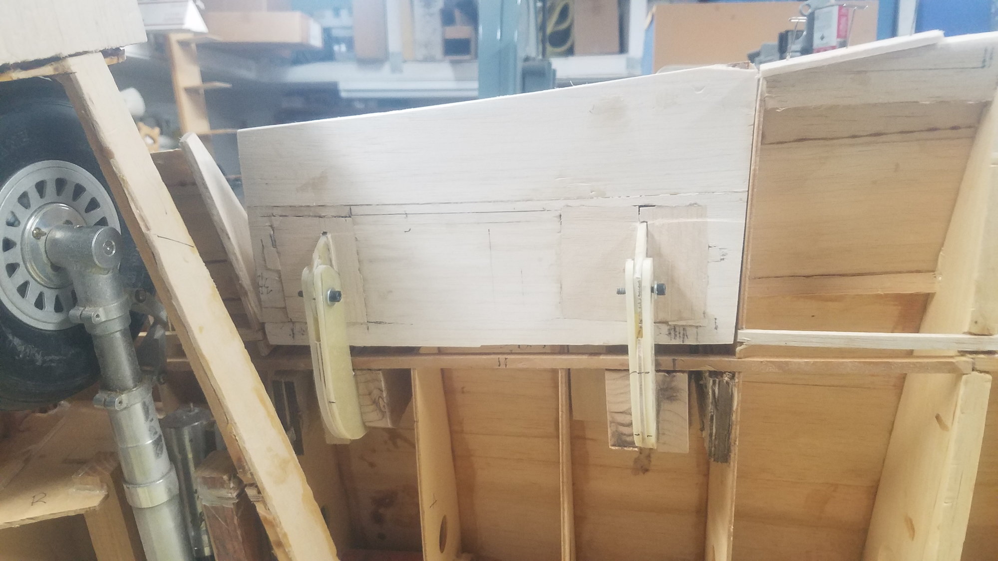
Made some adjustments in the jig design so it could be used in the different hinge locations. Also recut new hinges so they set flat on the skin of the wing and the flap This allows that they can be tacked in position for a test before the side reinforcements can be epoxied in place.
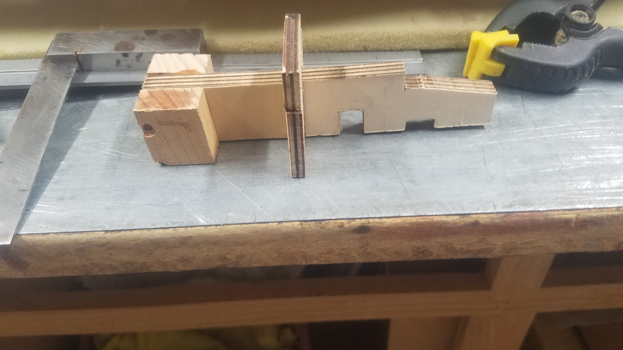
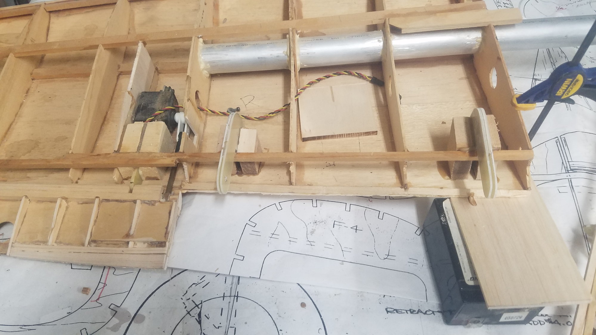
These are the newly cut hinges that reach the skin in both the wing and the flap. Each one is custom fit to its location on the left or right side of the flap.
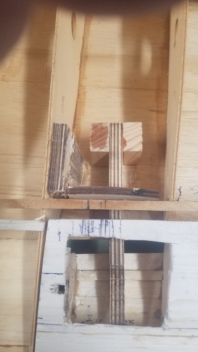
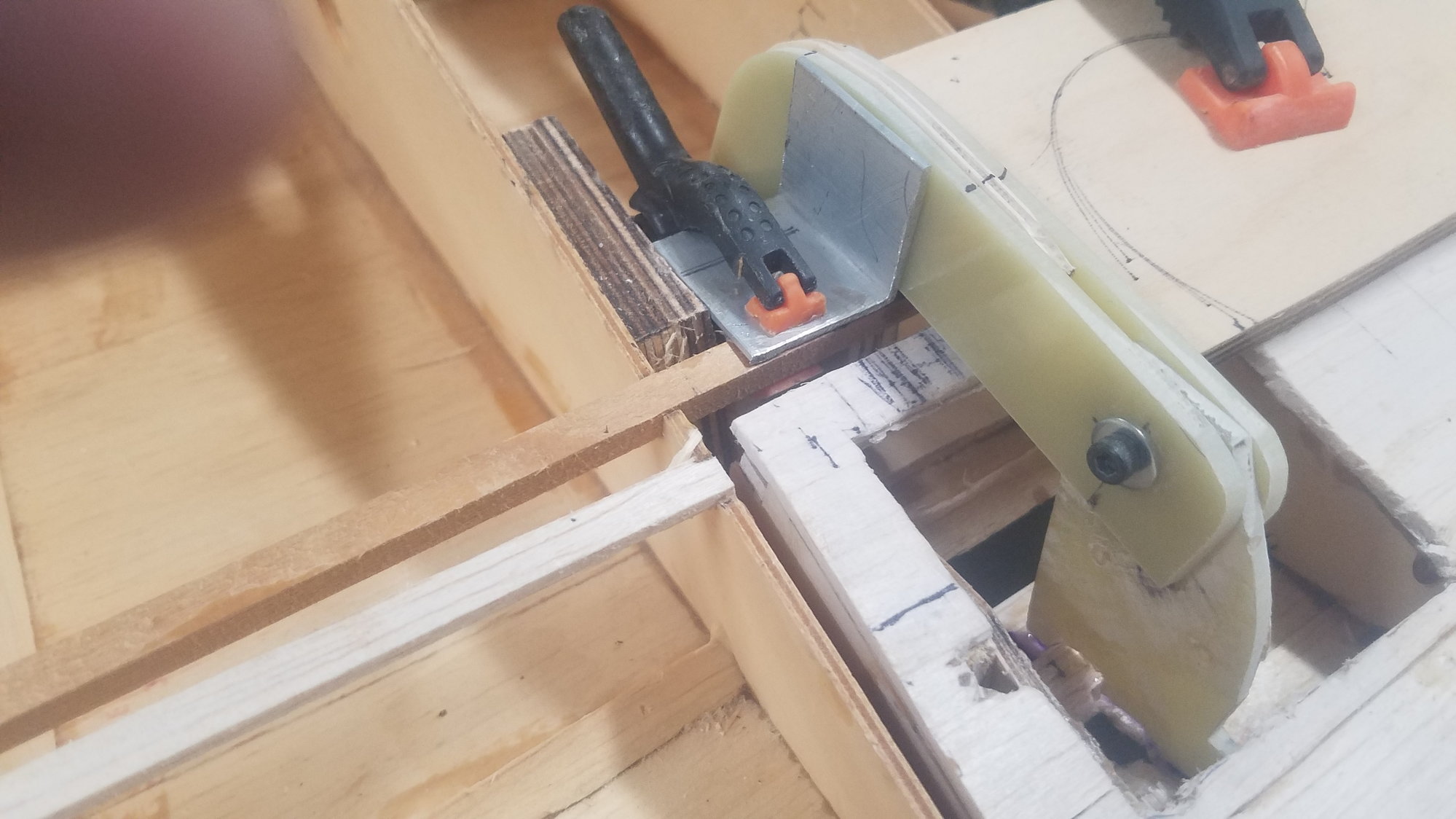
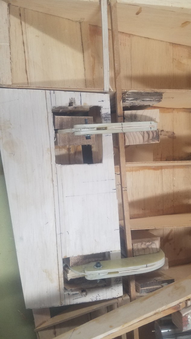
Jig in place. The crossbar at the rear sets the plum, perpendicular to the skin, and the side locator is removable so it can switch sides for left and right flap locations.
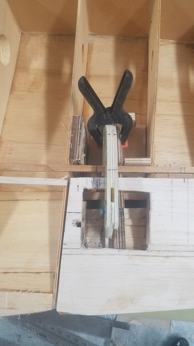
The side locator is set against the spar to set the correct angle to the flap. Here the hinge is clamped in place to the jig.
A rear view of hinge clamped in place. I used CA to temporarily set the hinge. Side supports will be epoxied in.
Left hinge glued in with CA and right side just setting up against the jig. I will measure across the hinges to ensure that they are parallel to one another.
.
.
These are the newly cut hinges that reach the skin in both the wing and the flap. Each one is custom fit to its location on the left or right side of the flap.
Jig in place. The crossbar at the rear sets the plum, perpendicular to the skin, and the side locator is removable so it can switch sides for left and right flap locations.
The side locator is set against the spar to set the correct angle to the flap. Here the hinge is clamped in place to the jig.
A rear view of hinge clamped in place. I used CA to temporarily set the hinge. Side supports will be epoxied in.
Left hinge glued in with CA and right side just setting up against the jig. I will measure across the hinges to ensure that they are parallel to one another.
.
.
Last edited by rossmick; 07-23-2022 at 06:17 AM.
07-23-2022, 05:48 PM
#108
Senior Member
Thread Starter
The jig idea worked pretty good but not good enough. I did not get a good alignment between the two hinges so went to plan E, or whatever came next. Just keep trying until you get it to work and yes, I finally got a good alignment, and the hinges do the fowler movement. Now on to the outboard flaps on the wings. Something went amiss and I could not type in text. Photos show flap deployed to 45 degrees and various shots of side reinforcements installed.
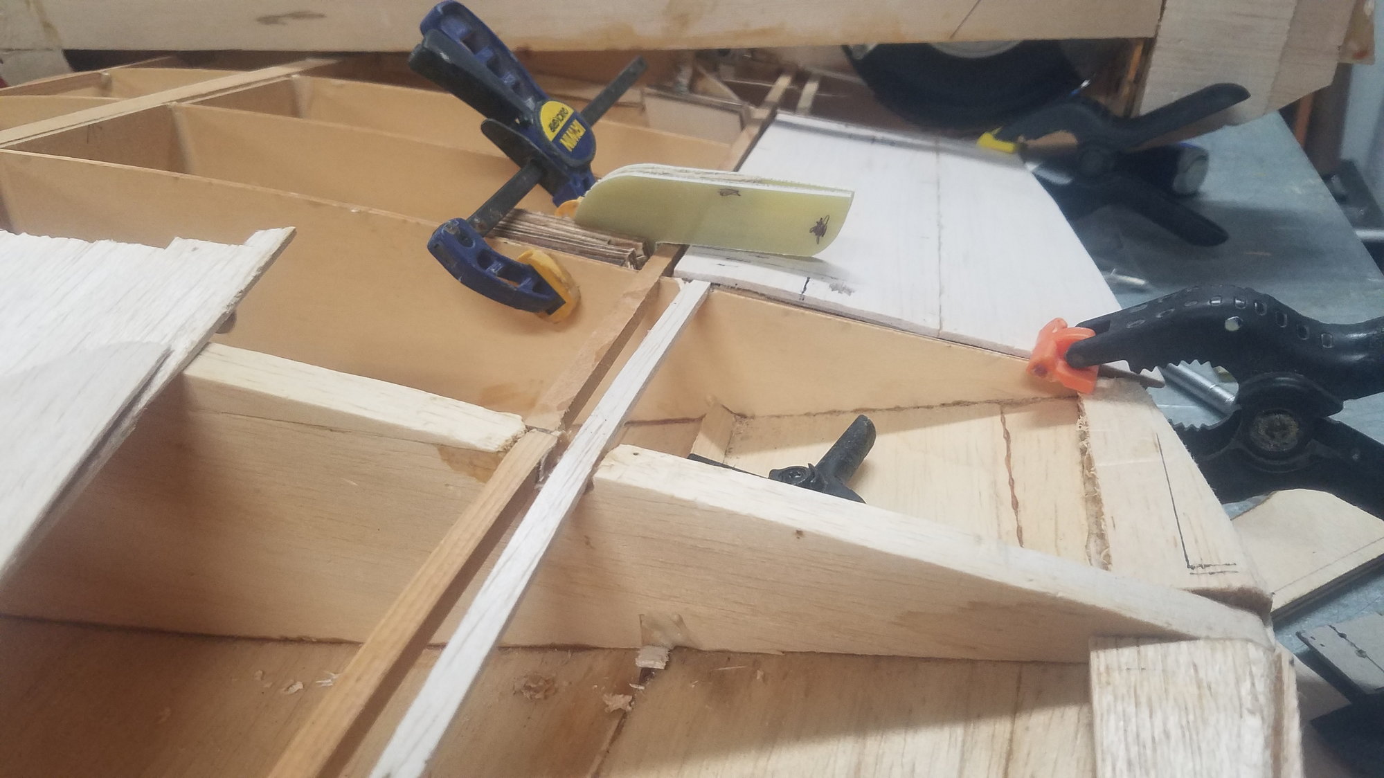
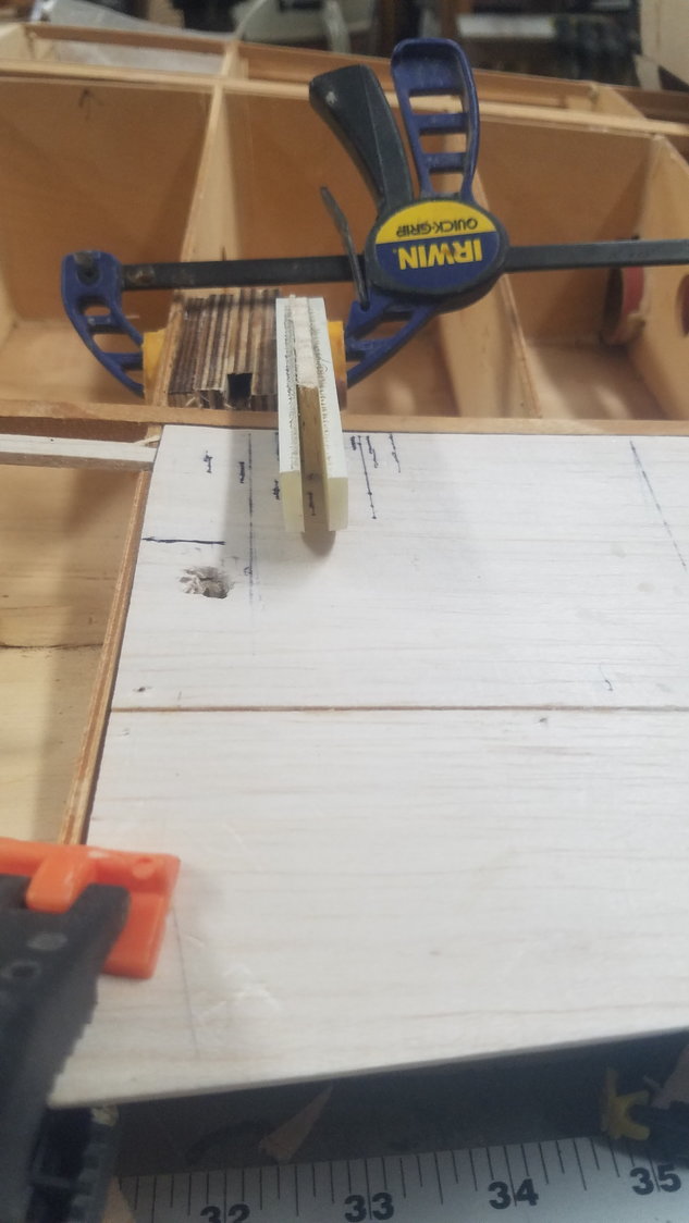
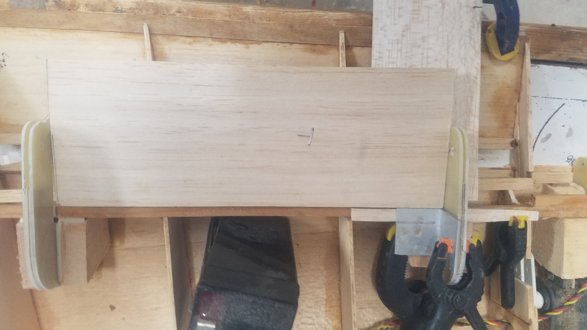
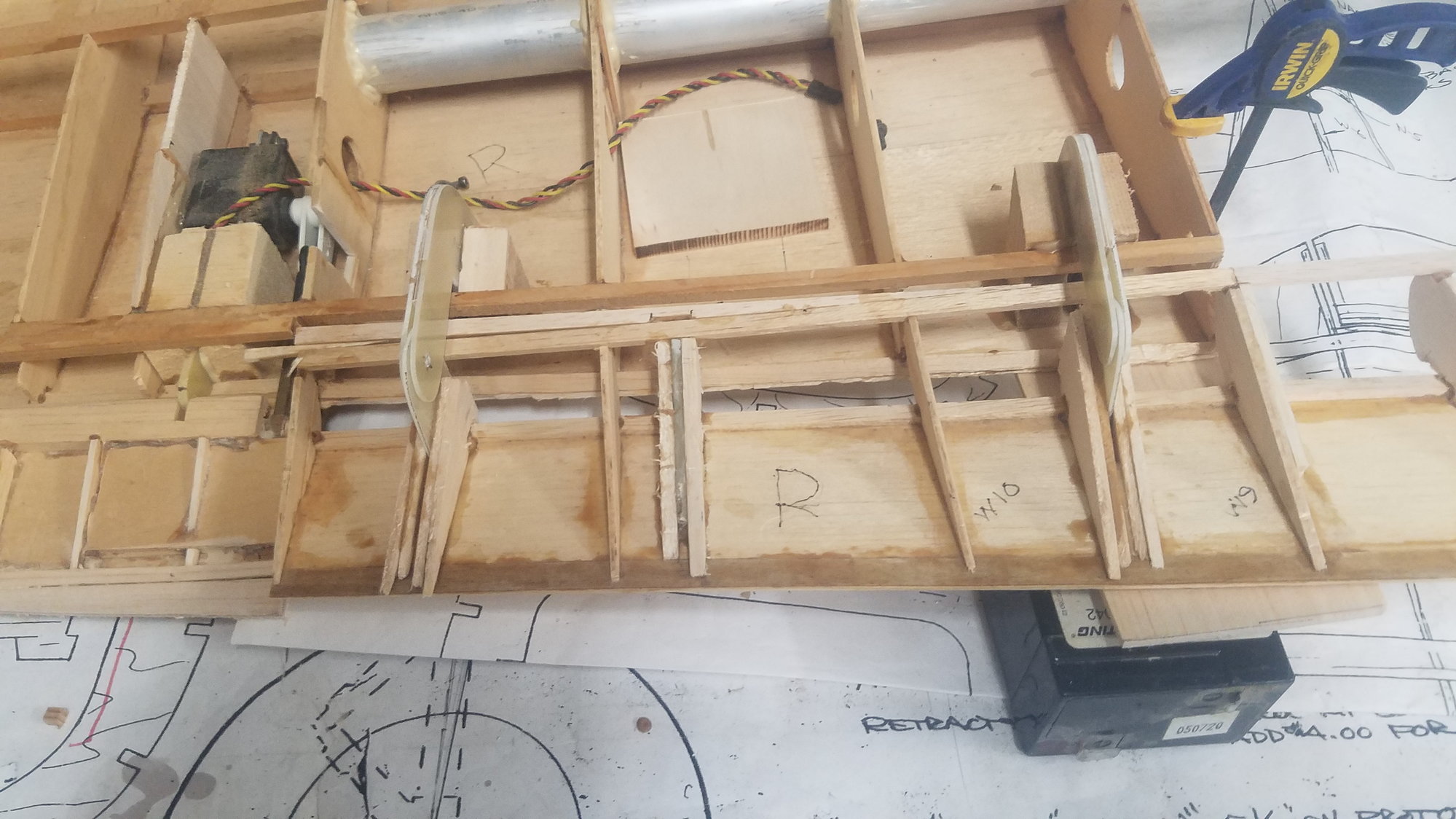
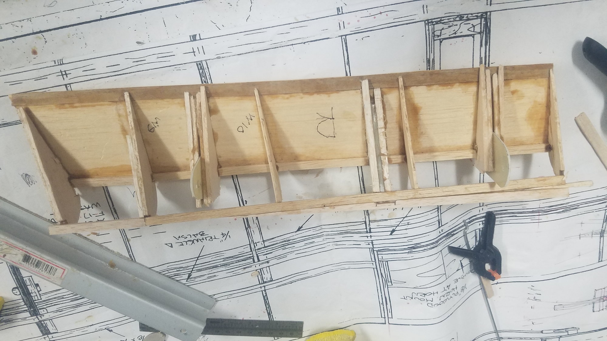
Here is the final setup. Two small squares (1x1 angle) on each side clamped to the spar and a perfectly squared jig to make the other hinge parallel. I first set one hinge perpendicular to the spar with a larger square and then set the parallel board and clamp it in.
Better photo of small square. A 1-inch angle is actually square. CA used to temporarily hold the hinges for a test. Cut the flap loose and it all works with no binding.
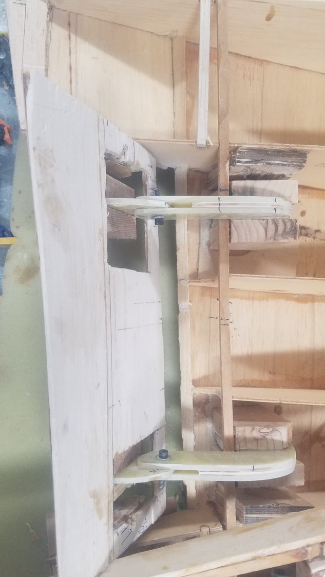
Last edited by rossmick; 07-23-2022 at 05:54 PM. Reason: Something went wrong and could not type in text.
07-25-2022, 07:30 PM
#109
Senior Member
Thread Starter
Patch day. Fixing the damage done with the tear out of first hinge install. Also close up area around hinge in the flap and other cracked or weak areas in the wing.
Patches on left flap top side. Learned a lesson to use one drop of CA for temporary attachments. I used too much and had to sand them off and or repair the skin that got pulled away.
Repair of trailing edge of wing including triangle edge for right flap. Patched hole in wing and split and cracked area
Areas closed in around the hinge on left flap.
Will close up the right flap tomorrow and glue in the servo attach point in both flaps. The attach point has to be redesigned due to fowler flap setup and will take some time to figure out. Would like to get servos mounted and linkage installed to test the flap operation.
Last edited by rossmick; 07-25-2022 at 07:36 PM.
07-26-2022, 08:55 PM
#110
Senior Member
Thread Starter
Servo attach point designed. New JR RG812BX and RG812BX-B receivers to get 16 channels. Want to see how the servo will drive the flap and where to install it.
Attach point laid out to miss the trailing edge of the wing.
Flap retracted position
Flap deployed to 45 degrees. Looks pretty good, will find out when servo is installed. Looks like it will take a longer servo arm to get full deployment.
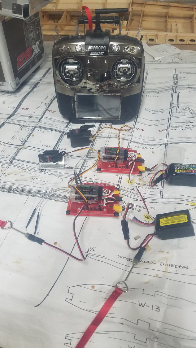
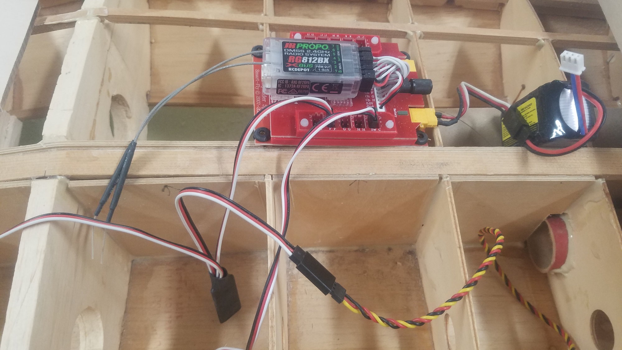
Radio setup. JR 28X and new RG812BX receivers with the Smart-Fly boards. These boards provide the power and isolation to the servos. This model also has the ignition switch for the motors. Also, supplies automatic 5-volt power switch over if one battery goes low. The reason I really like the Smart-Fly board is that if a servo shorts the board just shuts down that channel and the receiver is isolated and continues to operate.
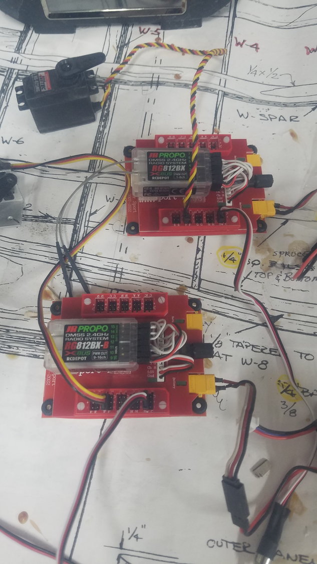
These two receivers allow for 16 PWM channels, could also go to the X-Bus system if I wanted. Tested channels 9-16 and all worked as advertised.
Attach point laid out to miss the trailing edge of the wing.
Flap retracted position
Flap deployed to 45 degrees. Looks pretty good, will find out when servo is installed. Looks like it will take a longer servo arm to get full deployment.
Radio setup. JR 28X and new RG812BX receivers with the Smart-Fly boards. These boards provide the power and isolation to the servos. This model also has the ignition switch for the motors. Also, supplies automatic 5-volt power switch over if one battery goes low. The reason I really like the Smart-Fly board is that if a servo shorts the board just shuts down that channel and the receiver is isolated and continues to operate.
These two receivers allow for 16 PWM channels, could also go to the X-Bus system if I wanted. Tested channels 9-16 and all worked as advertised.
07-27-2022, 06:19 PM
#111
Senior Member
Thread Starter
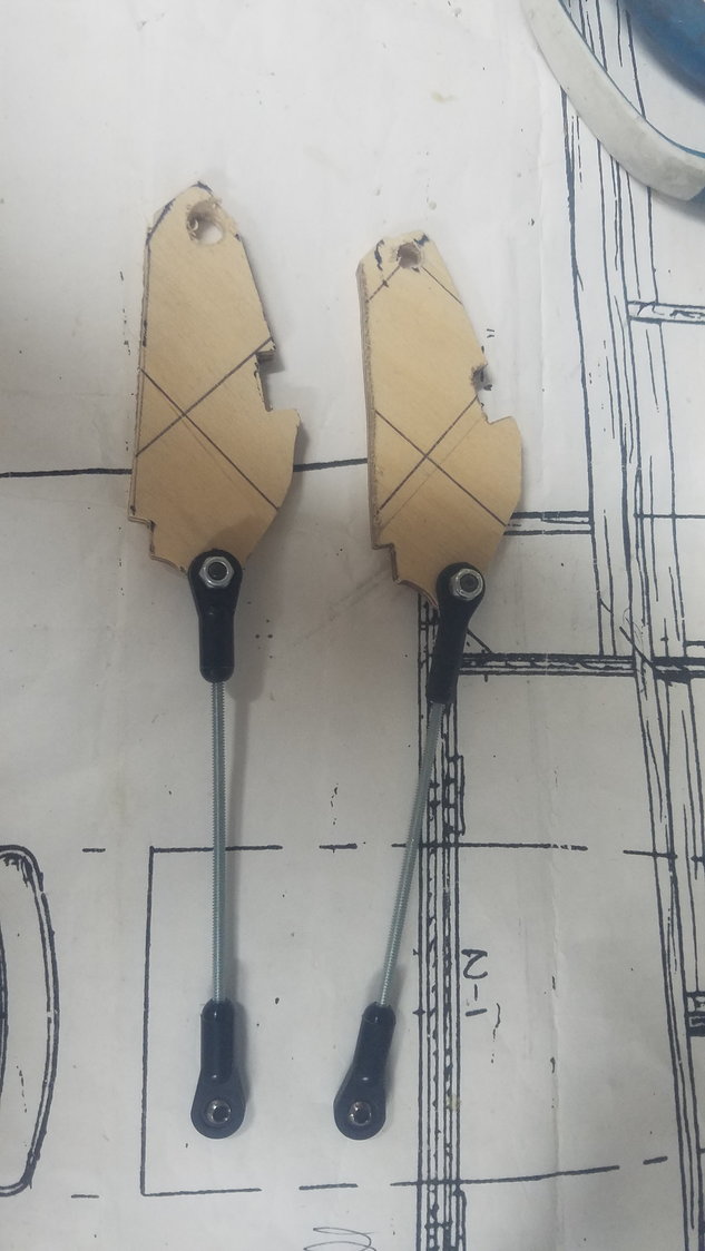
3/8-inch ply servo attach point designed and 4-40 push rod with swivel ball links installed.
Attach point installed in flaps. Will seal up flaps tomorrow and install the servos.
07-28-2022, 08:46 PM
#112
Senior Member
Thread Starter
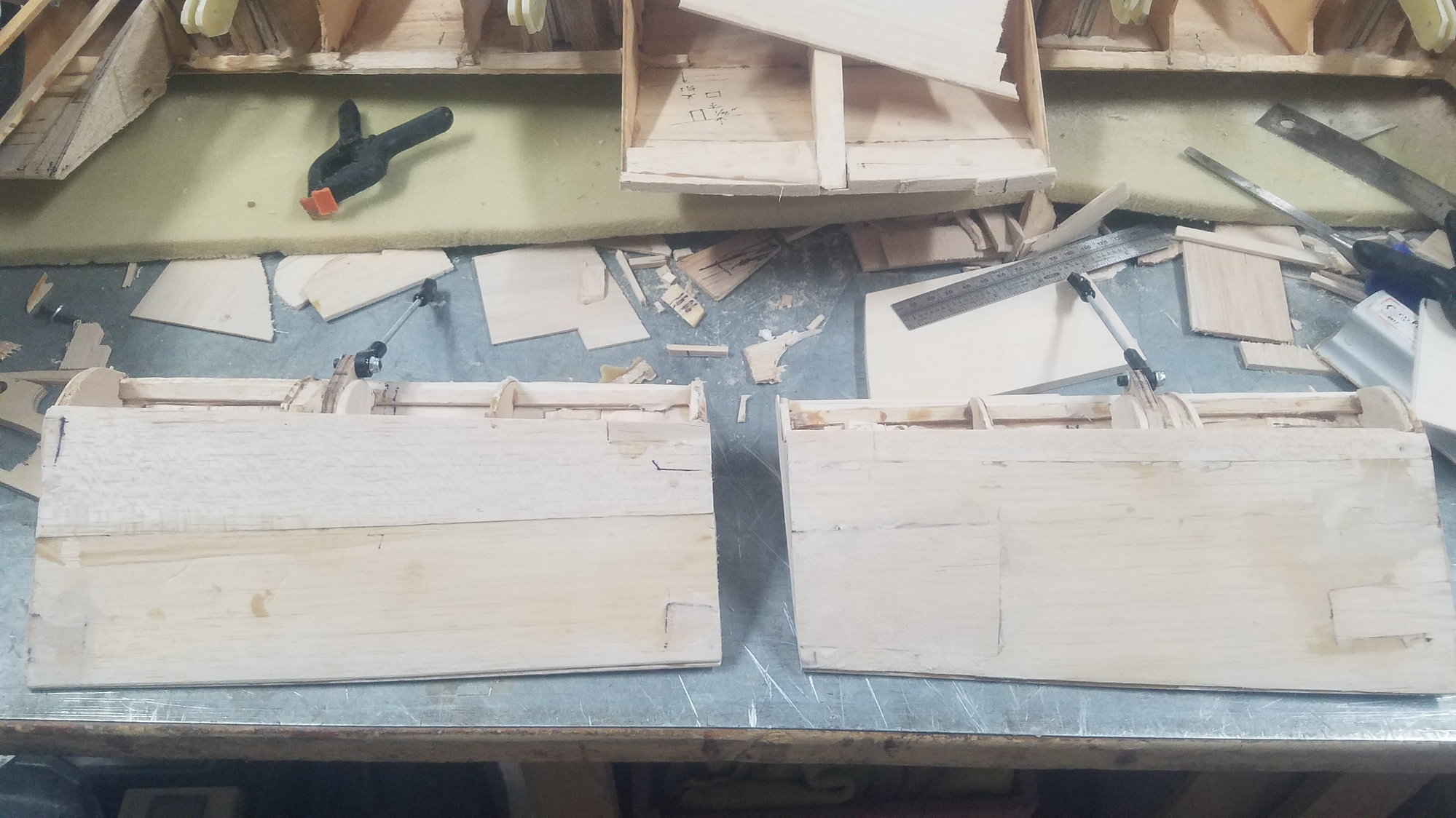
I did not have much time today, but got flaps enclosed and servo mounts cut.
Left flap enclosed and will sand edges tomorrow.
Same goes for the right flap. For a while, I thought I'd never get here. It has taken weeks to get this flap scheme setup.
Cut servo mounts from Aluminum angle. Will change screw down holes from 2 to 4. Will install plywood base pad between ribs then screw down servo to it.
07-29-2022, 07:10 PM
#113
Senior Member
Thread Starter
Finished inboard flap installation, and boarders for access hatch installed. I am very glad to get past this install and now on to the outboard flap's configuration. Hopefully, will go much quicker from lessons learned here.
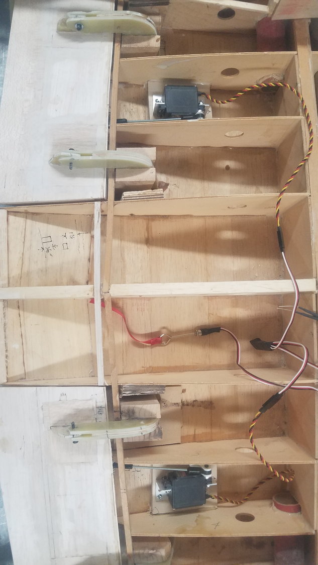
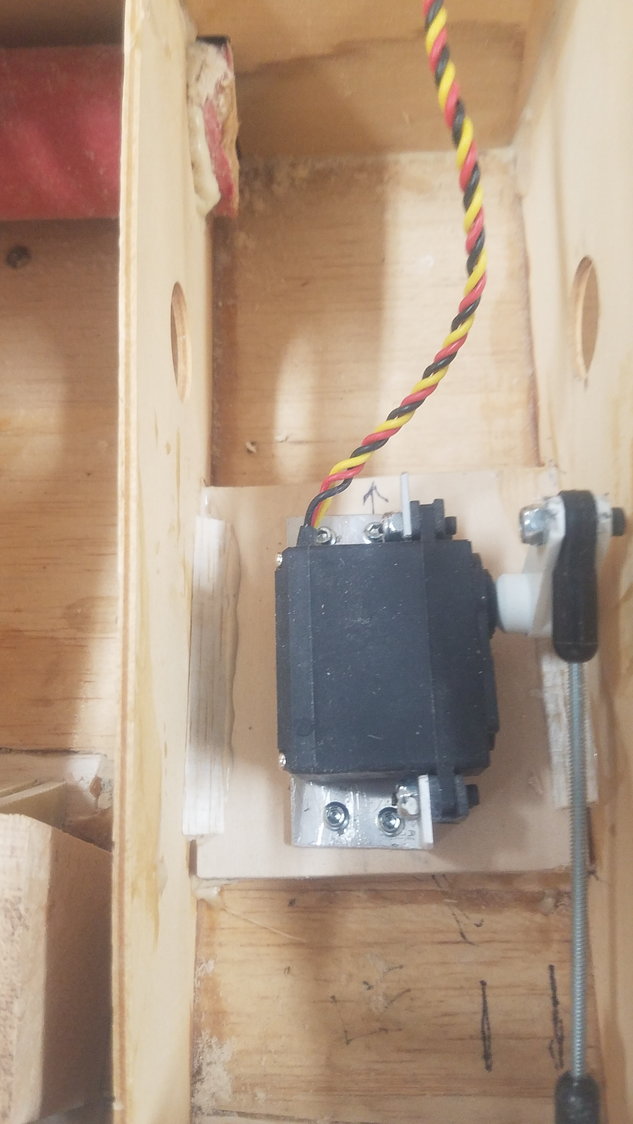
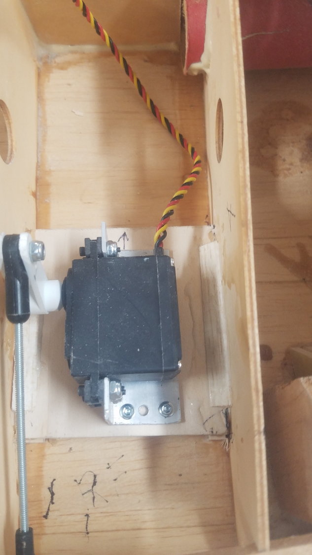
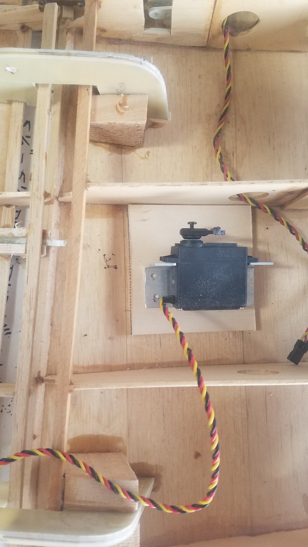
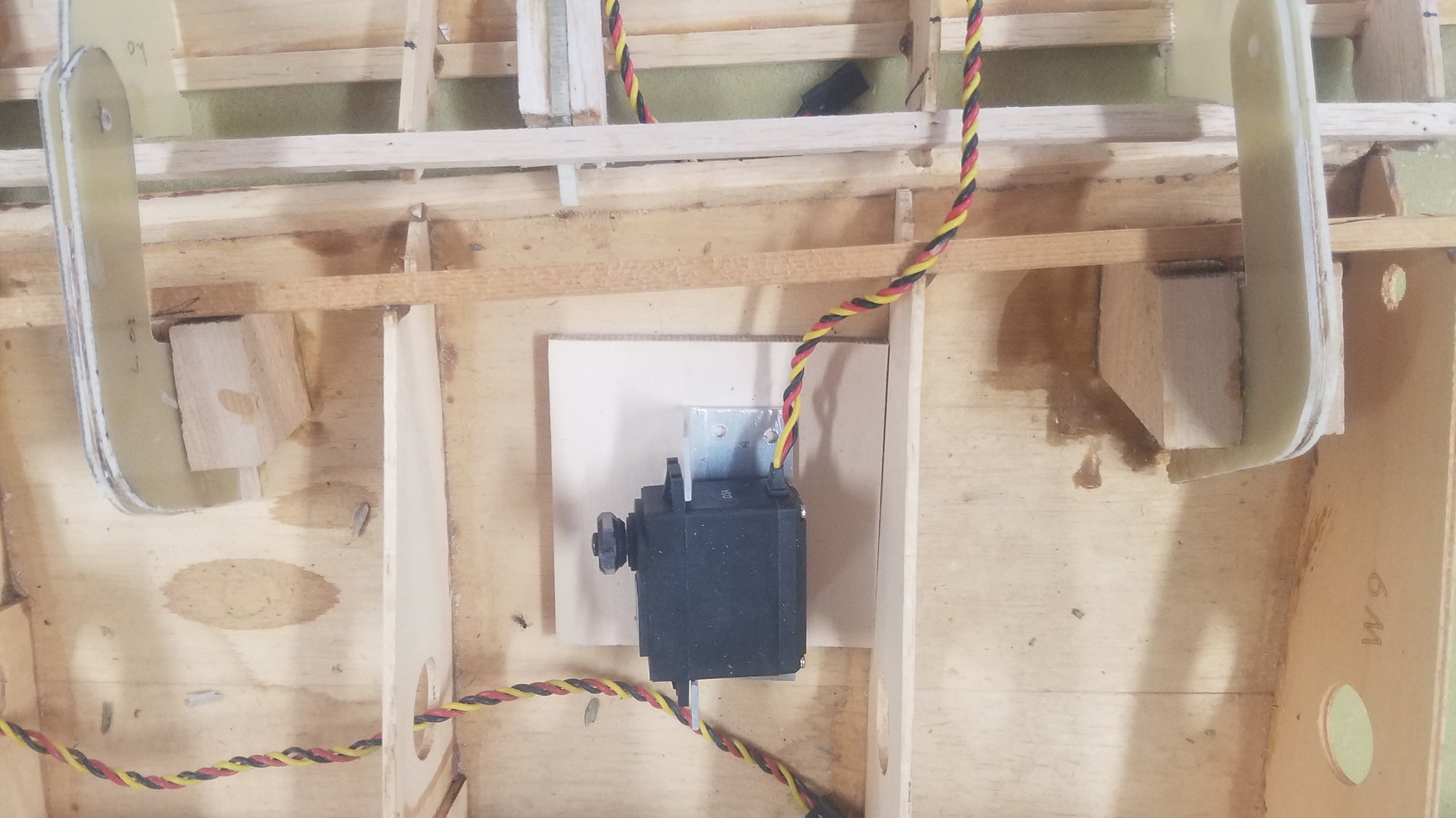
Servos installed on 1.4" basswood plate raised another 1/4" on spacers. All glued to the ribs and to the top skin
Had to use a reverser off the Y cable to get the right-hand servo to move in the correct direction.
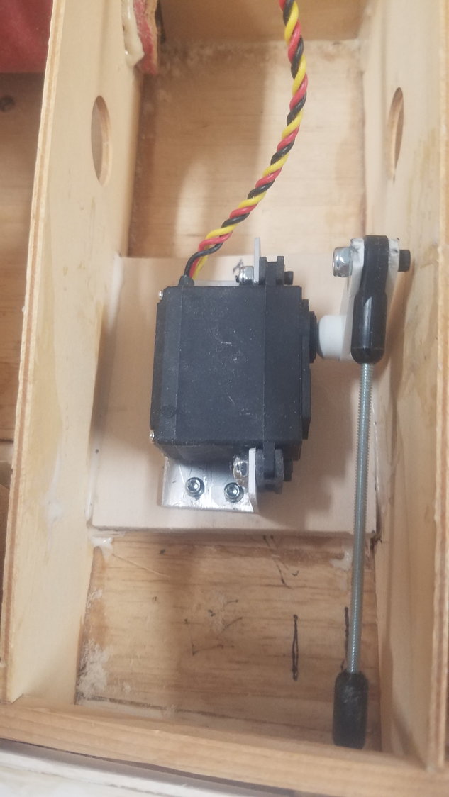
Right Servo attached to glued in plate. Used dual servo arm for more stability using middle hole for proper flap deflection.
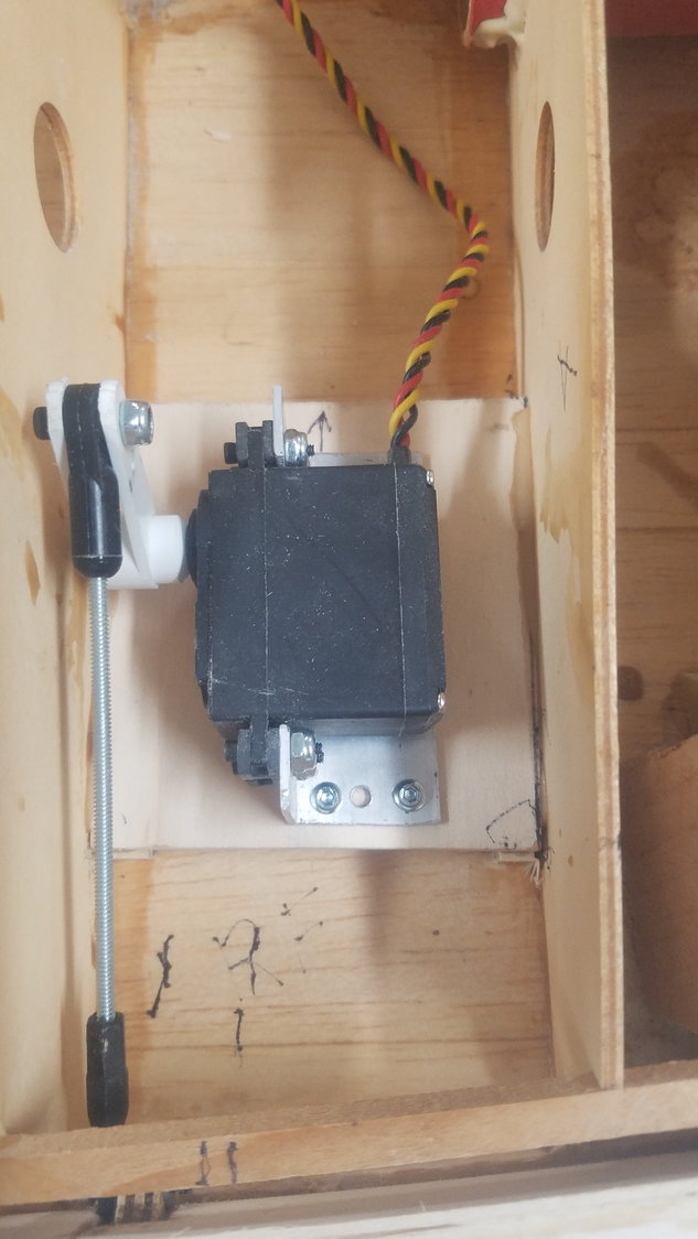
Left servo attached to glued in plate. Dual servo arm was reduced to use the middle hole for proper flap deflection.
Test of operation was successful. Will need to spend some more time setting up the transmitter to get a small deflection at mid switch.
Added gussets to the ribs from the plate
Gussets installed on the left as well.
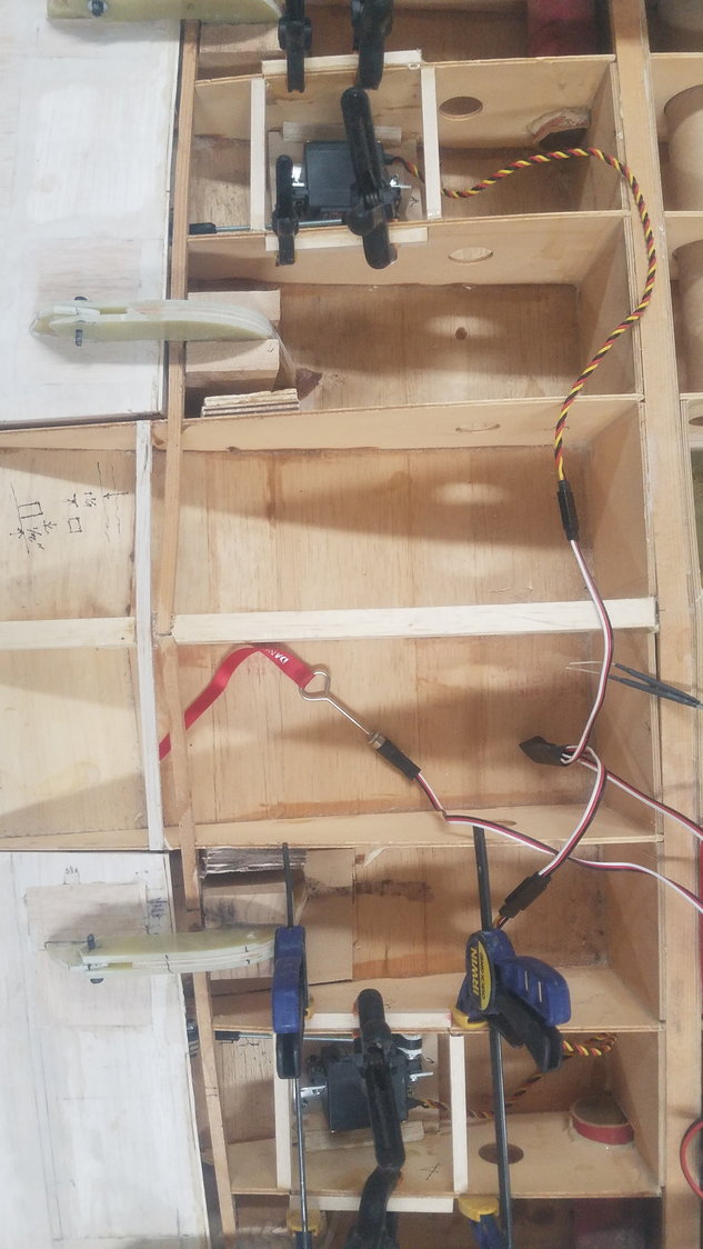
Hard wood hatch attachments glued in.
Servos installed on 1.4" basswood plate raised another 1/4" on spacers. All glued to the ribs and to the top skin
Had to use a reverser off the Y cable to get the right-hand servo to move in the correct direction.
Right Servo attached to glued in plate. Used dual servo arm for more stability using middle hole for proper flap deflection.
Left servo attached to glued in plate. Dual servo arm was reduced to use the middle hole for proper flap deflection.
Test of operation was successful. Will need to spend some more time setting up the transmitter to get a small deflection at mid switch.
Added gussets to the ribs from the plate
Gussets installed on the left as well.
Hard wood hatch attachments glued in.
07-30-2022, 07:33 PM
#114
Senior Member
Thread Starter
Today was clean and reorganize the shop. Things get pretty scattered as you work and then you spend more time just trying to find things.
Now on to the outboard wing flaps. I had considered trying to use the brass and Robart hinge idea but have decided to just use 1/16" G-10 that I had just ordered.
Laying out the same concept as I used on the inboard flap. This will use 1/16" G-10 and the overall size is smaller.
Laid out design for G-10 cut for outboard flap off the plan.
Pieces all cut out including the 1/16" ply. spacer.
Flap in position
07-31-2022, 07:53 PM
#115
Senior Member
Thread Starter
Continued work on outboard wing flaps.
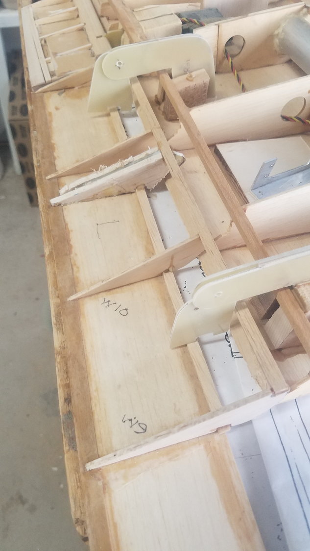
Installing hinges on left wing. This time more attention given to correct height above the flap.
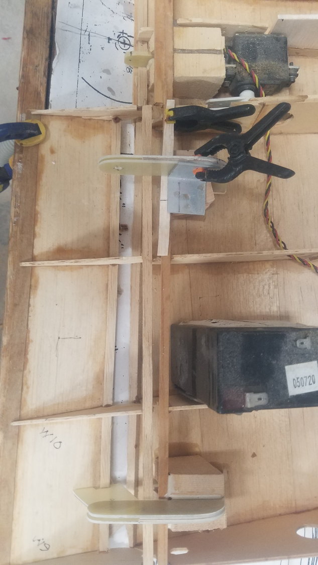
Hinges on right wing, again using the small angle to ensure hinge is square with the wing.
Use of jig to ensure hinges are parallel.
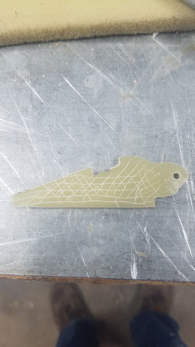
Like all G-10 parts they are heavily scored before being glued in.
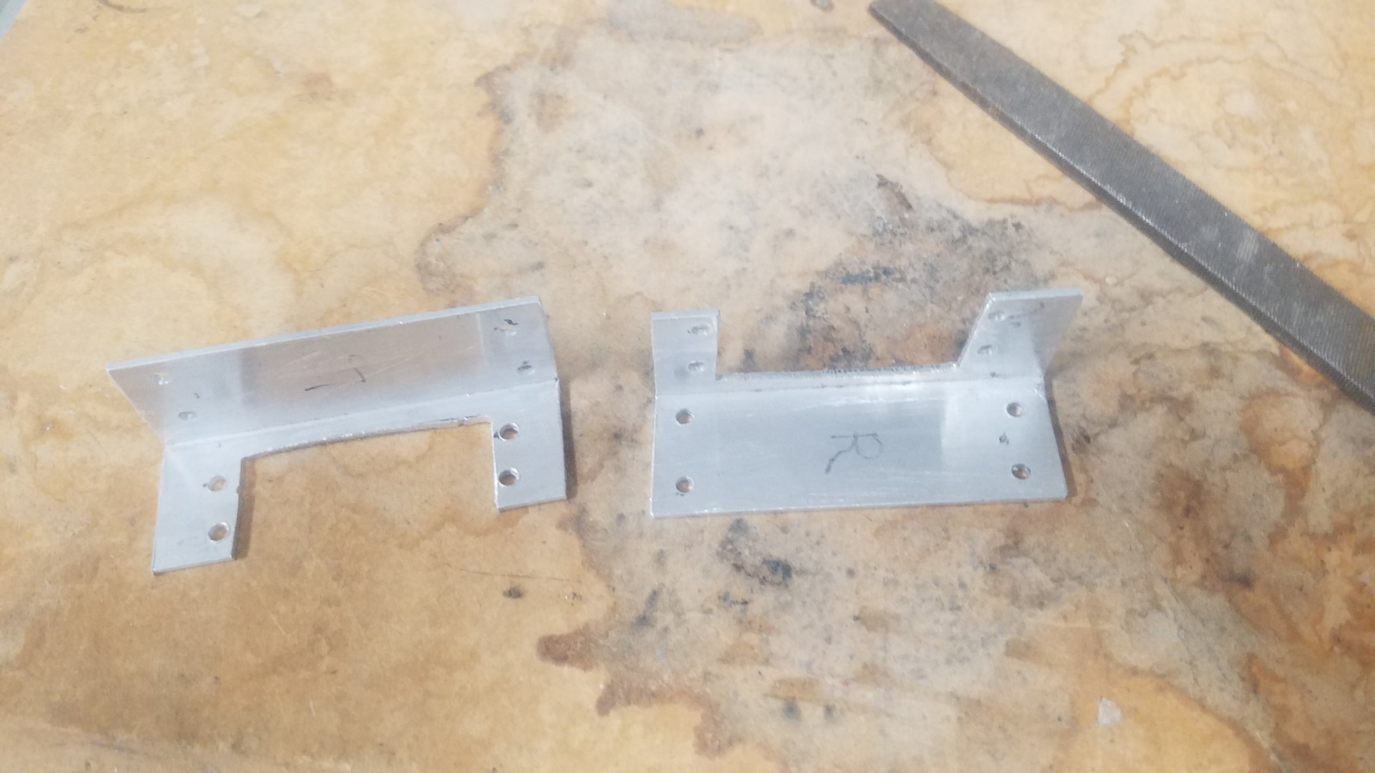
Servo mounts cut and drilled. All edges are filed smooth, and holes have all the flashing filed off.
Servo attach point designed and installed on wing.
Servo attach point installed on left wing, notice different location than the opposite wing.
This time the servos are installed so that a reverser is not needed on the Y cable.
1/4" bass wood plate to be glued in to mount the servos after setting their position.
Installing hinges on left wing. This time more attention given to correct height above the flap.
Hinges on right wing, again using the small angle to ensure hinge is square with the wing.
Use of jig to ensure hinges are parallel.
Like all G-10 parts they are heavily scored before being glued in.
Servo mounts cut and drilled. All edges are filed smooth, and holes have all the flashing filed off.
Servo attach point designed and installed on wing.
Servo attach point installed on left wing, notice different location than the opposite wing.
This time the servos are installed so that a reverser is not needed on the Y cable.
1/4" bass wood plate to be glued in to mount the servos after setting their position.
08-01-2022, 07:23 PM
#116
Senior Member
Thread Starter
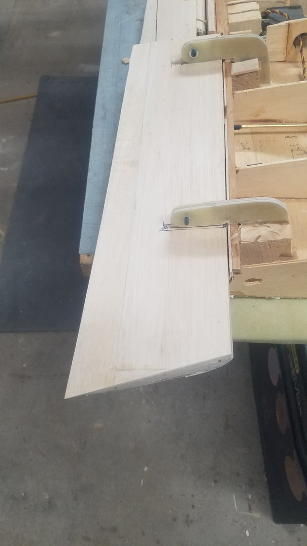
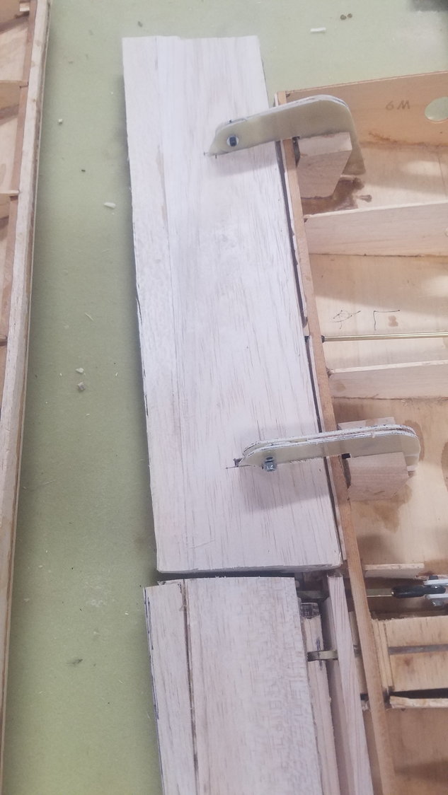
Not too much time for the B-25 today. Did get one outboard flap setup to the hinges.
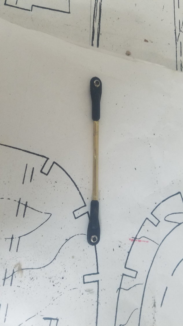
Flap aligned with the wing and held in position. Hinges connected to the flap. Servo 3mm pushrod assembled, but needs brass tube, or channel, to stiffen it before it can be installed
Flap aligned with the wing and held in position. Hinges connected to the flap. Servo 3mm pushrod assembled, but needs brass tube, or channel, to stiffen it before it can be installed
08-02-2022, 07:30 PM
#117
Senior Member
Thread Starter
Slowly moving ahead on the flaps. Another lesson learned for me is, you will spend a tremendous amount of time reworking and correcting a plane that has been put on the shelf for a matter of years that was partially built. Not only having to fix the damage to the loose parts that were laying around, but you find all the mistakes and poor building moves that you now know not to do. Long story short, if you are going to build, keep going until you finish. If you put it on the shelf, expect a much longer, and frustrating, time to continue the work on the plane.
Off to the hardware store to get the correct size brass tube to strengthen the 3mm threaded rod.
Repaired and corrected the flap, fixed ribs and stringers which were lost or damaged in storage. This has taken many more hours than if the flap had been built from scratch.
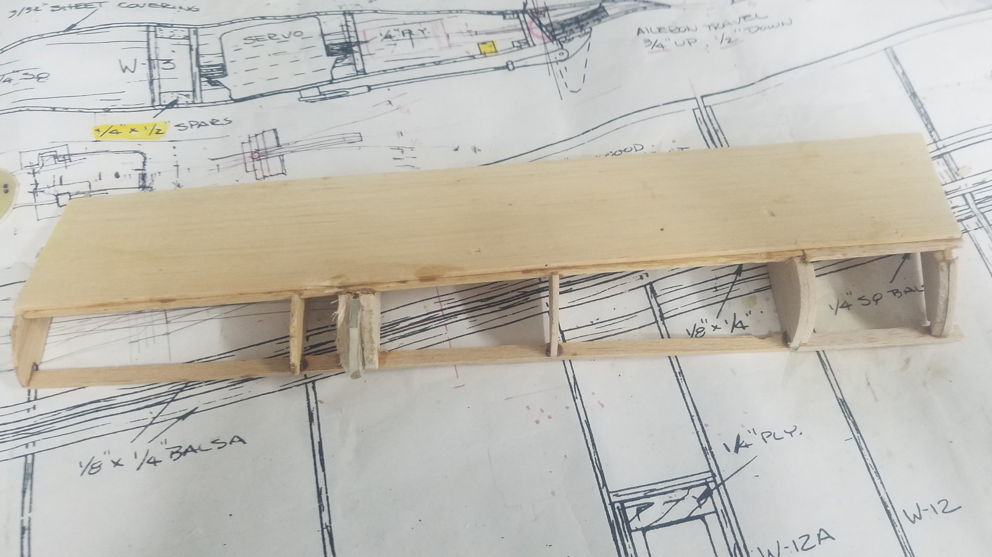
Begin skinning of the flap. The servo attach point had to be modified to miss the wing when the flap rotated to 45 degrees.
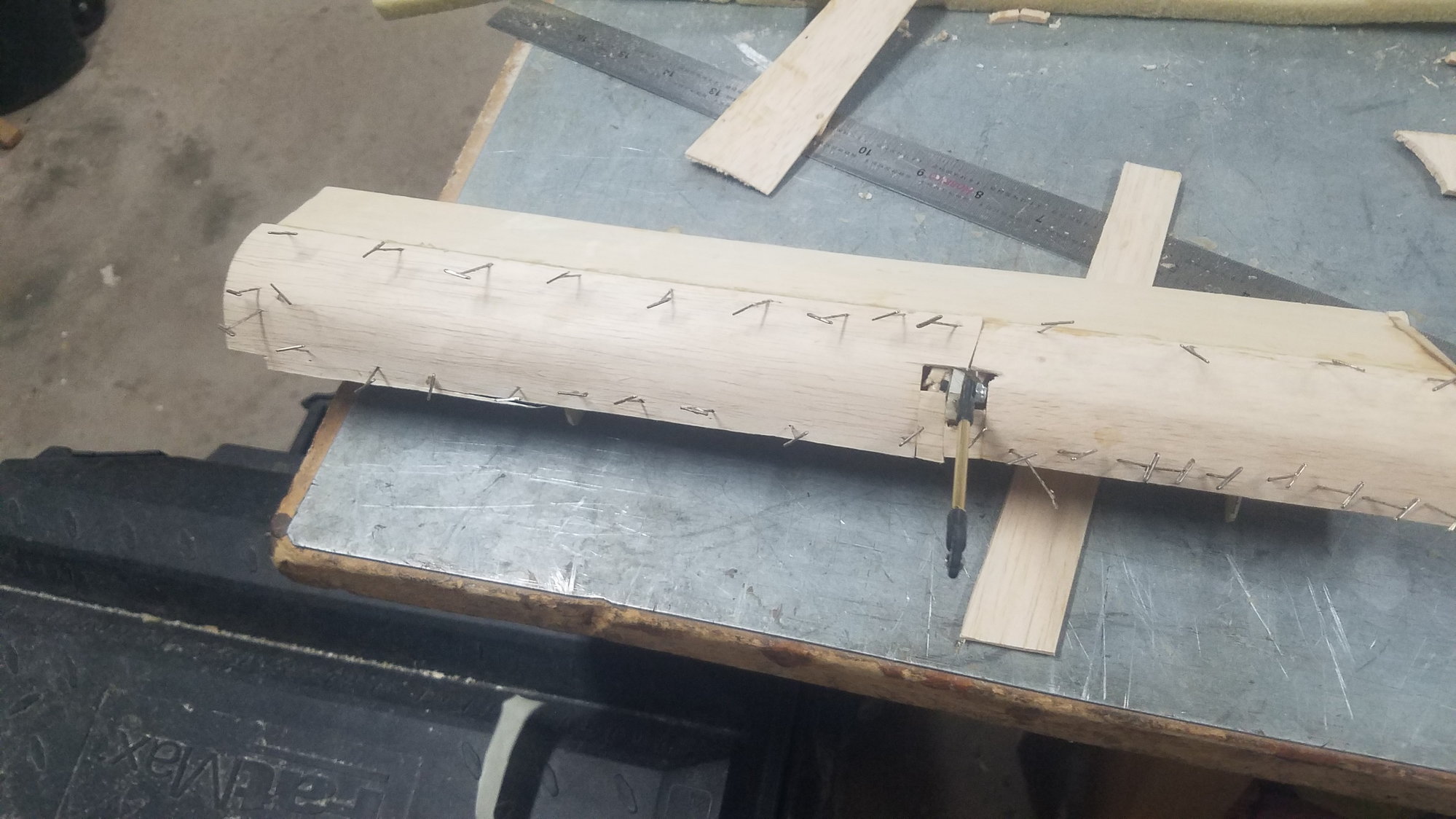
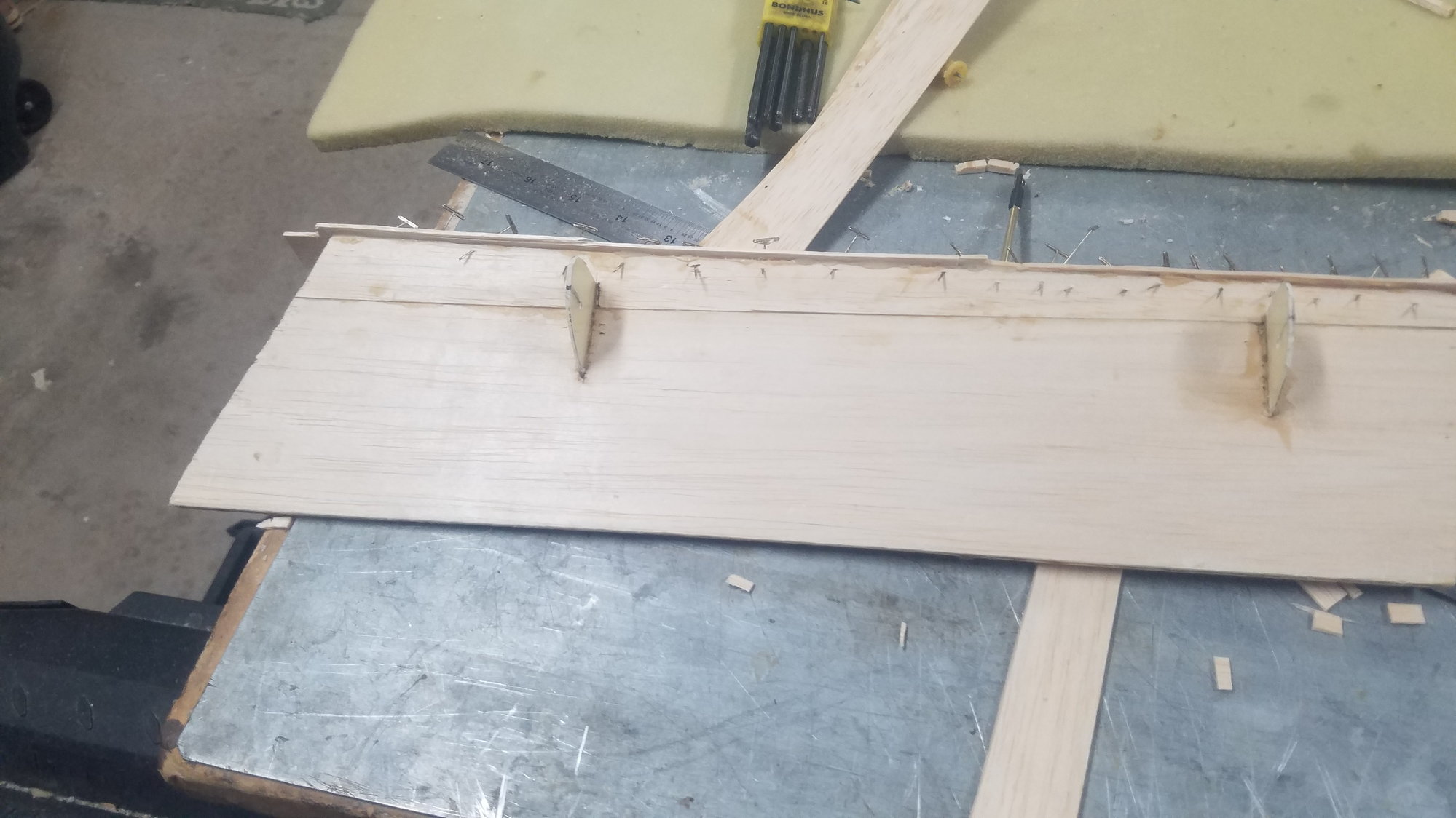
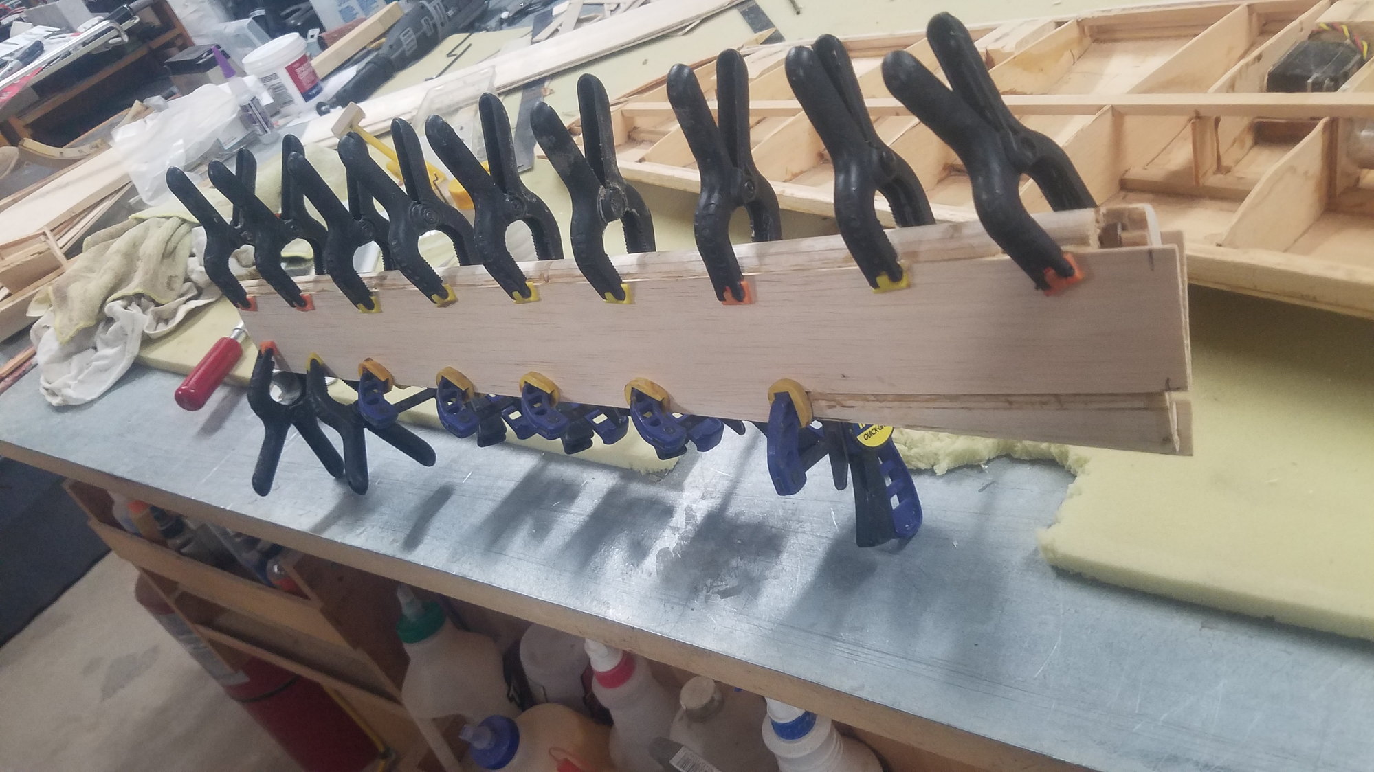
Closing up the flap with lots of pins. Push rod attached.
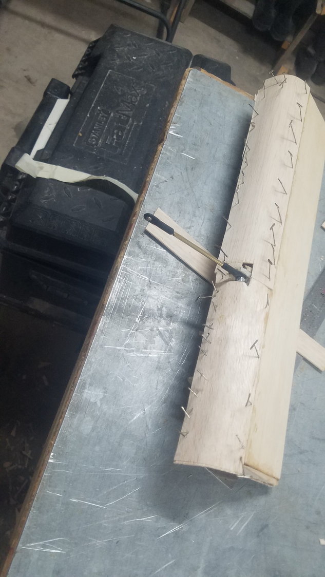
Another view of applying the skin and closing the flap.
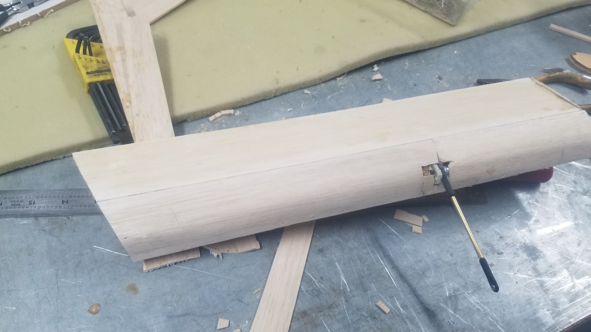
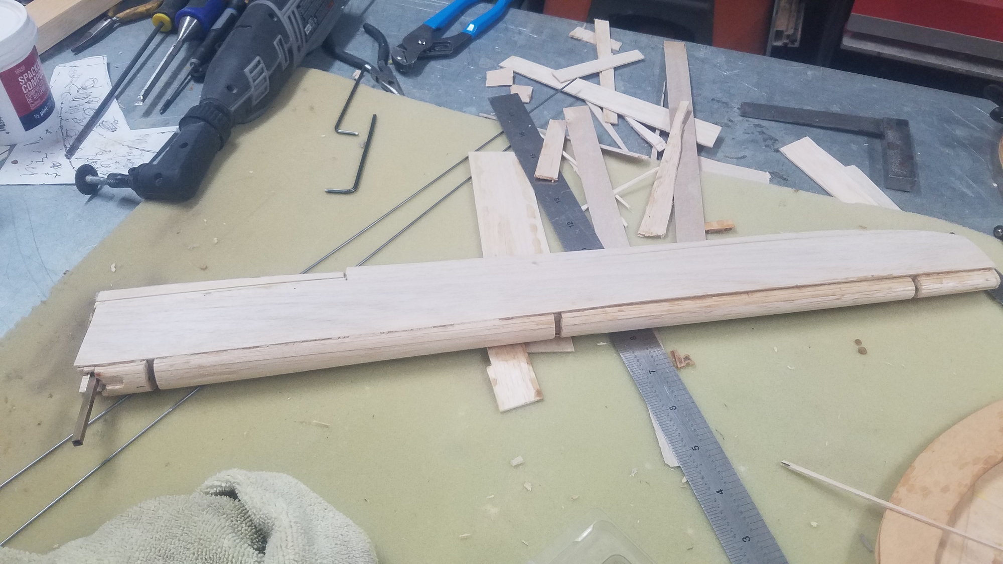
Pins removed and initial sanding and trimming done. Flaps have taken a tremendous amount of time and I still have one to go - tomorrow.
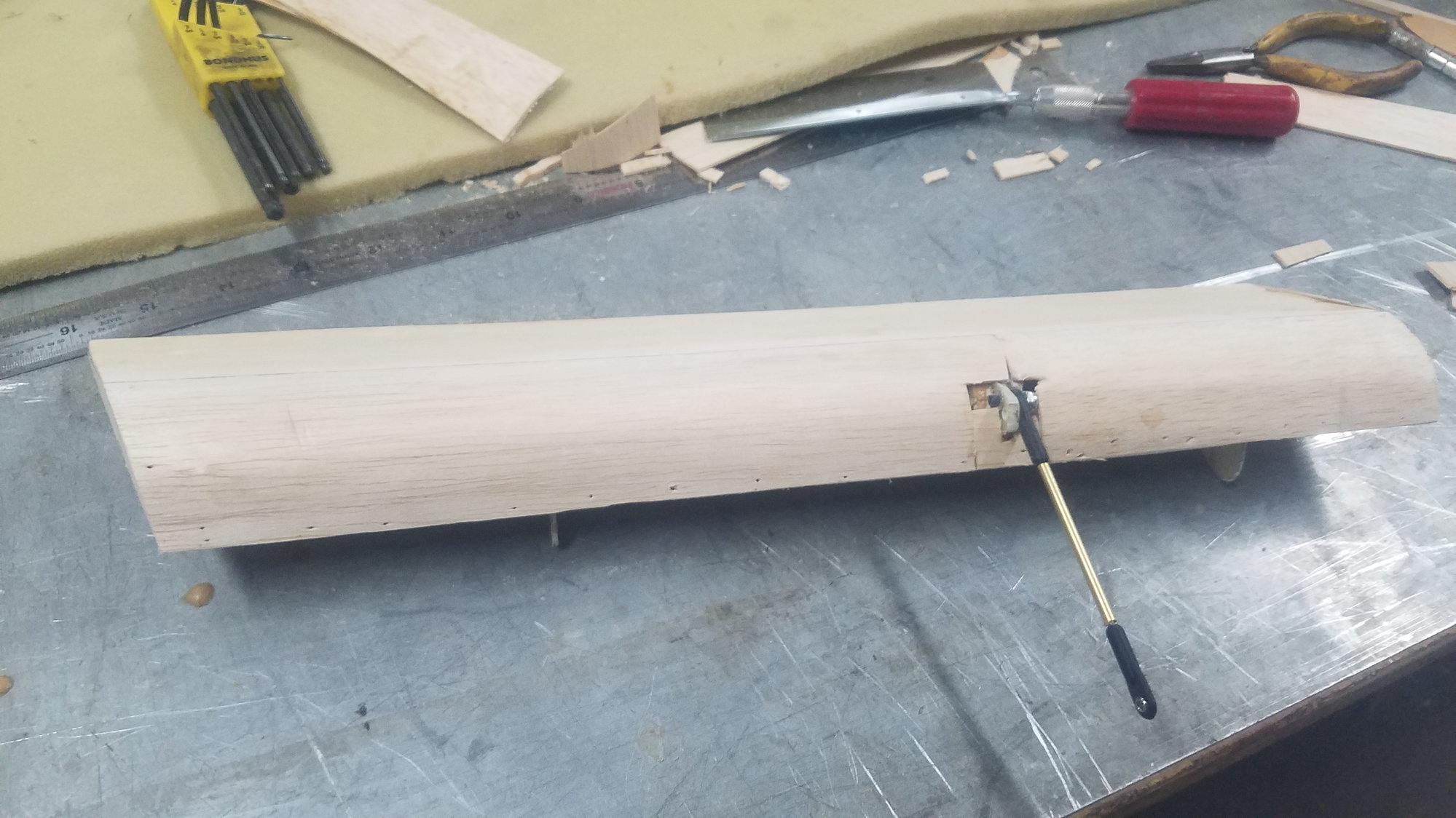
Better view of sanding on the skin. Will spend some time closing the area around the attach point and final filling of pin holes and sanding.
Off to the hardware store to get the correct size brass tube to strengthen the 3mm threaded rod.
Repaired and corrected the flap, fixed ribs and stringers which were lost or damaged in storage. This has taken many more hours than if the flap had been built from scratch.
Begin skinning of the flap. The servo attach point had to be modified to miss the wing when the flap rotated to 45 degrees.
Closing up the flap with lots of pins. Push rod attached.
Another view of applying the skin and closing the flap.
Pins removed and initial sanding and trimming done. Flaps have taken a tremendous amount of time and I still have one to go - tomorrow.
Better view of sanding on the skin. Will spend some time closing the area around the attach point and final filling of pin holes and sanding.
08-04-2022, 06:49 PM
#118
Senior Member
Thread Starter
Testing and setting servo position on left wing. Did require reverser Y cable to work correctly.
Repaired flap removed and will require more work.
Flap temporarily back in position for servo pushrod dimension and servo location.
Ribs to be reworked tomorrow and hopefully will be skinned and installed by the end of the day.
08-05-2022, 08:17 PM
#119
Senior Member
Thread Starter
Not much time for B-25 today.
Got flap corrected and installed. I also installed both ailerons with wire hinge. Need to figure out how to terminate the wire at the wing tip. I'll try for skinning the flap and installing the flap servo tomorrow. While am at it, I need to correct damaged wing ribs.
Got flap corrected and installed. I also installed both ailerons with wire hinge. Need to figure out how to terminate the wire at the wing tip. I'll try for skinning the flap and installing the flap servo tomorrow. While am at it, I need to correct damaged wing ribs.
08-06-2022, 07:04 PM
#120
Senior Member
Thread Starter
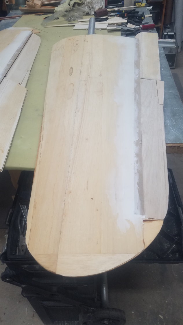
Skinning the last flap
After a lot of rework, the flap is about to be finished.
Very thin ply applied as a gap sealer strip for aileron and flap.
Rear cross member installed. Not only does it stabilize the ribs but provides for the rear wall of the wing and lower wing skin to be glued against it
Last flap installed and all wing ribs repaired.
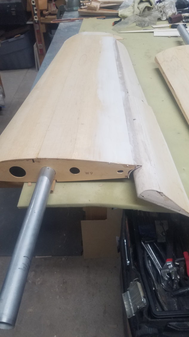
View of last flap completely skinned and sanded smooth. The gap sealer strip works great and will have sanding compound applied to its leading edge to flare it into the wing.
Finished underside of last flap.
Top of the wings, as they are getting close to being finished. Will need to install landing light and nav. lights.
Good view of gap sealer strip. Will set the flap servos tomorrow. Wings also need leading edge to be glued in and sanded to shape but will wait until bottom skin is applied.
08-07-2022, 04:57 PM
#121
Senior Member
Thread Starter
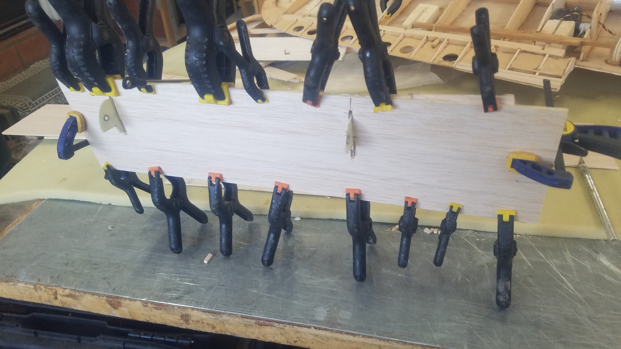
Skinning the ailerons and closing the rear of the wing. Discovered a slight warp in the wing tip and had to repair. Tomorrow will try to setup ailerons so hinge pin can be removed if require. Also, I will set the flap servos, seems like other things keep pushing it back.
Skinning the aileron. Trim tab to be added later.
Out of the clamps, but not sanded.
One side complete and on to the next side. This is one sturdy aileron; it should not flex in the wind.
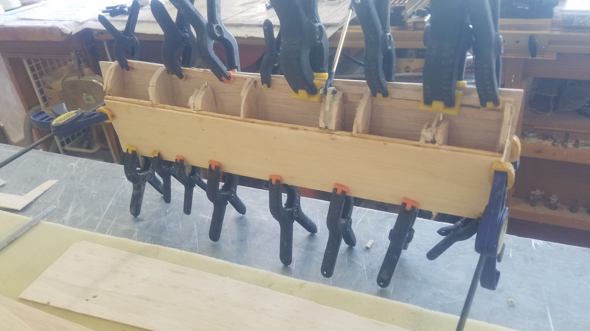
Aileron side of the rear of wing closed up.
View of flap side of the rear of the wing closed up.
The fit for the flap was very close and required minimal sanding for clearance.
Flap rear wing closer view with flap just starting to open. It has been said that take off works much better with 10 degrees of flap. This should be pretty close to the setting.
The fit for the flap is right on.
View of rear wing closure for the flap, showing where I will add some reinforcement to the opening for the push rod to the flap servo.
Saw a slight warp in the wing tip so clamped it down and reset the main spar member with added side reinforcement to correct it.
Skinning the aileron. Trim tab to be added later.
Out of the clamps, but not sanded.
One side complete and on to the next side. This is one sturdy aileron; it should not flex in the wind.
Aileron side of the rear of wing closed up.
View of flap side of the rear of the wing closed up.
The fit for the flap was very close and required minimal sanding for clearance.
Flap rear wing closer view with flap just starting to open. It has been said that take off works much better with 10 degrees of flap. This should be pretty close to the setting.
The fit for the flap is right on.
View of rear wing closure for the flap, showing where I will add some reinforcement to the opening for the push rod to the flap servo.
Saw a slight warp in the wing tip so clamped it down and reset the main spar member with added side reinforcement to correct it.
08-08-2022, 08:01 PM
#122
Senior Member
Thread Starter
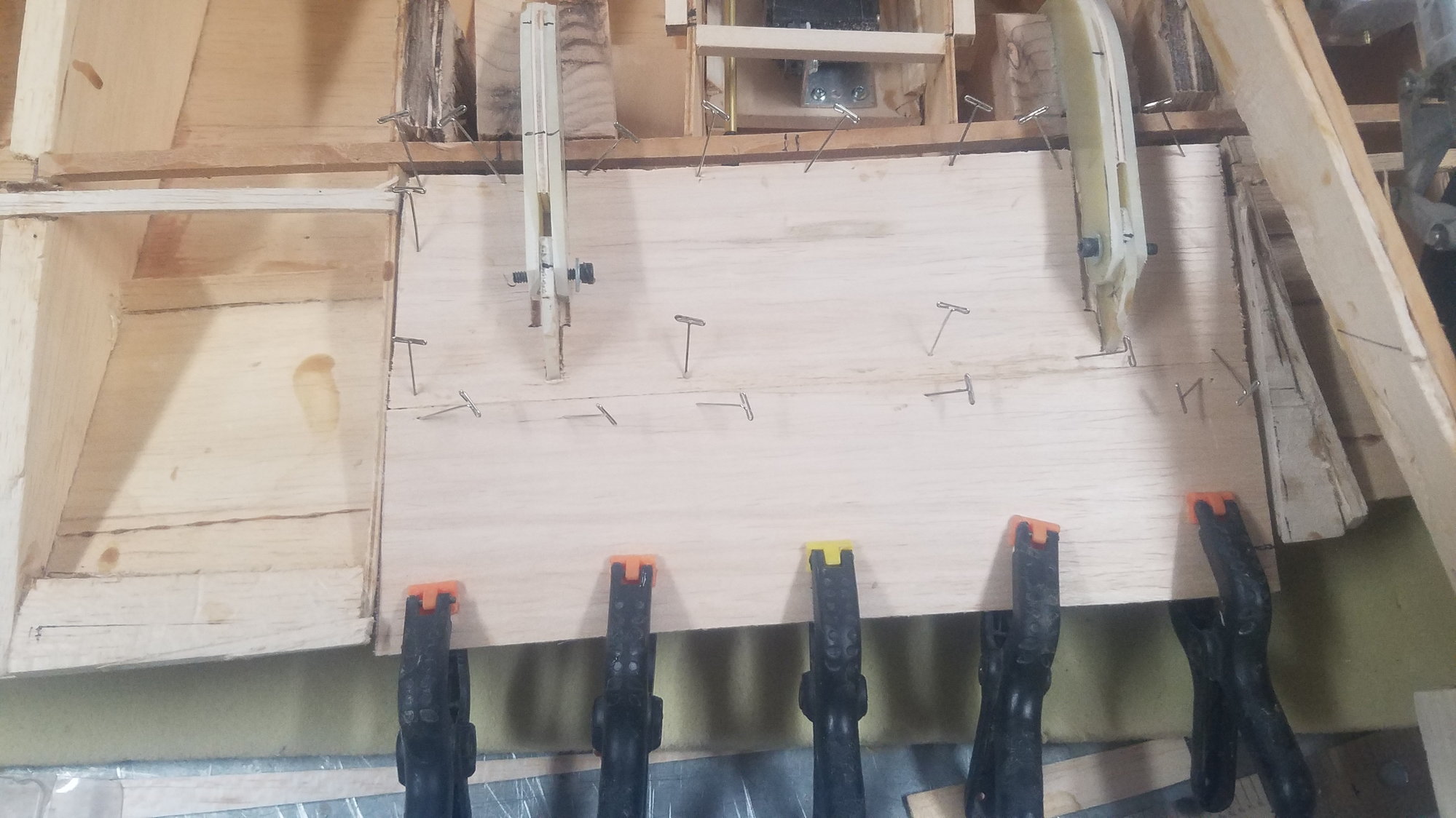
Ailerons installed and trim tabs glued in. Gap strip filled in with compound, but not sanded. Reworked the flaps due to a mismatch on lower surface to future wing skin.
Aileron installed with first idea on terminating the pin, this is not going to work. Trim tab glued in but not sanded.
The other aileron installed leaving pin come straight out to pass by the wing tip. Hope to pin it down to the tip so it can be pulled out if required. Again, trim tab glued in but not sanded.
Compound fill of gap strip.
Will leave compound dry overnight and give rough sand tomorrow, then finish fill and final sand.
Reworked flap for alignment with the wing skin once it is applied.
Same rework on the other flap. This will have to be done on the inboard flaps as well.
08-09-2022, 07:08 PM
#123
Senior Member
Thread Starter
Hooked up ailerons and flaps to the servos. Ruff sanded the gap strip on the wings.
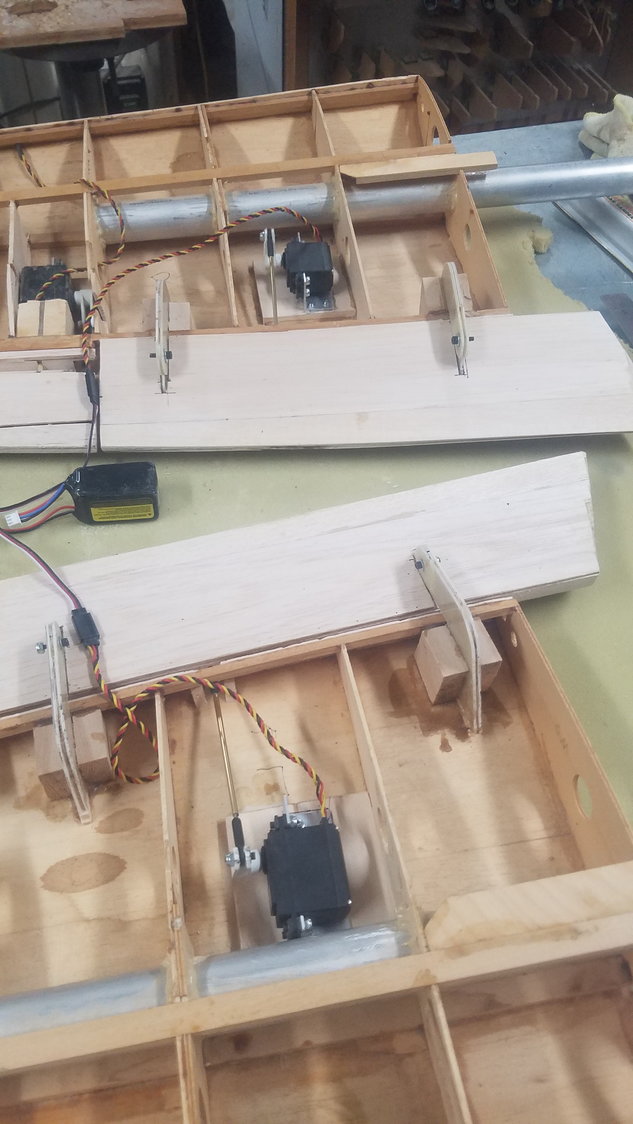
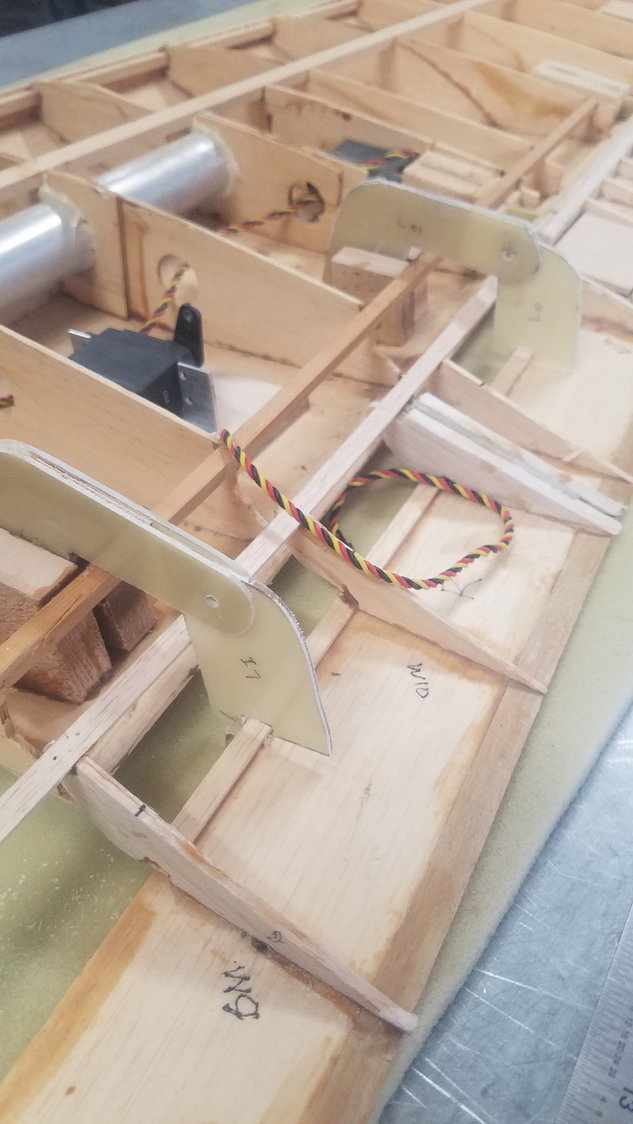
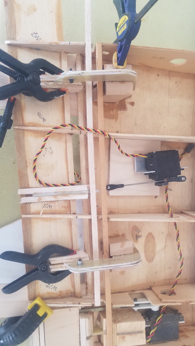
Flaps finally hooked to the servos and adjusted. Flaps closed here.
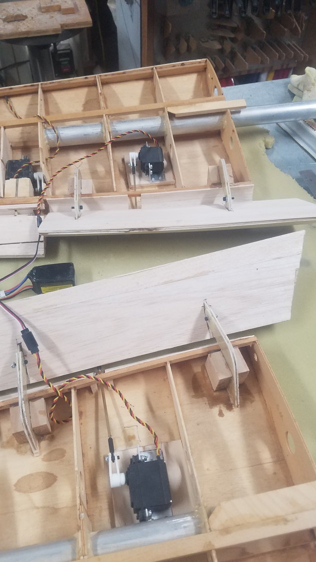
Flaps opened to 45 degrees. Note, that the servo arm is aligned with push rod to better handle the load on the servo.
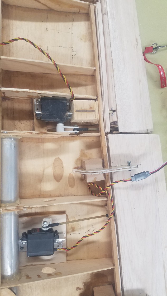
View of both aileron and flap servo on left wing.
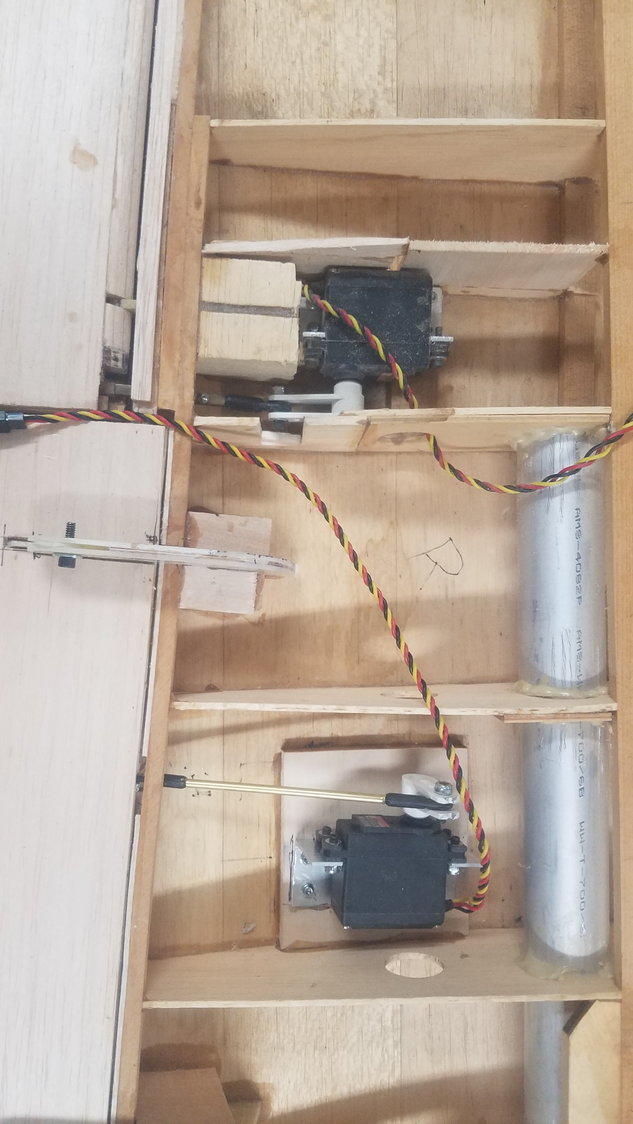
View of both aileron and flap servo on right wing.
Flaps finally hooked to the servos and adjusted. Flaps closed here.
Flaps opened to 45 degrees. Note, that the servo arm is aligned with push rod to better handle the load on the servo.
View of both aileron and flap servo on left wing.
View of both aileron and flap servo on right wing.
08-12-2022, 04:36 PM
#124
Senior Member
Thread Starter
Time to start hooking up the all the goodies. Right now, I am using 15 of the 16 channels. Created the initial list of function to radio switches, most likely will change.
Reworking inboard flap to match center section skin.
Electro Dynamics light system.
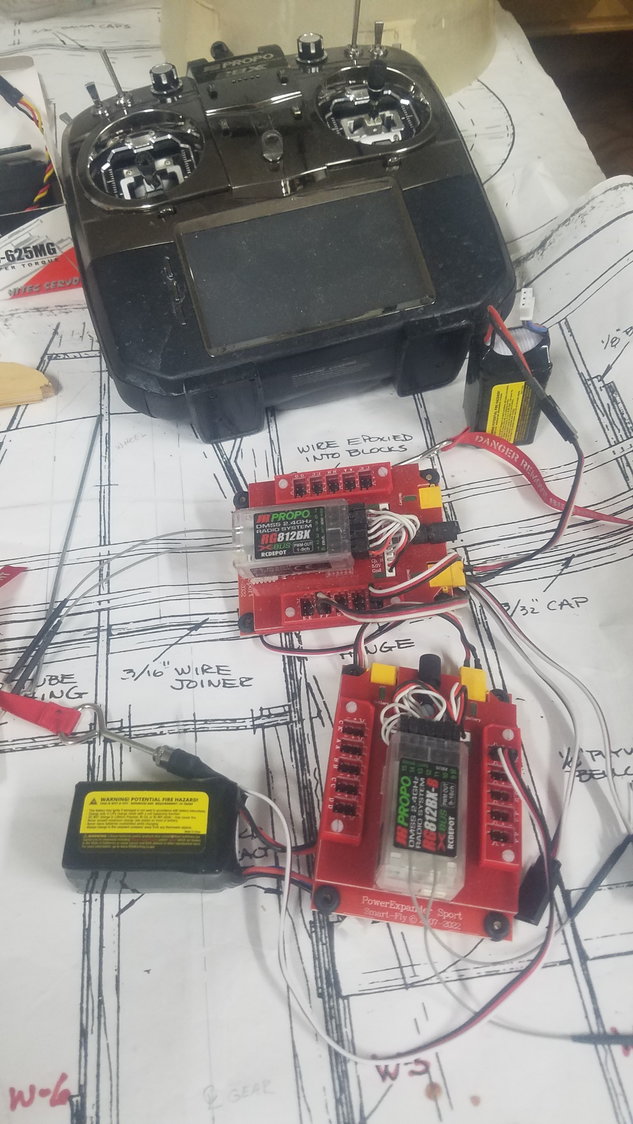
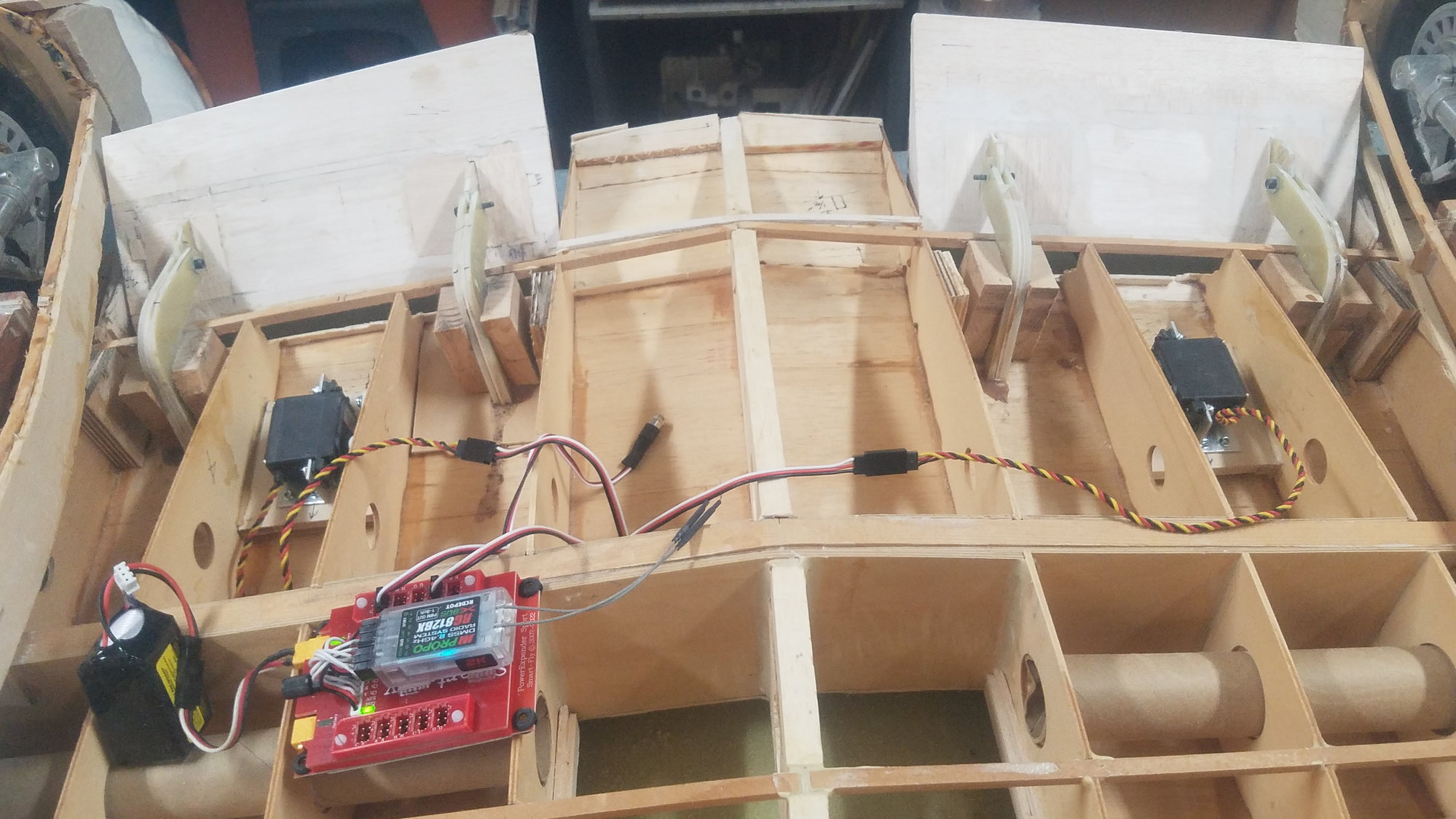
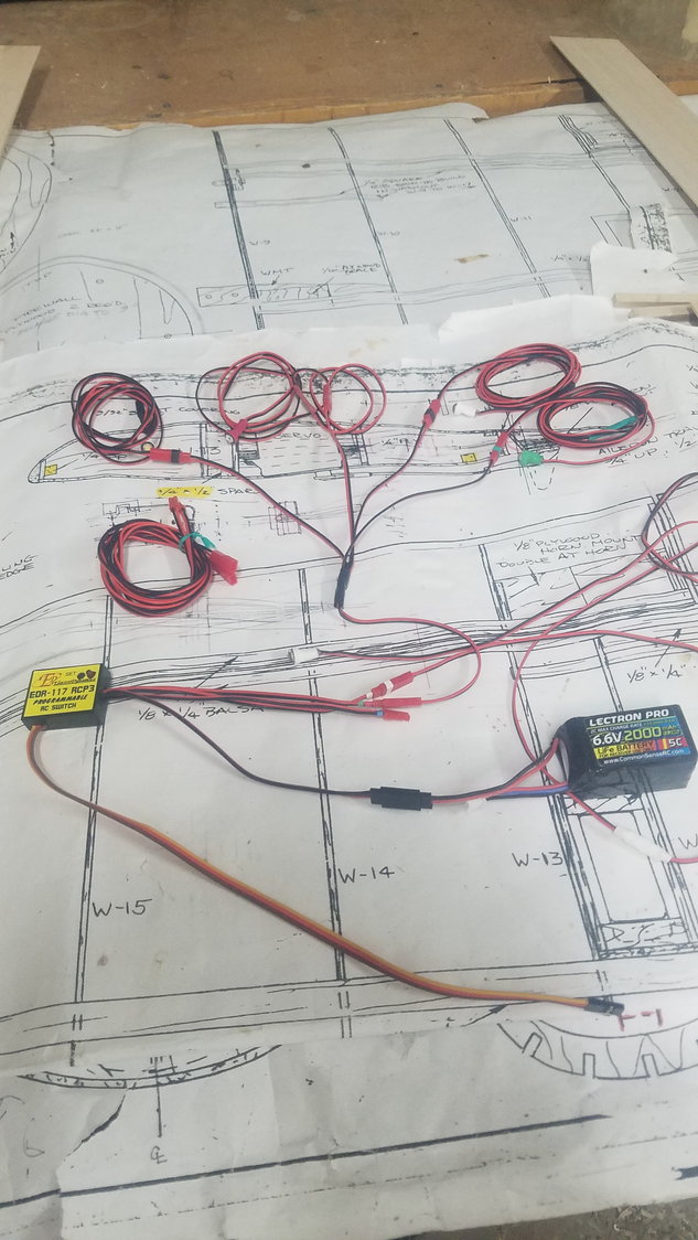
Dual receiver setup. All the non-control items will be handled by the second receiver as well as left hand side control function of throttle, ail. and flaps.
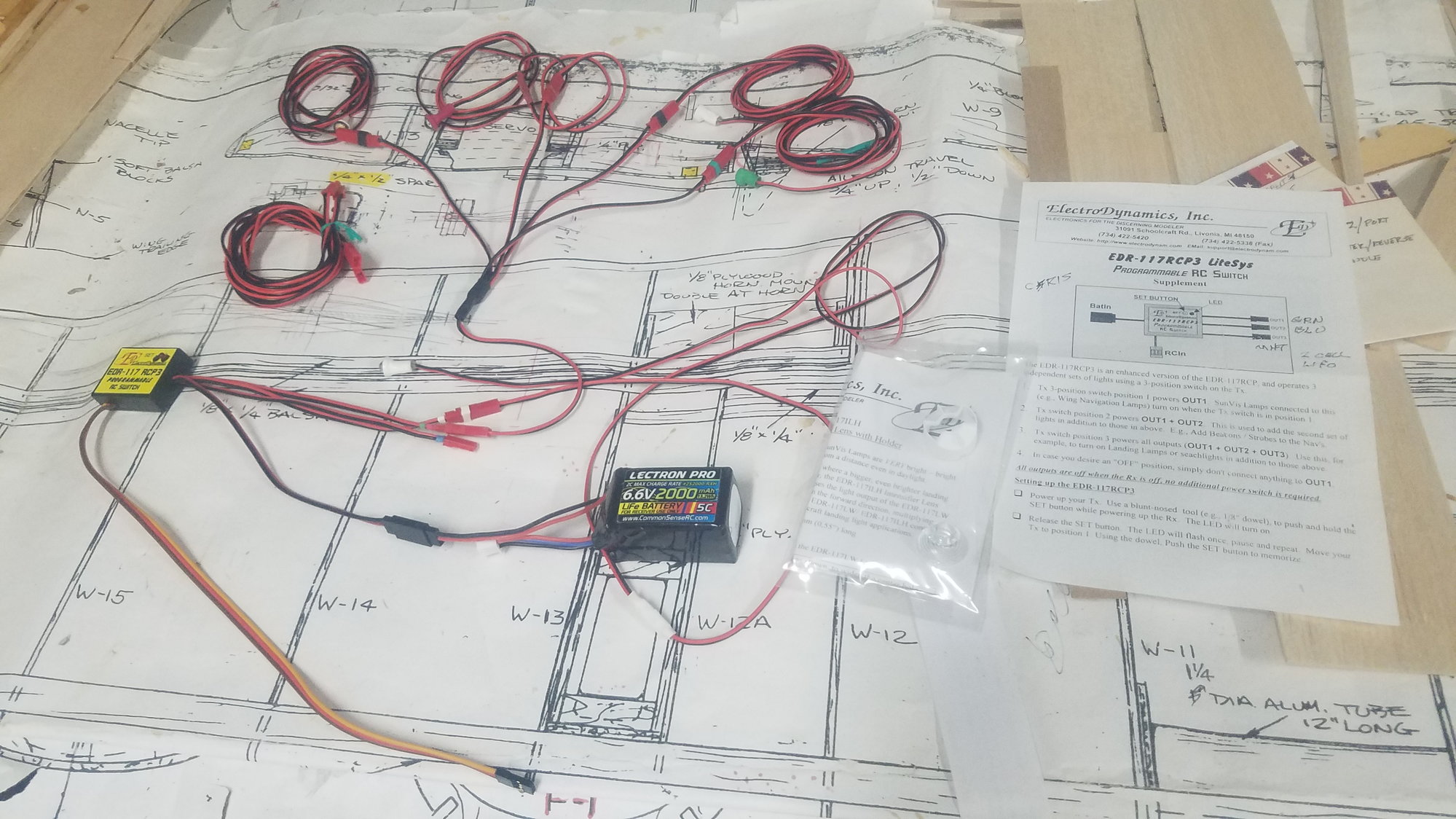
Better view of lights. This is a customized setup to deal with the two rudder white lights required for the dual vertical fins, and the landing light.
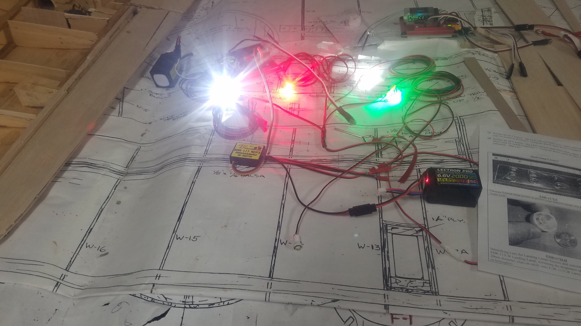
Their control switch works from a 3-position switch on the radio, with position 1 as off, position 2 as nav lights on and position 3 turns on the landing light. This is position 2 on the switch.
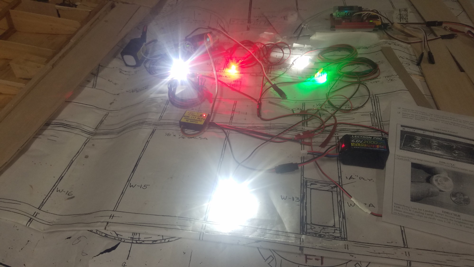
This is position 3 with landing light on. All works as advertised with no surprises and is easy to setup. They also provided the extra-long leads to the tail and out to the wing tip area. B-25 B does not use wing tip lights on the outboard edge but has lenes on both the top and bottom of the wing at the tip. More on that later.
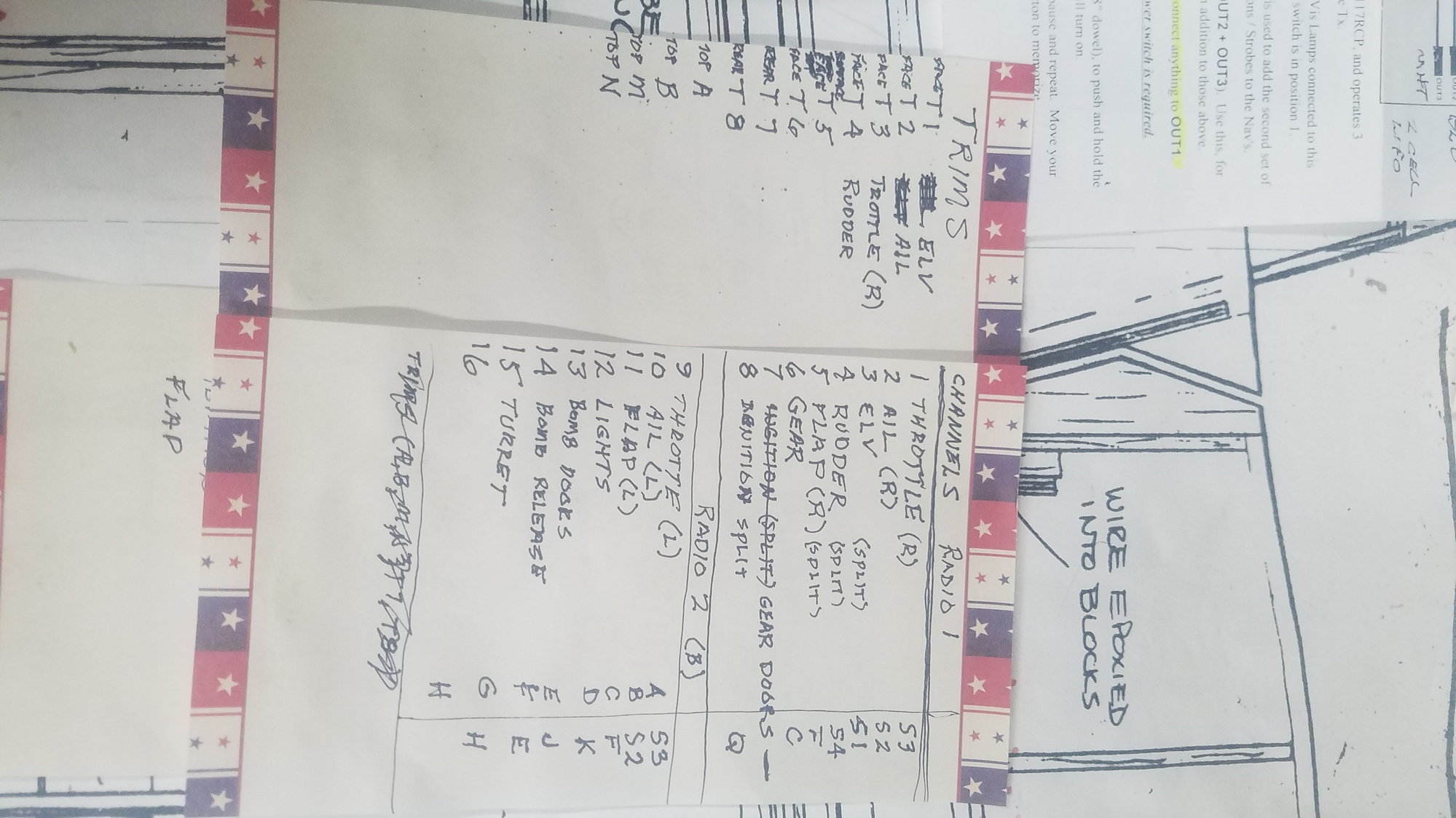
My initial list of function to switches and connections on the Smart Fly board.
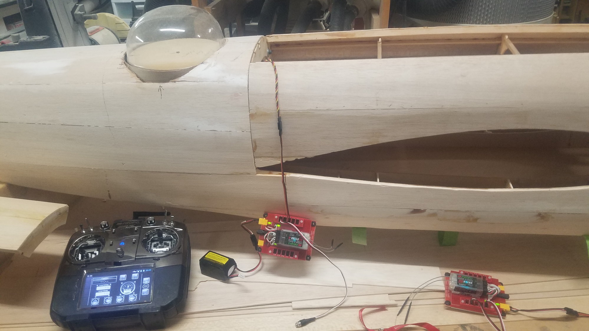
Turret servo hooked up and radio programmed to the correct channel.
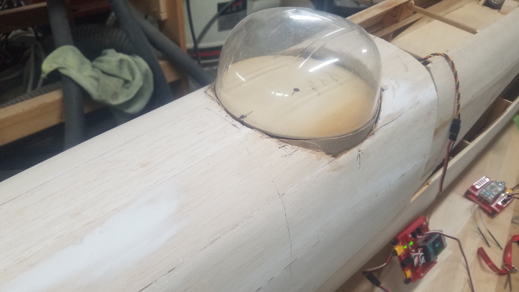
Rotational function attached to right hand knob on the radio, so turret rotates as knob is turned. Here is approximate center.
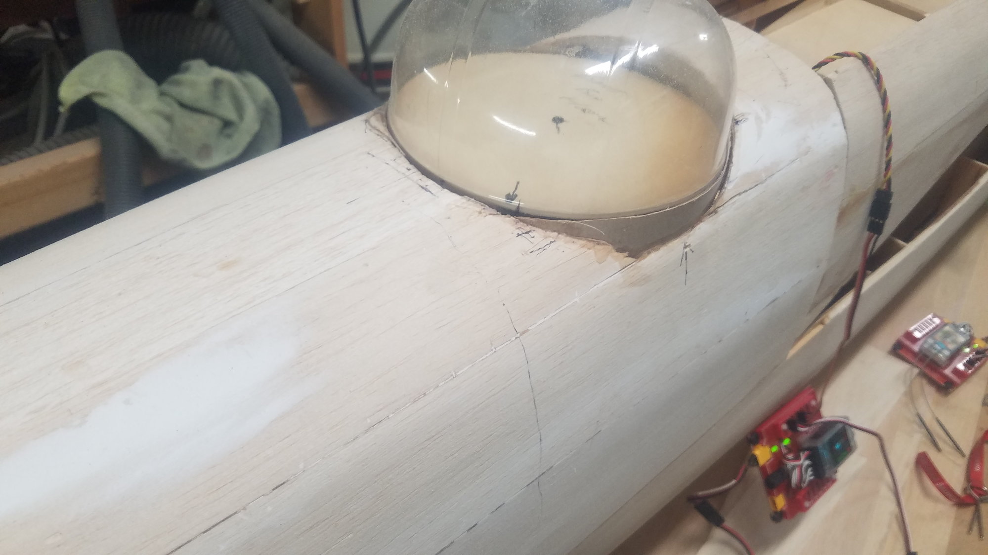
Rotated right.
Rotated left. Will need to reset the center position on the servo.
Reworking inboard flap to match center section skin.
Electro Dynamics light system.
Dual receiver setup. All the non-control items will be handled by the second receiver as well as left hand side control function of throttle, ail. and flaps.
Better view of lights. This is a customized setup to deal with the two rudder white lights required for the dual vertical fins, and the landing light.
Their control switch works from a 3-position switch on the radio, with position 1 as off, position 2 as nav lights on and position 3 turns on the landing light. This is position 2 on the switch.
This is position 3 with landing light on. All works as advertised with no surprises and is easy to setup. They also provided the extra-long leads to the tail and out to the wing tip area. B-25 B does not use wing tip lights on the outboard edge but has lenes on both the top and bottom of the wing at the tip. More on that later.
My initial list of function to switches and connections on the Smart Fly board.
Turret servo hooked up and radio programmed to the correct channel.
Rotational function attached to right hand knob on the radio, so turret rotates as knob is turned. Here is approximate center.
Rotated right.
Rotated left. Will need to reset the center position on the servo.
08-14-2022, 07:45 PM
#125
Senior Member
Thread Starter
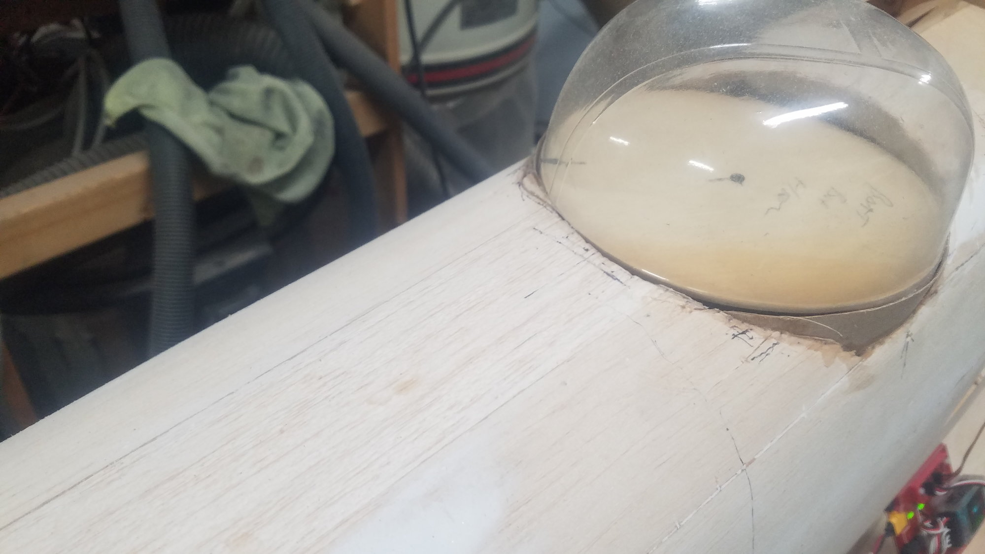
Preparing for nav light location, ail. hinge pin stop, wire tube creation and install and landing light location.
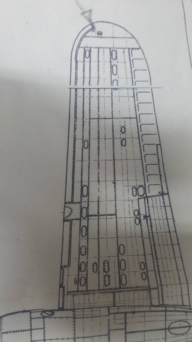
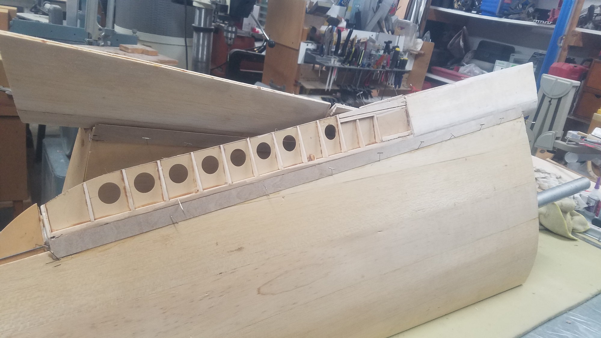
The B-25B has nav lights flush on the top and bottom of the wing as shown (arrow points to the location). Note, the location of the landing light, which is located in both wings.
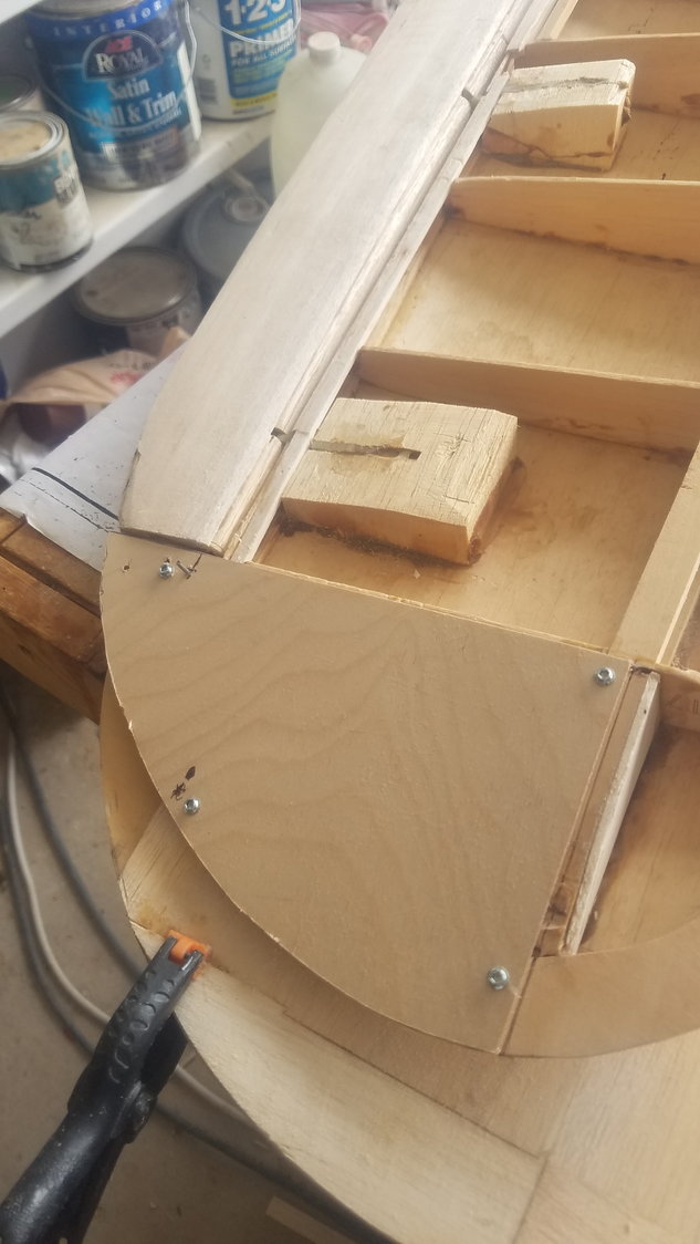
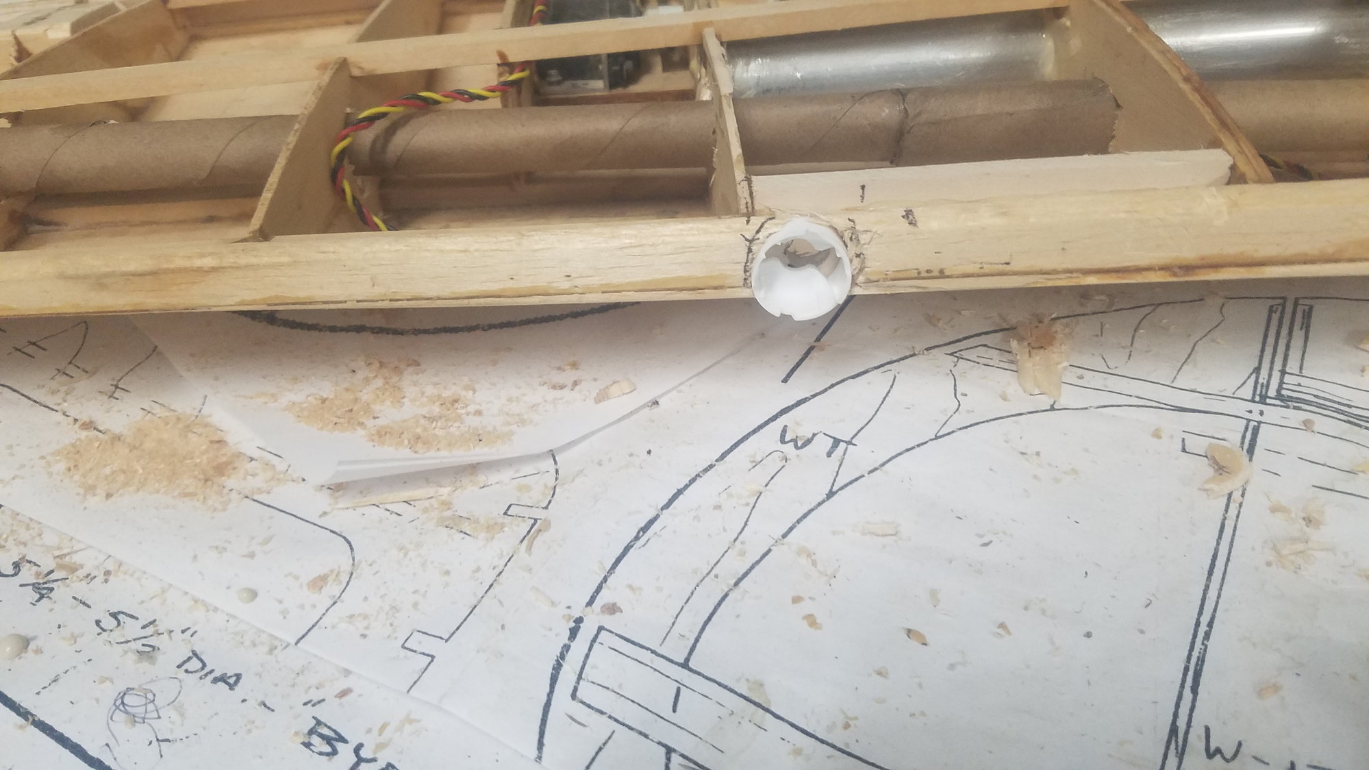
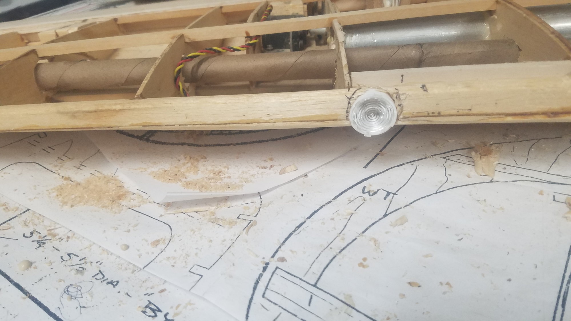
This area is where the nav light will be located and will be removable to be able to service the light. This also provided a stop for the ail. hinge pin which protrudes through a hole in the ply, simple, but it works.
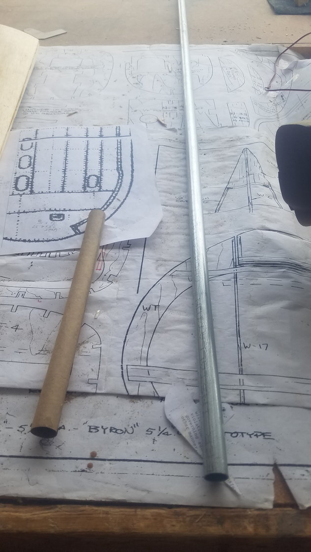
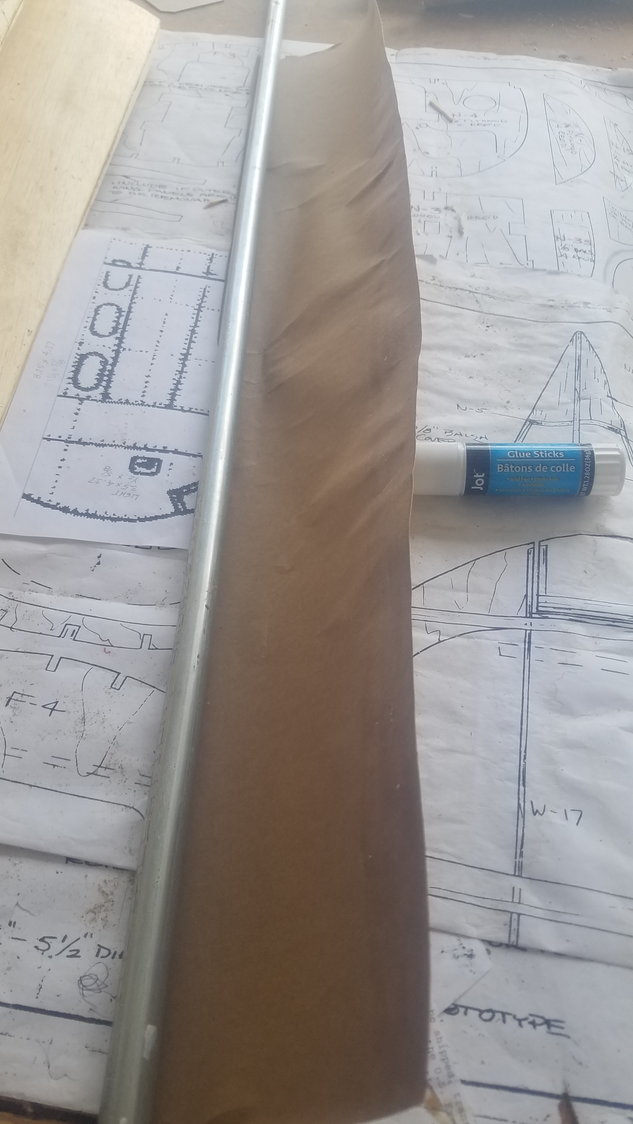
First attempt at rolling my own wiring tubes. Found I need to wrap paper at an angle to make this work. Using a 1/2" piece of conduit as the form. I also used a glue stick to make the paper attach to itself. A short piece of tube can wrap straight but anything longer takes a bias wrap.
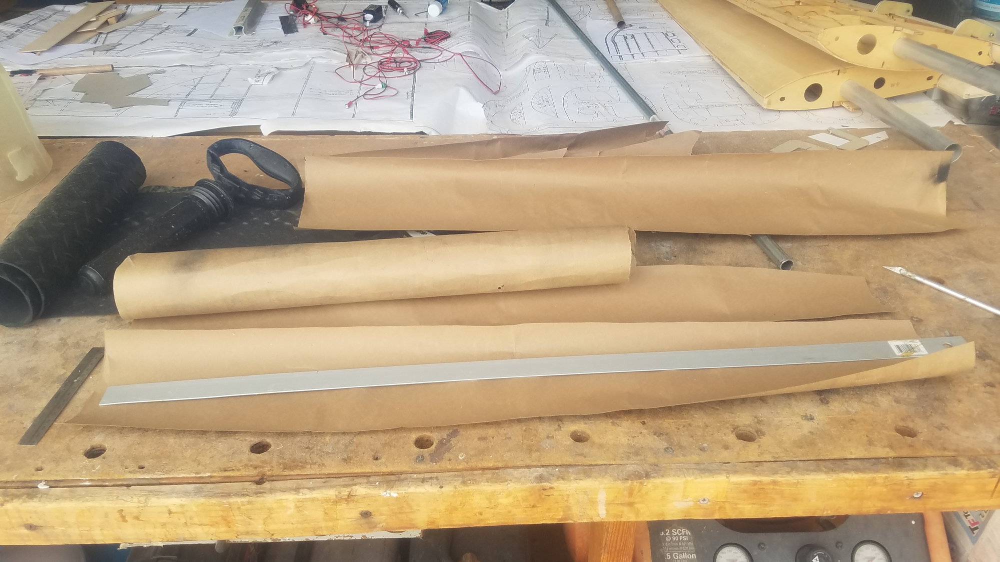
I cut a 6" wide strip to wrap. I found a 3" wide strip worked better to wrap on the bias.
This did not work for a long tube.
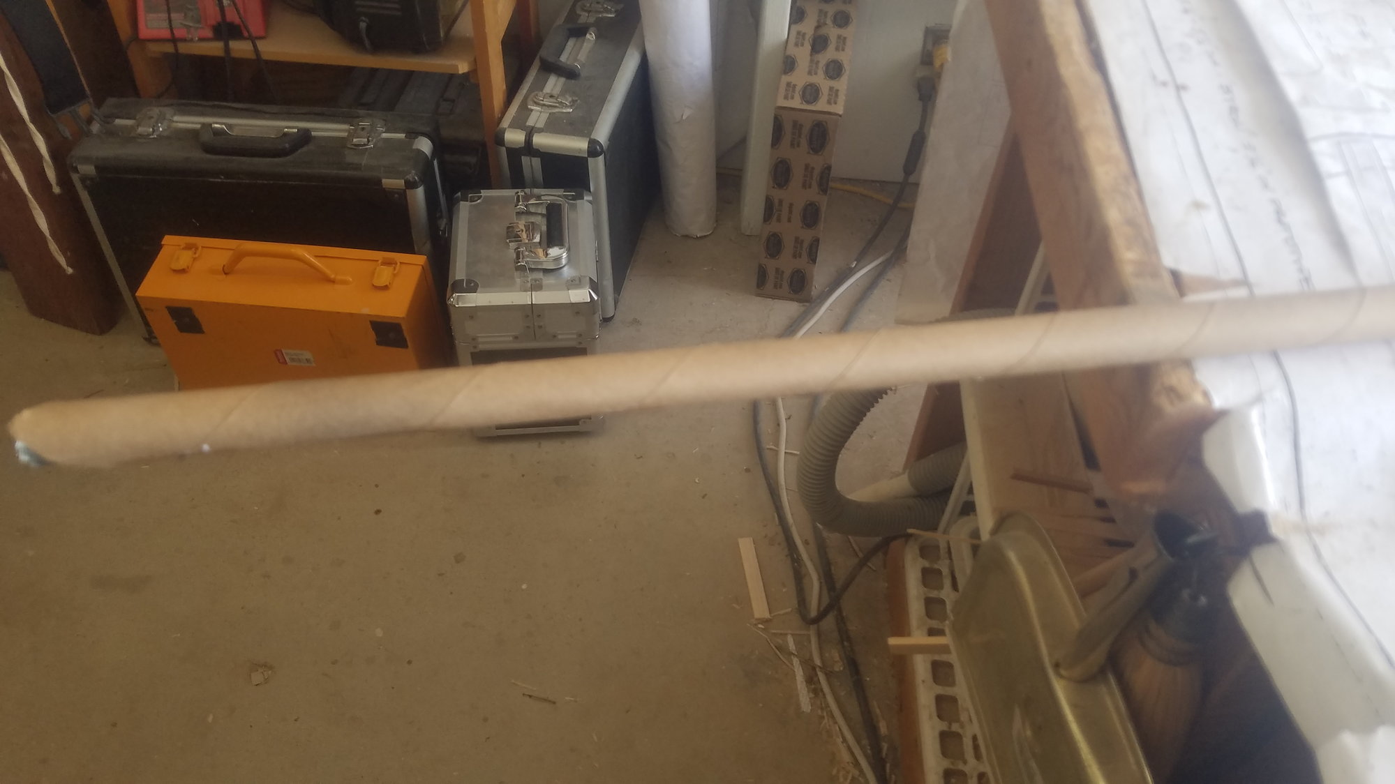
Bias wrap worked. Also was able to join two pieces to get correct length.
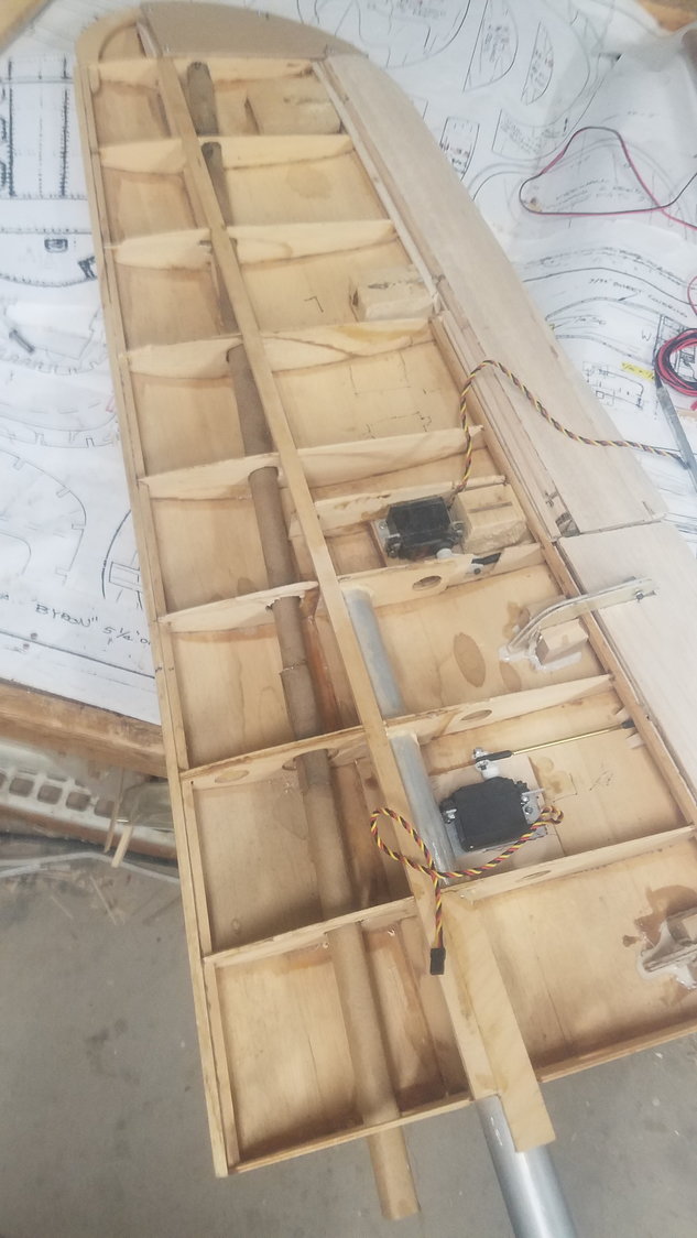
Cut holes in ribs to install the tube at an angle to get to the nav. light location.
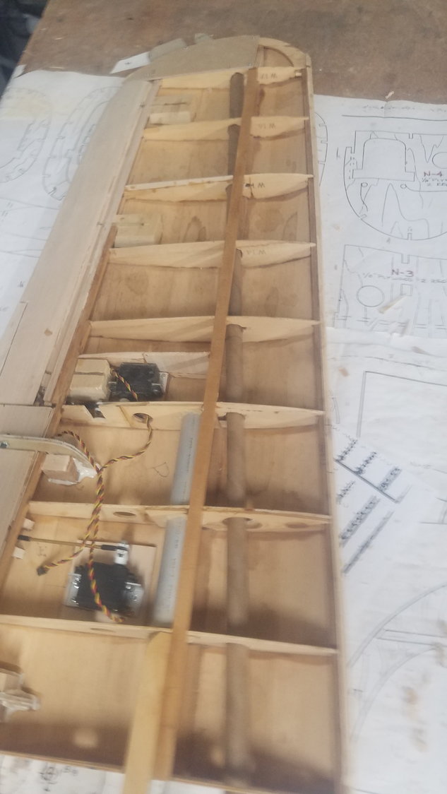
Tube installed in other wing. The tube will handle the wires for the ail., flap, nav and landing light.
Landing light enclosure temporarily installed. Cut bass wood reinforcement to correct where front 1/4" spruce spar was cut.
Landing light enclosure and lens temporarily installed.
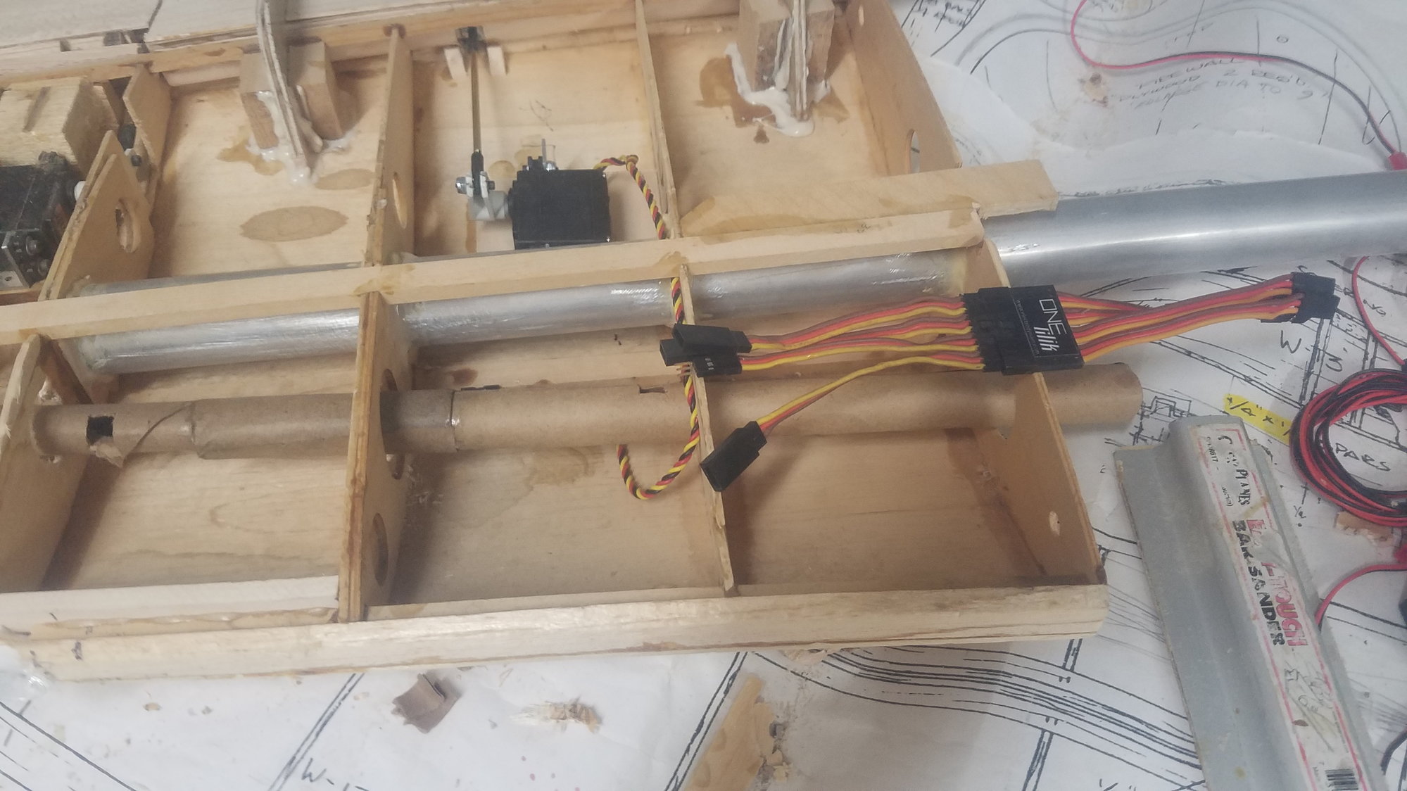
I plan to use a 4 lead One-Clik Multi-Connex to do all the connections for each wing.
The B-25B has nav lights flush on the top and bottom of the wing as shown (arrow points to the location). Note, the location of the landing light, which is located in both wings.
This area is where the nav light will be located and will be removable to be able to service the light. This also provided a stop for the ail. hinge pin which protrudes through a hole in the ply, simple, but it works.
First attempt at rolling my own wiring tubes. Found I need to wrap paper at an angle to make this work. Using a 1/2" piece of conduit as the form. I also used a glue stick to make the paper attach to itself. A short piece of tube can wrap straight but anything longer takes a bias wrap.
I cut a 6" wide strip to wrap. I found a 3" wide strip worked better to wrap on the bias.
This did not work for a long tube.
Bias wrap worked. Also was able to join two pieces to get correct length.
Cut holes in ribs to install the tube at an angle to get to the nav. light location.
Tube installed in other wing. The tube will handle the wires for the ail., flap, nav and landing light.
Landing light enclosure temporarily installed. Cut bass wood reinforcement to correct where front 1/4" spruce spar was cut.
Landing light enclosure and lens temporarily installed.
I plan to use a 4 lead One-Clik Multi-Connex to do all the connections for each wing.