


125% (1/4 scale) Anderson TA-152H


 05-09-2015, 04:26 PM
#354
I cleaned up the perimeter of the stab molds then popped the plugs out and gave them a good wash in the sink.
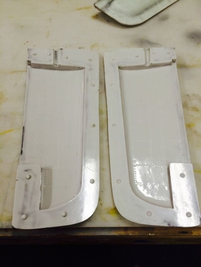
And a closeup of the details:
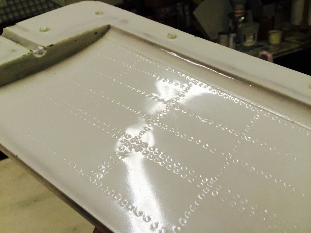
I also popped the vertical stab molds free as well and also cleaned those up.
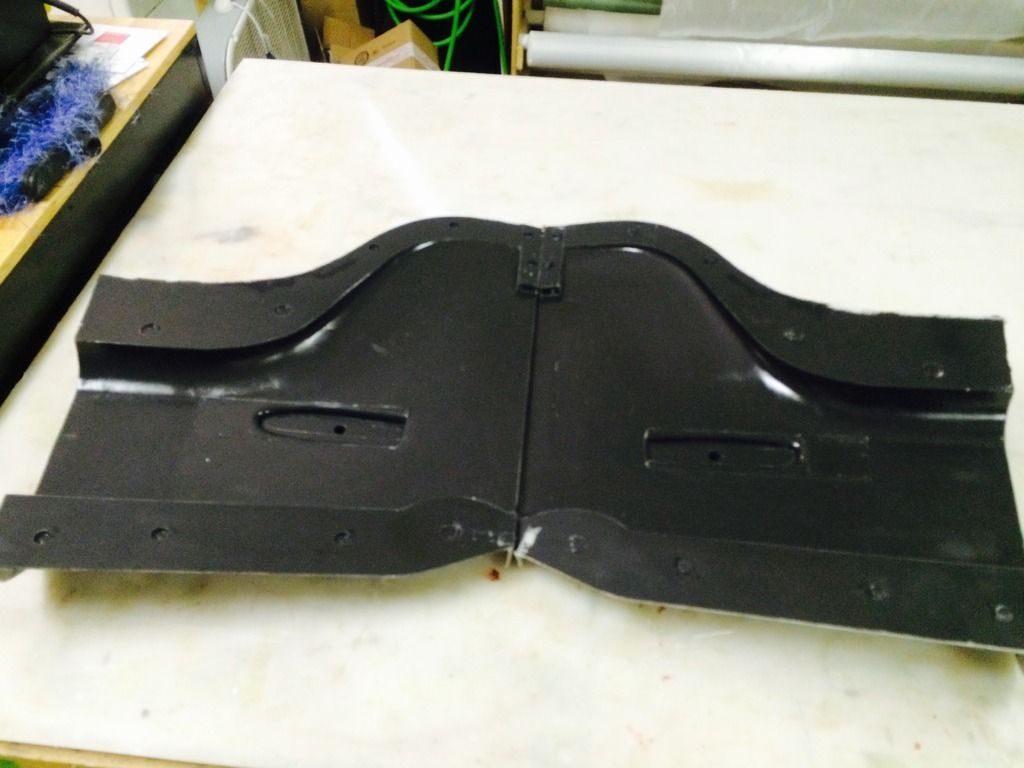
Here is a shot looking in from the front with the stab tube inserted through the locator holes i molded in:
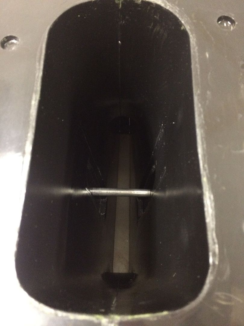
Then once all that was done, i put the vert stab molds back on the plug and then drilled all the holes for clamping the molds together. I need to order around 150 clinch nuts now.
05-10-2015, 01:13 PM
#355
Fuselage mold has been removed, cleaned and currently in the process of being prepped for frekote mold release. Here are a few photo's pre cleaning.
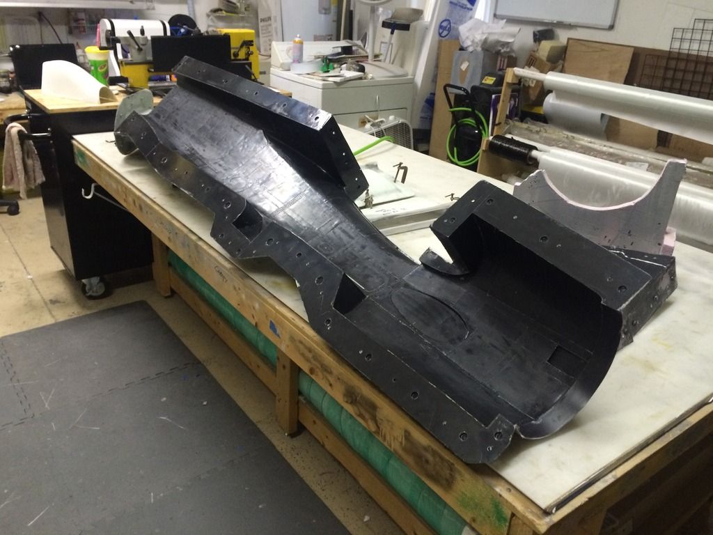
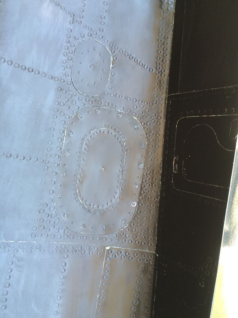
Closeup of the button head slotted screws in the mold:

Closeup of more of the details:
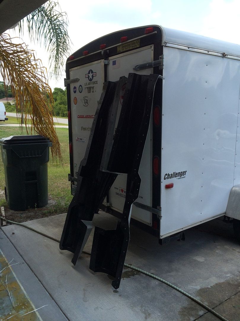
Here is the mold minus the tail section standing up beside my trailer after have the wax and Pva washed off:
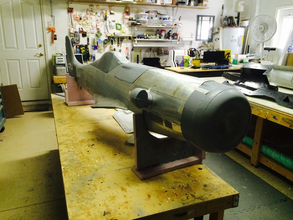
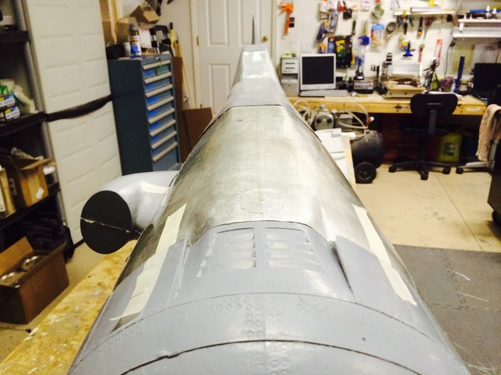
Since I now have the small parts molded, I can see how well everything fit (i don't think I checked before molding the fuse).You can also see that I attached the windscreen plug to the fuse plug in prep for detailing and molding:


Closeup of the button head slotted screws in the mold:

Closeup of more of the details:

Here is the mold minus the tail section standing up beside my trailer after have the wax and Pva washed off:

Since I now have the small parts molded, I can see how well everything fit (i don't think I checked before molding the fuse).You can also see that I attached the windscreen plug to the fuse plug in prep for detailing and molding:


 05-12-2015, 05:49 PM
#357


Join Date: Jul 2012
Location: Missouri
Posts: 1,127
Likes: 0
Received 0 Likes
on
0 Posts
Question Thomas
I understand you will be vacuum bagging the fuse halves ( and everything else my guess)
When you lay the glass in the fuse half's. Will you run the glass up and over the parting plane and press it down 90 deg's flat on parting plane ?
If not, how do you deal with the glass layup at the fuse seam/ parting plane ?
Hope my question makes sense .
Kevin
05-13-2015, 05:01 PM
#360
Made a good bit of progress today, yesterday was spent insulating the garage door..
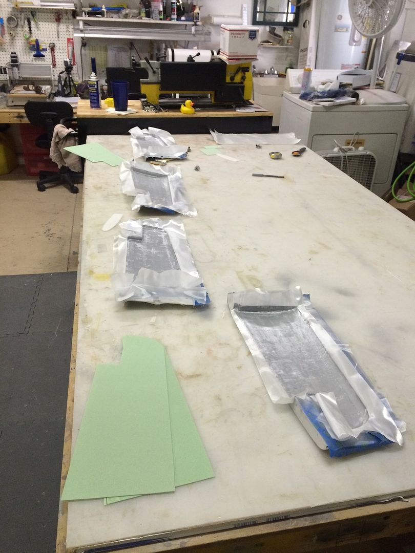
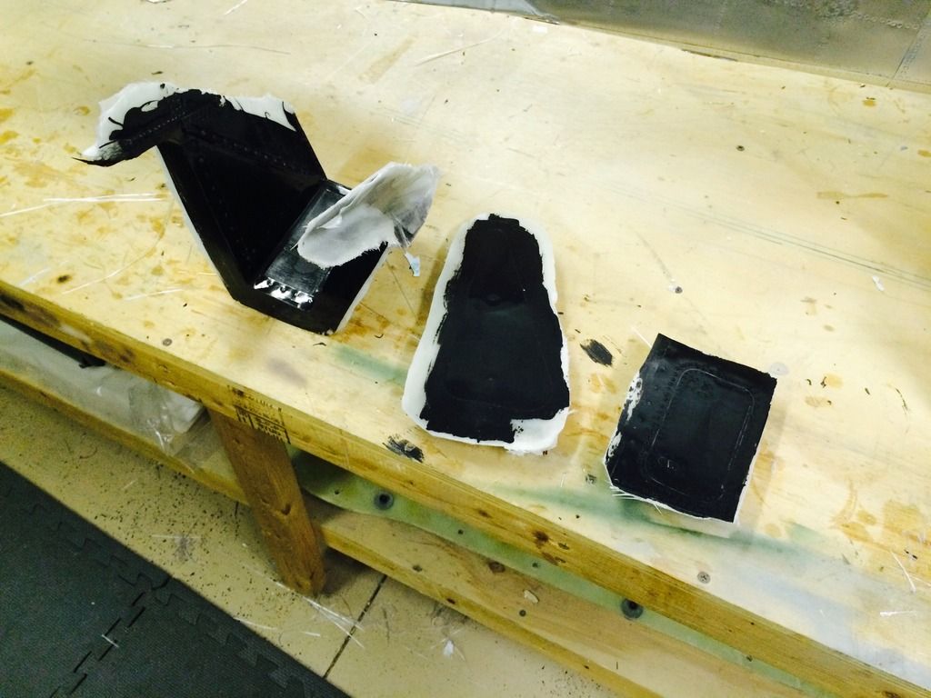
First up was doing some molds of the windscreen and some various hatches along the fuselage and tail so as to have molded in hatch recess' and flanges in the parts.
The two hatch mold layups are very thin at only around .030" total thickness. So on order to keep them in the proper shape, these will get some backers on them. These will be hand layups and not vacuum bagged so the backing structure wont be an issue.
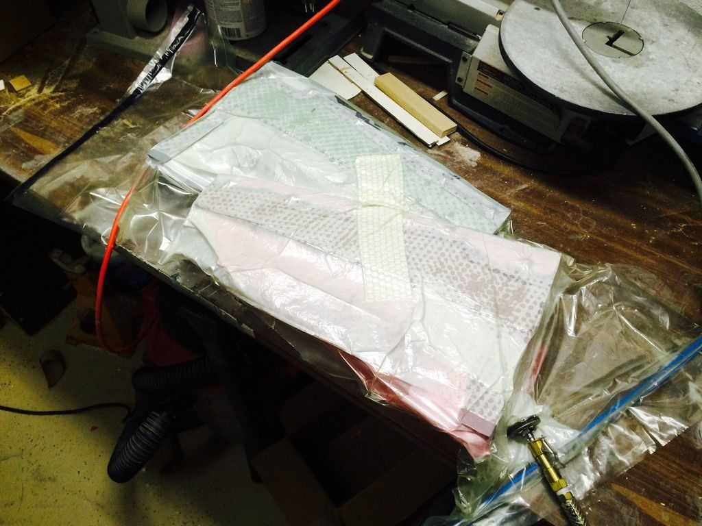
I also got the first set of horizontal stab skins thrown in the industrial suck bags.

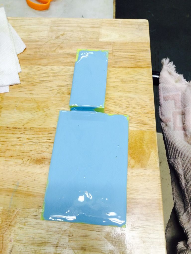
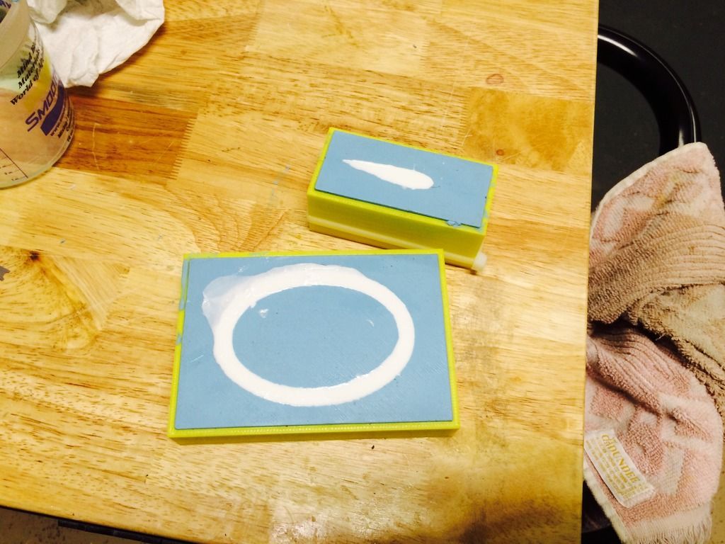
My silicon rubber and casting resin also arrived today so i set out learning something new. I followed Don's recommendation of brushing on a layer of the molding silicon before pouring it and here is what they two molds look like inside the 3D printed mold boxes after pouring the rubber.
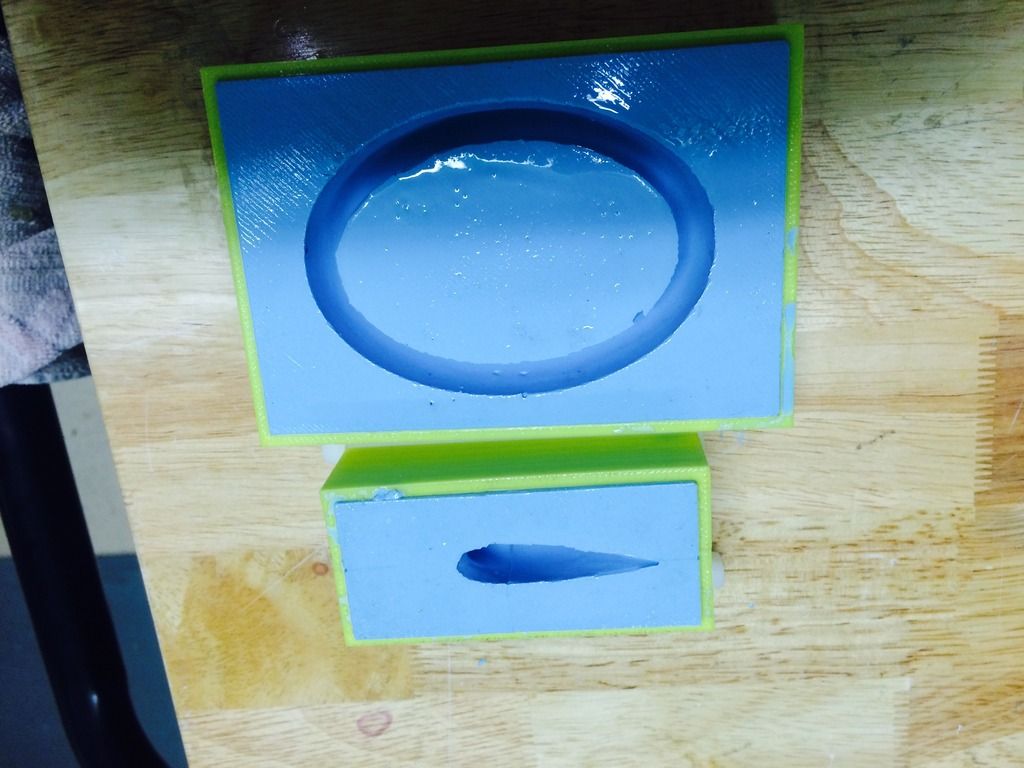
Then after about 2 hours, i peeled the rubber from the molding boxes. The smaller one required the box to be cut in two length wise, then the rubber mold was cut down the long sides vertically so as to removed the plug. The molding box sides are then strapped to the rubber mold with some zip ties to hold it back tight together for pouring ghe casting resin.
This is the first time ive done these kind of molds and they turned out pretty good i think.
First up was doing some molds of the windscreen and some various hatches along the fuselage and tail so as to have molded in hatch recess' and flanges in the parts.


The two hatch mold layups are very thin at only around .030" total thickness. So on order to keep them in the proper shape, these will get some backers on them. These will be hand layups and not vacuum bagged so the backing structure wont be an issue.
I also got the first set of horizontal stab skins thrown in the industrial suck bags.


My silicon rubber and casting resin also arrived today so i set out learning something new. I followed Don's recommendation of brushing on a layer of the molding silicon before pouring it and here is what they two molds look like inside the 3D printed mold boxes after pouring the rubber.

Then after about 2 hours, i peeled the rubber from the molding boxes. The smaller one required the box to be cut in two length wise, then the rubber mold was cut down the long sides vertically so as to removed the plug. The molding box sides are then strapped to the rubber mold with some zip ties to hold it back tight together for pouring ghe casting resin.
This is the first time ive done these kind of molds and they turned out pretty good i think.
 05-14-2015, 04:11 PM
#361
The backings for the hatch molds were cut, attached and then the molds removed.
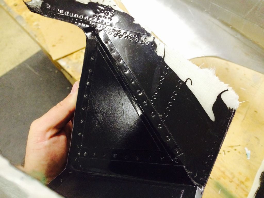
I also washed all the mold release off. Here is a closeup of the canopy frame mold surface.
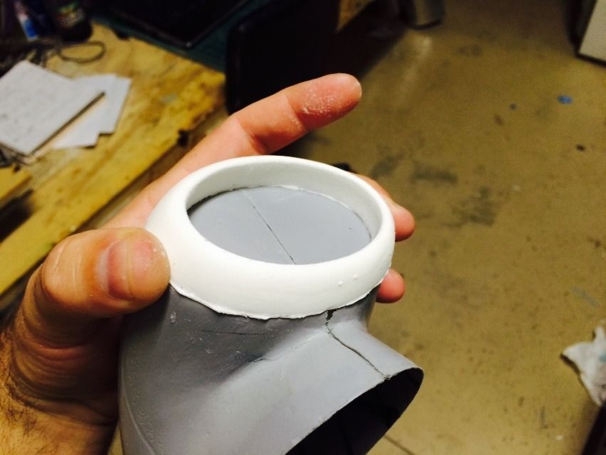
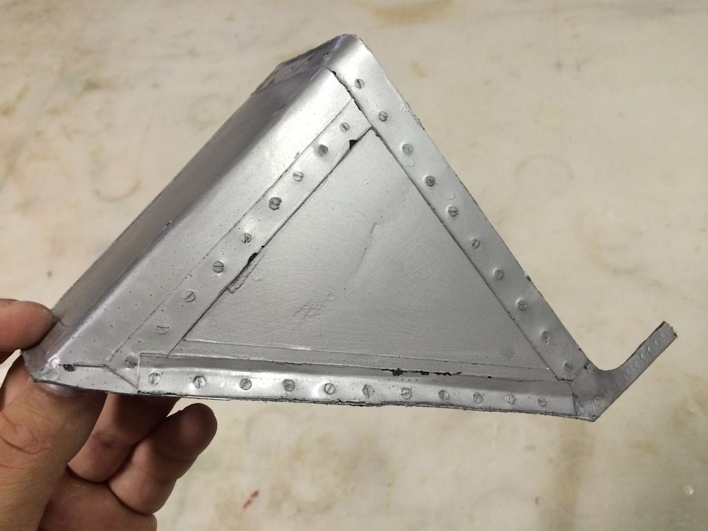
I also poured the first resin cast parts. Here they are half way through the cure.
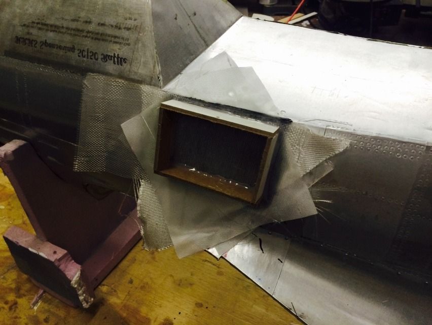
The cockpit air scoop ended up with a little air bubble in two places so im trying out a different way of pouring it to eliminate that.
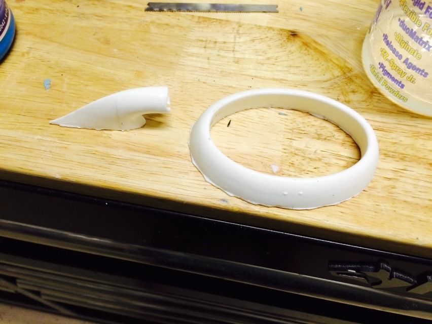
Here is the scoop lip after just a small amount of flattening on some 60grit paper. The fit is really good and with just a little finish sanding, it'll be perfect. Supposedly there is some sort of dye you can put in this stuff to change its color, i may get some of that and mix it in to try and get it to match the tan color is really is.


I also washed all the mold release off. Here is a closeup of the canopy frame mold surface.

I also poured the first resin cast parts. Here they are half way through the cure.

The cockpit air scoop ended up with a little air bubble in two places so im trying out a different way of pouring it to eliminate that.

Here is the scoop lip after just a small amount of flattening on some 60grit paper. The fit is really good and with just a little finish sanding, it'll be perfect. Supposedly there is some sort of dye you can put in this stuff to change its color, i may get some of that and mix it in to try and get it to match the tan color is really is.
 05-16-2015, 01:28 PM
#362
After taking a few measurements and cutting some test pieces to check the fit, the internal structure for the horizontal stab was cut from a laminate panel:
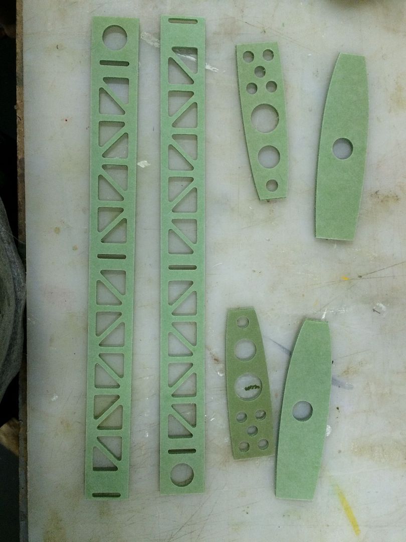
Stab TE spar test fit in the stab halves. The narrow vertical slots are precut and positioned in this panel for the CNC cut G-10 hinge pieces that will be included with the kit:
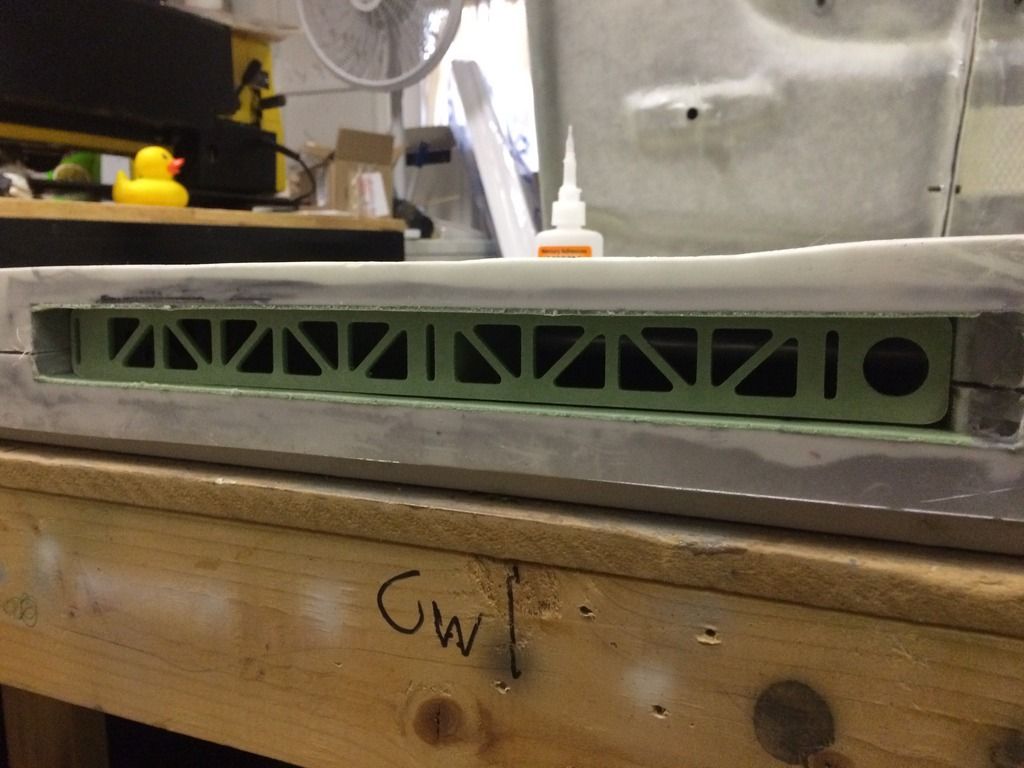
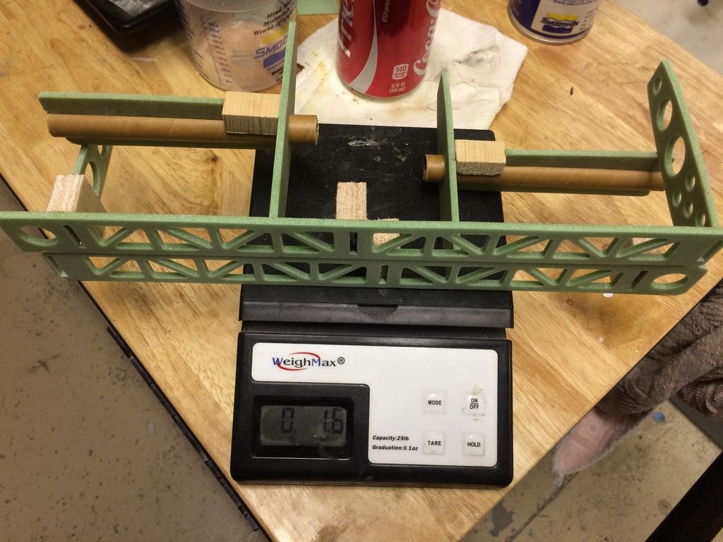
The remaining structure, hinge blocks and tube attachment blocks were then installed. You'll also notice a laminate panel sheer web added above the centerline of the stab tube socket.

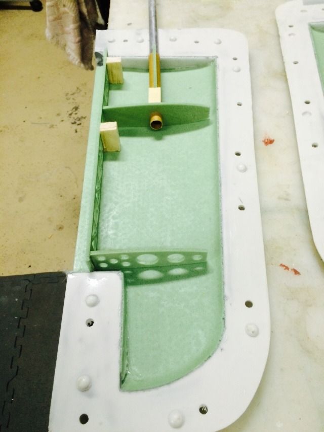
Then the entire internal structure was weighted. 1.6oz for both stab halves. I can live with that:
Then the halves were joined. All parts are closed with a combination of Carbon fiber tow and Hysol adhesives. While many use the home-made concoction of epoxy, milled/chopped fiber and some filler, i don't. Personally i feel that the inherent difficulties in keeping a consistent mixture is far more time consuming than just spending the money on a proper adhesive.


Stab TE spar test fit in the stab halves. The narrow vertical slots are precut and positioned in this panel for the CNC cut G-10 hinge pieces that will be included with the kit:

The remaining structure, hinge blocks and tube attachment blocks were then installed. You'll also notice a laminate panel sheer web added above the centerline of the stab tube socket.


Then the entire internal structure was weighted. 1.6oz for both stab halves. I can live with that:

Then the halves were joined. All parts are closed with a combination of Carbon fiber tow and Hysol adhesives. While many use the home-made concoction of epoxy, milled/chopped fiber and some filler, i don't. Personally i feel that the inherent difficulties in keeping a consistent mixture is far more time consuming than just spending the money on a proper adhesive.
 05-16-2015, 06:56 PM
#363
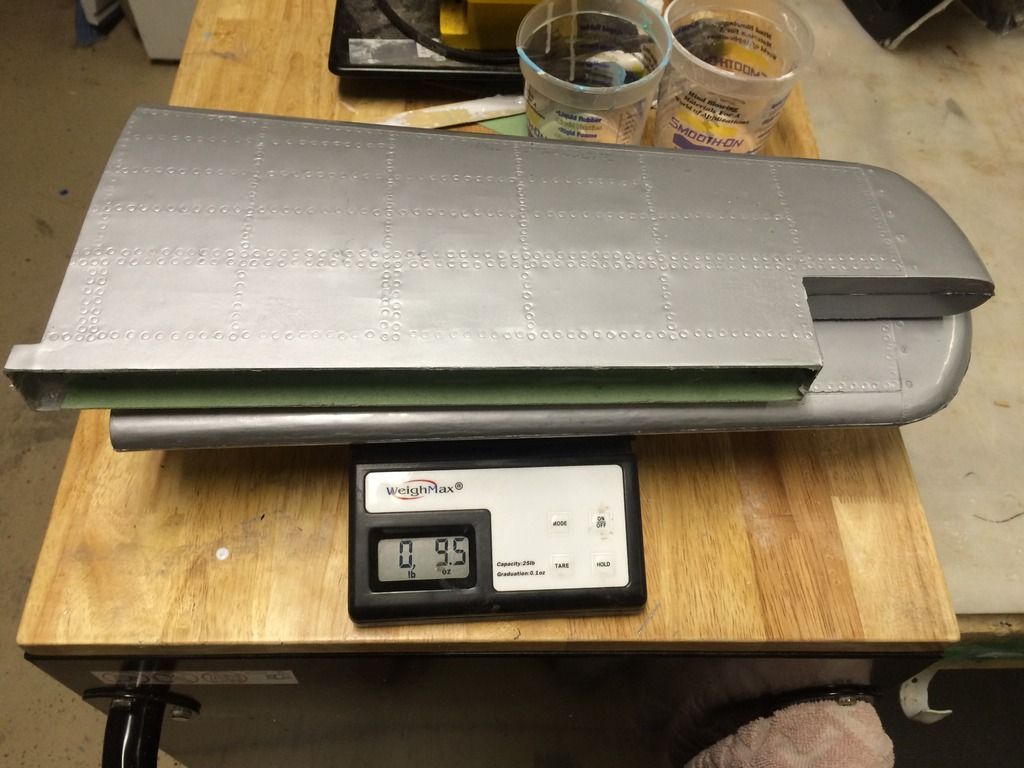
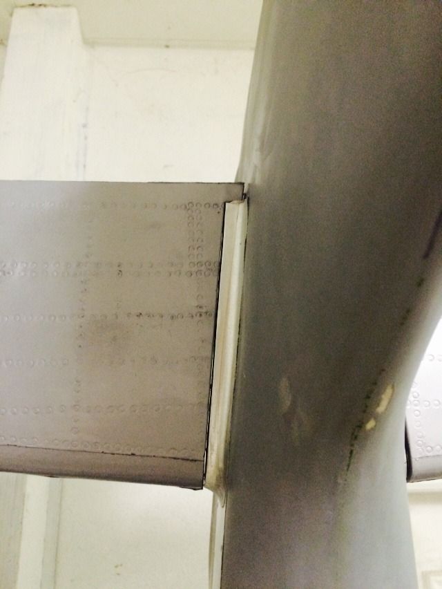
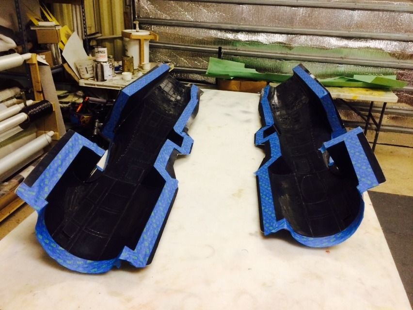
Stabs are now out of the molds. I am very pleased with what came out of the molds and am glad i took the time. Finished weight is a few ounces lighter than what the plugs were Before glassing, so i bet there is a good 4-6 ounce weight savings in the tail with the composite stabs. All that will be required to have these ready for paint is to dress up the seam lines and install the elevator hinges and these are paint ready!
Enough of the babbling, enjoy the pics.
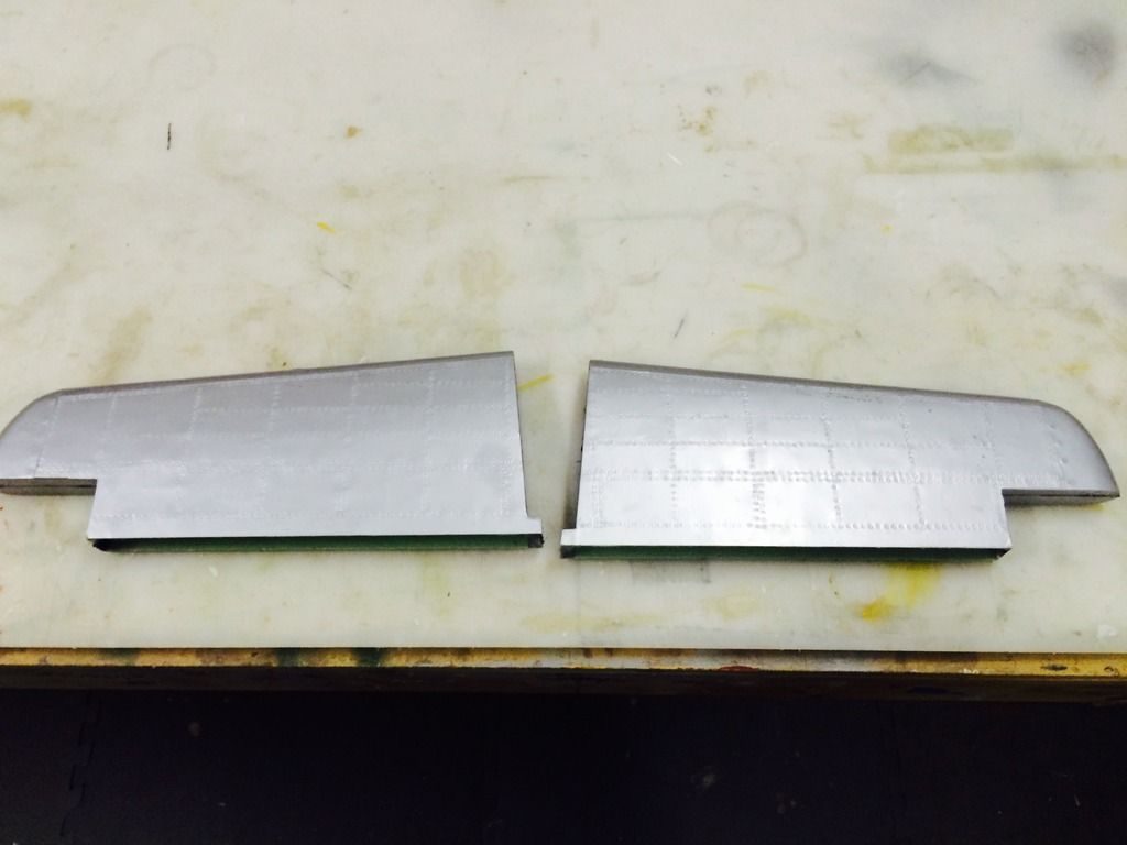
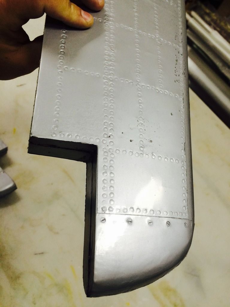
Right side stab molding on the fuse plug. The fit will be perfect once the remainder of the seam flashing is removed.
Enough of the babbling, enjoy the pics.


Right side stab molding on the fuse plug. The fit will be perfect once the remainder of the seam flashing is removed.
 05-17-2015, 02:14 PM
#364
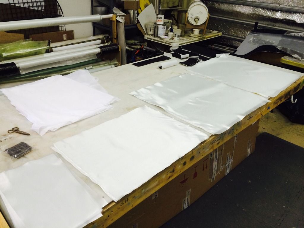
Time to make some templates. First up was using some thin brown packing paper to make up the fuse template. I use magnets to keep the paper from shifting and cut them slightly oversized.

This was then removed and transferred to a thin plastic.
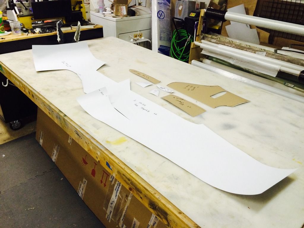
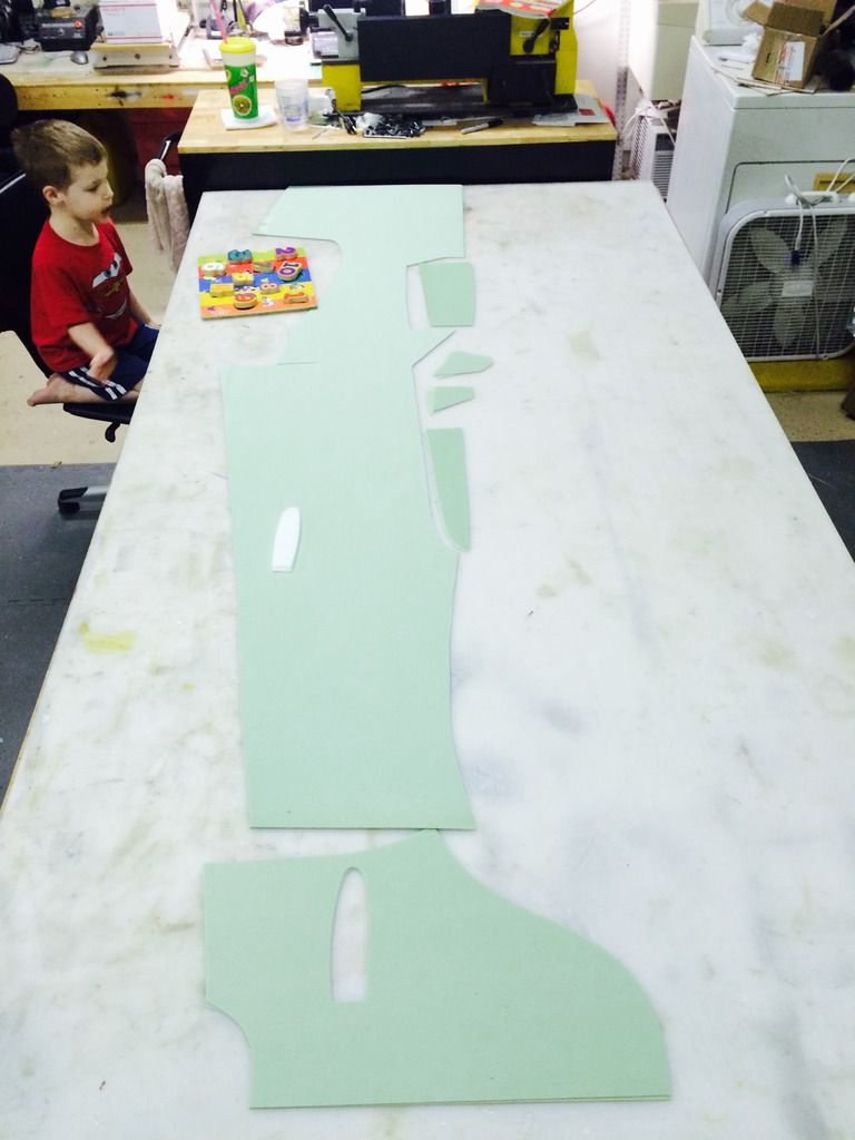
Then the plastic template is used to cut the core material. I'll also use it to cut the glass and carbon fiber layers as well.

This was then removed and transferred to a thin plastic.

Then the plastic template is used to cut the core material. I'll also use it to cut the glass and carbon fiber layers as well.
 05-17-2015, 03:19 PM
#365
Join Date: Jul 2012
Location: Missouri
Posts: 1,127
Likes: 0
Received 0 Likes
on
0 Posts
Thomas,
What is the core material you are using ? Went looking and the only thing I could find that was green was devinycell .
Also if it's not a trade secret. What will be the layering of the fuse layup ?
And will it be different for the wing layup?
Thanks,
Kevin
Kevin
What is the core material you are using ? Went looking and the only thing I could find that was green was devinycell .
Also if it's not a trade secret. What will be the layering of the fuse layup ?
And will it be different for the wing layup?
Thanks,
Kevin
Kevin
05-17-2015, 03:34 PM
#366
Thomas,
What is the core material you are using ? Went looking and the only thing I could find that was green was devinycell .
Also if it's not a trade secret. What will be the layering of the fuse layup ?
And will it be different for the wing layup?
Thanks,
Kevin
Kevin
What is the core material you are using ? Went looking and the only thing I could find that was green was devinycell .
Also if it's not a trade secret. What will be the layering of the fuse layup ?
And will it be different for the wing layup?
Thanks,
Kevin
Kevin
layup- glass, glass,carbon, glass, airex, carbon, glass.. Mostly the same but different for the wing..


 05-17-2015, 05:32 PM
#370
as for the stab, it'll have a hardwood dowel in the LE to set the incidence and the retention system will utilize a countersunk 4-40 bolt drilled through the hardwood block and stab tube. Then in order to remove the stabs, you just remove one bolt and they both come off. No need to remove the other bolt.
One thing that hit me about .2 seconds after tightening the last bolt on the last mold when joining them yesterday is i forgot to install the balsa block for the hardwood antirotation pin. OOPS! Oh well, its not to big of a deal, i can just cut a hole in the root and put one in through that. It is a prototype afterall. Lol
Last edited by invertmast; 05-17-2015 at 05:35 PM.
05-18-2015, 09:30 PM
#371
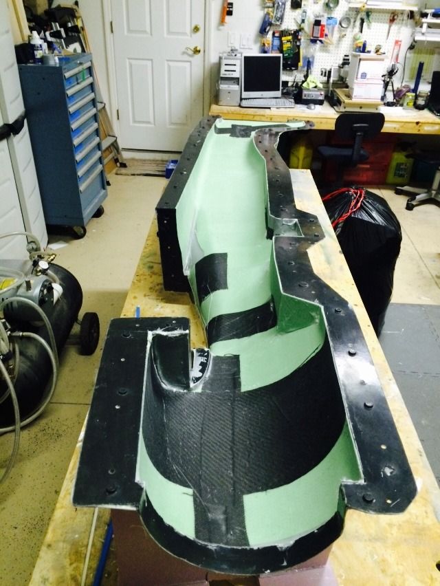
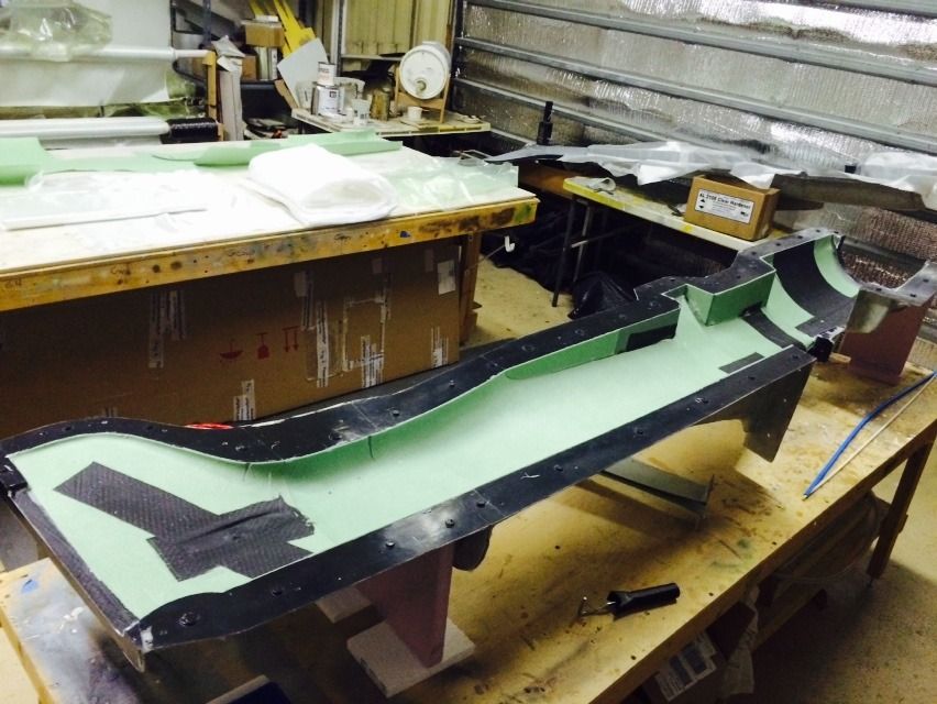
I got a late start, but i got started...
First up was taping off the flanges of the fuse mold and then it was sprayed with primer.
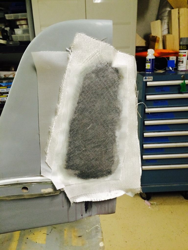
The first layer of glass was then put in and allowed to gell over.

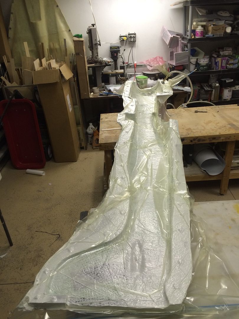
While i was doing the initial layer in the big molds, i did the lower wing fillets and through those in a vacuum bag.
While that initial layer was curing, i had lunch and cut all the glass and carbon fiber layers for the big parts
I them did the layup to the left fuse half and stuck it in a vacuum bag to cure.
I would have done the other side, but it was 11pm by the time i got done, so ill do it tomorrow.
I also pulled the windscreen from the mold. It came out fairly well, the next one i have an idea on how to make it perfect.
First up was taping off the flanges of the fuse mold and then it was sprayed with primer.


The first layer of glass was then put in and allowed to gell over.

While i was doing the initial layer in the big molds, i did the lower wing fillets and through those in a vacuum bag.

While that initial layer was curing, i had lunch and cut all the glass and carbon fiber layers for the big parts

I them did the layup to the left fuse half and stuck it in a vacuum bag to cure.

I would have done the other side, but it was 11pm by the time i got done, so ill do it tomorrow.
I also pulled the windscreen from the mold. It came out fairly well, the next one i have an idea on how to make it perfect.
 05-18-2015, 09:36 PM
#372

Lovely scale details !!!!
Now I start to work with vacoom infusion , the method is perfect for our RC stuff !
What tipe resine you use for the molds ?
Now I start to work with vacoom infusion , the method is perfect for our RC stuff !
What tipe resine you use for the molds ?
Last edited by fokke; 05-18-2015 at 09:38 PM.
05-18-2015, 10:05 PM
#373
Im using Axson's 2108 laminating resin. I also have some Adtech 820 resin as well. The adtech 820 is better suited for infusion.
05-18-2015, 11:46 PM
#374
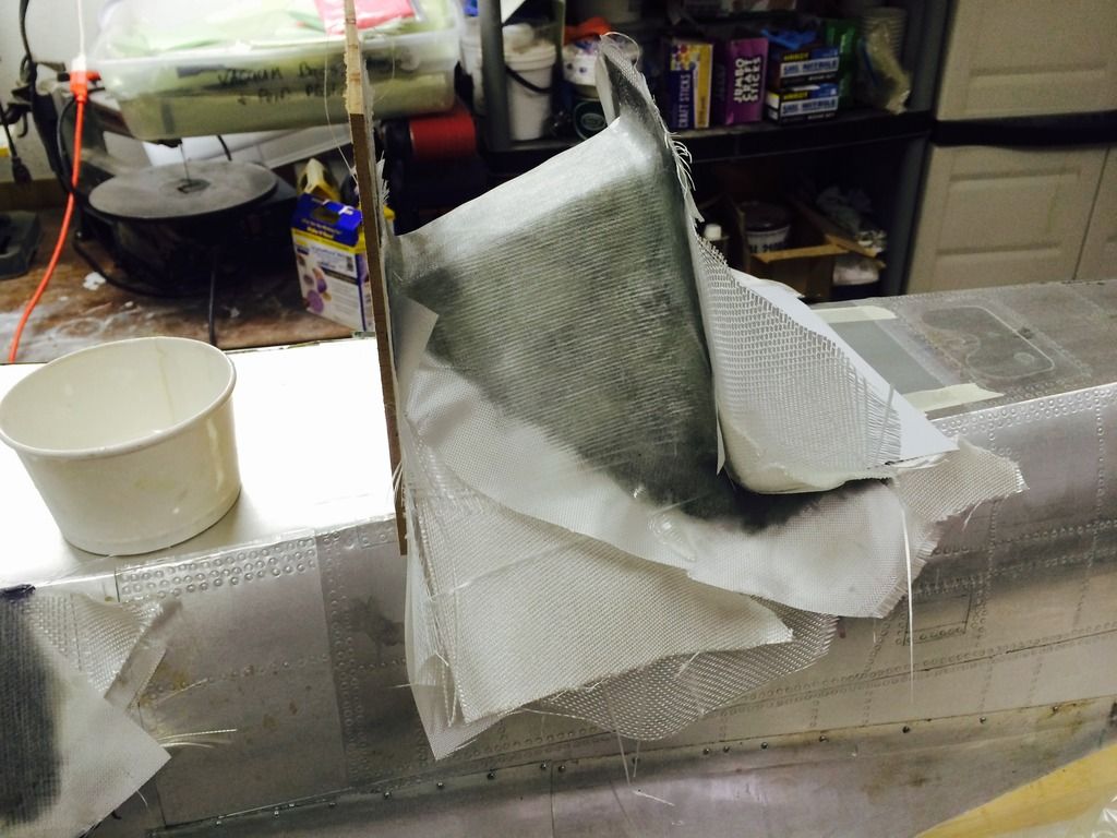
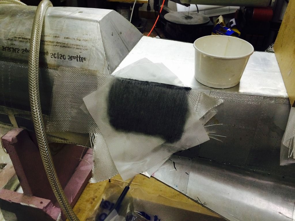
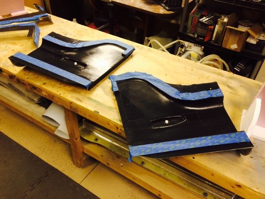
A few hours have passed, so it was time to pull the vacuum bag off and trim everything. To trim i use a Very sharp wood workers file and slowly worky way around. The only real difficult areas are where there is carbon, otherwise if you catch it at just the right time, its all pretty easy to trim.
I then bolted on the lower wing fairing piece. Tomorrow when i do the other fuse side, ill attach this with some cloth and carbon tow.
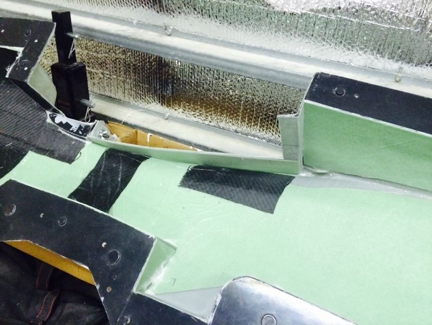


I then bolted on the lower wing fairing piece. Tomorrow when i do the other fuse side, ill attach this with some cloth and carbon tow.

