


Pica 1/5 Scale Mustang Build 2015
 01-03-2021, 07:18 PM
#126

Thread Starter
Yes it is a carbon rod for the flaps.
I'm putting in build log progress on adding features to the wing before I glass it. I put in the shell ejectors. I also wanted to be able to remove the Hangar 9 drop tanks I bought so I had to figure out how to attach them. I may or may not fly with them. I couldn't find any fore aft location dimensions on the internet. A fellow modeler who had a kit gave me dimensions for a 1/5 scale kit relative to the leading edge. Pylon 40 mm back and tank forward of the edge 67 mm. I'll adjust height, and level tank when I drill attachment holes. The issue here is how to attach and be able to remove the tank. I needed to secure them if I flew with them. I made a blade and pocket in the pylon which is just a vacuum formed ABS part.
I used 1/16 G10 to make a blade that would fit the tank to the pylon.

I made a pocket and glued it to a base that fit inside the ther****rm pylon that came with the Pica kit.
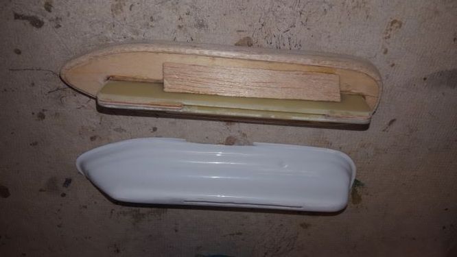
The blades locked in place and slid into the pocket.

I filled the void with lightweight epoxy putty.

This fitment shows where I will drill and tap screws.

The excess balsa was shaved and fitted to the wing at a location 40 mm back from the leading edge.

I epoxied the pylons onto the wing.

I checked the fitment. I'll have to drill holes and level the tanks out relative to the wing.

I smoothed out the gap between the pylon and the wing. I wish Pica curved it to match the airfoil.

I'm putting in build log progress on adding features to the wing before I glass it. I put in the shell ejectors. I also wanted to be able to remove the Hangar 9 drop tanks I bought so I had to figure out how to attach them. I may or may not fly with them. I couldn't find any fore aft location dimensions on the internet. A fellow modeler who had a kit gave me dimensions for a 1/5 scale kit relative to the leading edge. Pylon 40 mm back and tank forward of the edge 67 mm. I'll adjust height, and level tank when I drill attachment holes. The issue here is how to attach and be able to remove the tank. I needed to secure them if I flew with them. I made a blade and pocket in the pylon which is just a vacuum formed ABS part.
I used 1/16 G10 to make a blade that would fit the tank to the pylon.
I made a pocket and glued it to a base that fit inside the ther****rm pylon that came with the Pica kit.
The blades locked in place and slid into the pocket.
I filled the void with lightweight epoxy putty.
This fitment shows where I will drill and tap screws.
The excess balsa was shaved and fitted to the wing at a location 40 mm back from the leading edge.
I epoxied the pylons onto the wing.
I checked the fitment. I'll have to drill holes and level the tanks out relative to the wing.
I smoothed out the gap between the pylon and the wing. I wish Pica curved it to match the airfoil.

The following users liked this post:
PREDHEAD (01-04-2021)
 01-14-2021, 02:28 PM
#128
Thread Starter
The following users liked this post:
PREDHEAD (01-17-2021)
01-14-2021, 02:56 PM
#129
Thread Starter
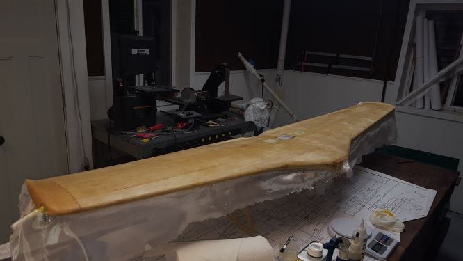
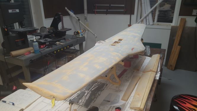
I kept track of the weight increase as I applied the .73 oz. / sq. yd fiberglass. Always curious of the weight gain of finishes.
The estimate of area excludes the ailerons and flaps and is about 2505 sq. in.
Same procedure on both sides; fiberglass then sand edges, second coat then prime and sand all the primer off.
Spot fill and then make it smooth as a baby's butt!
g oz.
Start 2670 g 94.18 oz
After 1st Bottom Resin 2780 g 98.06 oz
After 1st Top Sanded 2915 g 102.82 oz
After 2nd Bottom Resin Sanded 2925 g 103.17 oz
After 2nd Top Resin Sanded 2935 g 103.53 oz
After primer/fill/sanding 2941 g 103.74 o
oz. oz / sq. in.
Increase 9.56 0.003816
01-18-2021, 09:36 AM
#131
Thread Starter
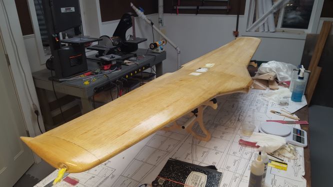
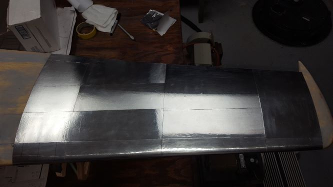
I'm counting about 54 panels between the top and bottom wing surfaces. I'm working about 4 hours at a time and have about 13 done.
After a lot of internet research, the proud panel lines for cutting out the panel shapes were not consistent. There were slight differences on each panel line drawing. My pictures of the full size at my local airport were incomplete so I just made a best judgement.
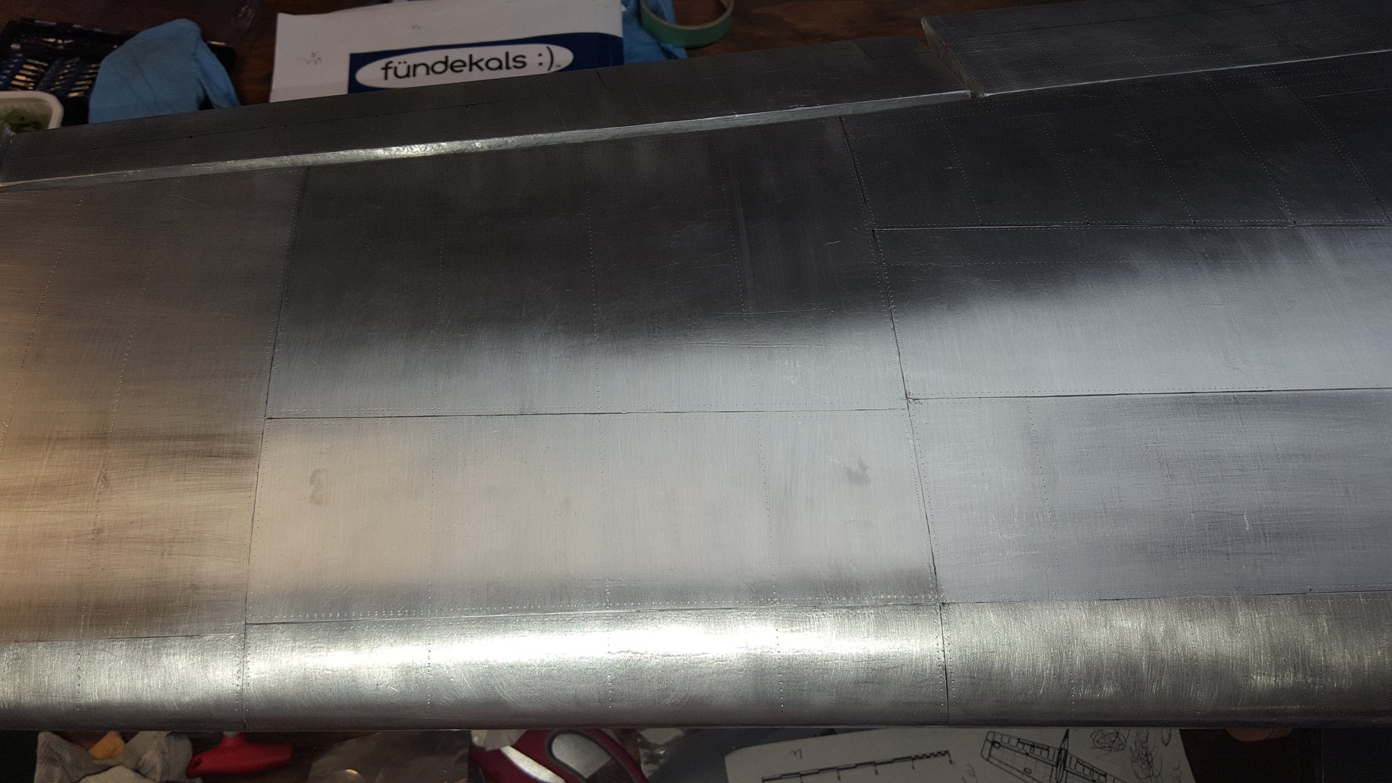
This is a tedious job, but I'm not going to race through it. So far my surface prep seems good. The only blemishes I get seem to be from the foil itself which I know will sand out. I'm not getting any "orange peel" looks so far like I did in spots on the fuselage. I'm guessing a scotch pad treatment will work good enough. We'll soon see.
The first foil panels wrap around the leading edge. The wing tips are the toughest to do. These compound surfaces always wrinkle. Some experts can stretch this stuff a little. Unfortunately, I'm no expert. Perhaps my second plane will be better. It does take some experience to work with foil but you gain it quickly.


After a lot of internet research, the proud panel lines for cutting out the panel shapes were not consistent. There were slight differences on each panel line drawing. My pictures of the full size at my local airport were incomplete so I just made a best judgement.
This is a tedious job, but I'm not going to race through it. So far my surface prep seems good. The only blemishes I get seem to be from the foil itself which I know will sand out. I'm not getting any "orange peel" looks so far like I did in spots on the fuselage. I'm guessing a scotch pad treatment will work good enough. We'll soon see.
The first foil panels wrap around the leading edge. The wing tips are the toughest to do. These compound surfaces always wrinkle. Some experts can stretch this stuff a little. Unfortunately, I'm no expert. Perhaps my second plane will be better. It does take some experience to work with foil but you gain it quickly.
The following 3 users liked this post by szempruw:
01-28-2021, 08:28 AM
#132
Thread Starter
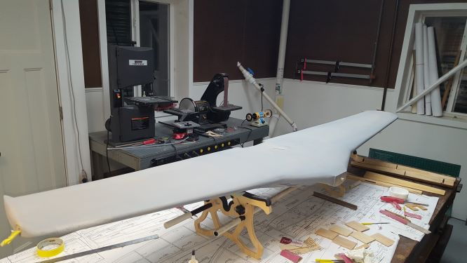
I just have a few small parts to finish. The gear covers are kind of fun to see the concave shape stick well. The scuffing of the panels will be next to get that brushed aluminum effect. Some panels will be stroked 90 degrees as taught by the experts. I still have trouble with compound areas. No matter what I do, I get wrinkles. The wing tips were the worst. They sanded out good enough, but I'd rather avoid.
The final weight for finishing this large surface area with the foil was 3153 g. I started with 2670 g. For the surface area with a better estimate of 2211 sq. in. these are my numbers.
.73 oz. glass 1.245 ozs 7.3%
Resin/ sanded primer 8.31 ozs 48.8%
Flite Metal 7.48 ozs 43.9%.
My total weight gain was 17 ozs. Considering I've found painted models on the forums that increased their total plane weight to about 40 ozs. I'm estimating a total gain of about 29.75 ozs. (Fuselage was done using .53 z glass) I don't think that's too bad. I'm still nervous about my final weight after all the pseudo scale additions I made. We'll soon see. Especially if I have to add more weight in the nose to CG balance.
BTW, it was just over 23 days chronologically since I started fiber glassing. I'd say I worked on this 3-4 hours a day. I didn't push it too hard. i'm sure someone could do it faster. After all, It is a hobby.


.
The final weight for finishing this large surface area with the foil was 3153 g. I started with 2670 g. For the surface area with a better estimate of 2211 sq. in. these are my numbers.
.73 oz. glass 1.245 ozs 7.3%
Resin/ sanded primer 8.31 ozs 48.8%
Flite Metal 7.48 ozs 43.9%.
My total weight gain was 17 ozs. Considering I've found painted models on the forums that increased their total plane weight to about 40 ozs. I'm estimating a total gain of about 29.75 ozs. (Fuselage was done using .53 z glass) I don't think that's too bad. I'm still nervous about my final weight after all the pseudo scale additions I made. We'll soon see. Especially if I have to add more weight in the nose to CG balance.
BTW, it was just over 23 days chronologically since I started fiber glassing. I'd say I worked on this 3-4 hours a day. I didn't push it too hard. i'm sure someone could do it faster. After all, It is a hobby.
.
Last edited by szempruw; 01-28-2021 at 08:36 AM.

 02-10-2021, 07:58 AM
#134
Thread Starter
I'll spend the day adding / tracing minor wing details, I traced the major panels with a black ballpoint pen. I added a bunch of rivet lines but it's driving me crazy to over do it per my guide. I'll look for some minor details to trace. After today, I'll call the wing done and ready to prep for painting. It looks like the time for final assembly is getting near.
I still have to run the motor o break it in when it warms up a bit in early Spring.


I still have to run the motor o break it in when it warms up a bit in early Spring.
03-02-2021, 06:55 PM
#136
Thread Starter
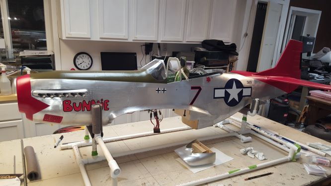
When your friend who has a spray booth offers to paint your plane, you take him up on it. It was nice to see some color on it after staring at aluminum. I used KlasKote epoxy satin. We added a flattener, but the gloss still came through. I'll test some compound to try and matte the finish more.
The assembly was started with the landing gear. The rivet and panel line detail came through under the paint.


Clearly the anti-glare is not anti-glare.


I NEED THAAT LANDING LIGHT FROM Prekin. Hasn't arrived yet.

The assembly was started with the landing gear. The rivet and panel line detail came through under the paint.
Clearly the anti-glare is not anti-glare.
I NEED THAAT LANDING LIGHT FROM Prekin. Hasn't arrived yet.
Last edited by szempruw; 03-02-2021 at 07:00 PM.
The following users liked this post:
PREDHEAD (03-03-2021)


The following users liked this post:
PREDHEAD (03-07-2021)
03-21-2021, 07:41 AM
#140
Thread Starter
I'm getting close to my final posting of this build. I have a few more details and perhaps end this log with a summary of flying it
I need to add an access to the needle valve for adjustment of at least the high end. A drilled out exhaust port is in the right location and I'm thinking of flexible shaft. Details yet to be determined. This would bring adjustments out the cowl.
I suspended the plane to test the electronics. Attaching the wing from the bottom seems best to avoid dinging the foil too much. This setup allowed me to get my hands in there and connect the ribbon. I'm not happy with the way I'm forced to route all the wires, but adding the cockpit details and floor really cramped this area up. For new builders, even adding 1/4" space would help a lot. The floor doesn't need to be so far down to be scale like. My pilot and chair sits a little low anyway. I'm going to work on a PVC pipe and field assembly station for the flying field. The goal is to avoid hangar rash as much as possible.

The electronics and servos needed a little adjustment. But gear, flaps and controls worked out ok.
At this point I took some nearly final pictures before I weighed the plane for a CG check. The good news s that the plane looked good. The bad news is that it came in a little tail heavy. I was hoping that with the batteries far forward, that would be enough. It wasn't. Other Pica kit forum builders said the plane flew well at 29 lbs. With all the semi-scale detail I added, I'm at 29.3 lbs. SHE NEEDS TO GO ON A DIET! The real problem is I am tail heavy by about 35mm or 1.4 in. and too tail heavy. There are some options of moving things around. But the key goal will be to make the tail lighter. It will be difficult, but some scale features may have to go. We'll see, but the the message is clear. Build the tail as light as possible. It's easier to add tail weight later. The tail wheel alone adds a lot of bad weight. I tried to make it light in the first place but it wasn't enough. A tail wheel replacement would be a quick start. Canopy weight will be looked at too. I'm going to goal for removing 4 ounces from the back end.


The little "+ sign" on the side of the fuselage's serial ID is fairly close to my calculated and target CG location. A 10% Static Margin has the CG at 8.023 in. from the "flat" of the front wing. I'm going to double check my numbers. Note: My target location is further aft of the plan's CG. Other Pica kit builders noted it was too far forward. I corresponded with the designer, Jon Tanger and he told me how they picked the CG. They just went for 25% of the chord and after a test flight adjusted from there and made "a little" nose heavy for beginners. However, I sure don't want the plane too tail heavy. It's interesting that the calculations and static margins of 5%-15% offers a wide range of 1.66 in. for choosing the CG location.

At least for now, the intense building part is over and I'm down to adjustments. I'll keep this build log going a bit more at least till I get the maiden flight done. Good luck to all new builders. I've really enjoyed building this kit. Like I've said before, it's like a canvas to upon which to draw!
I need to add an access to the needle valve for adjustment of at least the high end. A drilled out exhaust port is in the right location and I'm thinking of flexible shaft. Details yet to be determined. This would bring adjustments out the cowl.
I suspended the plane to test the electronics. Attaching the wing from the bottom seems best to avoid dinging the foil too much. This setup allowed me to get my hands in there and connect the ribbon. I'm not happy with the way I'm forced to route all the wires, but adding the cockpit details and floor really cramped this area up. For new builders, even adding 1/4" space would help a lot. The floor doesn't need to be so far down to be scale like. My pilot and chair sits a little low anyway. I'm going to work on a PVC pipe and field assembly station for the flying field. The goal is to avoid hangar rash as much as possible.
The electronics and servos needed a little adjustment. But gear, flaps and controls worked out ok.
At this point I took some nearly final pictures before I weighed the plane for a CG check. The good news s that the plane looked good. The bad news is that it came in a little tail heavy. I was hoping that with the batteries far forward, that would be enough. It wasn't. Other Pica kit forum builders said the plane flew well at 29 lbs. With all the semi-scale detail I added, I'm at 29.3 lbs. SHE NEEDS TO GO ON A DIET! The real problem is I am tail heavy by about 35mm or 1.4 in. and too tail heavy. There are some options of moving things around. But the key goal will be to make the tail lighter. It will be difficult, but some scale features may have to go. We'll see, but the the message is clear. Build the tail as light as possible. It's easier to add tail weight later. The tail wheel alone adds a lot of bad weight. I tried to make it light in the first place but it wasn't enough. A tail wheel replacement would be a quick start. Canopy weight will be looked at too. I'm going to goal for removing 4 ounces from the back end.
The little "+ sign" on the side of the fuselage's serial ID is fairly close to my calculated and target CG location. A 10% Static Margin has the CG at 8.023 in. from the "flat" of the front wing. I'm going to double check my numbers. Note: My target location is further aft of the plan's CG. Other Pica kit builders noted it was too far forward. I corresponded with the designer, Jon Tanger and he told me how they picked the CG. They just went for 25% of the chord and after a test flight adjusted from there and made "a little" nose heavy for beginners. However, I sure don't want the plane too tail heavy. It's interesting that the calculations and static margins of 5%-15% offers a wide range of 1.66 in. for choosing the CG location.
At least for now, the intense building part is over and I'm down to adjustments. I'll keep this build log going a bit more at least till I get the maiden flight done. Good luck to all new builders. I've really enjoyed building this kit. Like I've said before, it's like a canvas to upon which to draw!
The following users liked this post:
PREDHEAD (04-24-2021)
05-04-2021, 01:19 PM
#141

Walter,
Excellent Tuskegee Red Tail P-51 ! ! ! !
For someone who's been out of the hobby your skill set is par to someone who's been at it for years. Shipping
your polishing and oxidation retarder tomorrow. Thanks for the spec comparison to paint.
It will find its way to our new website. Glad to see actual data 7.48 oz. (40% less weight than KlasKote paint).
Excellent Tuskegee Red Tail P-51 ! ! ! !
For someone who's been out of the hobby your skill set is par to someone who's been at it for years. Shipping
your
polishing and oxidation retarder tomorrow. Thanks for the spec comparison to paint.It will find its way to our new website. Glad to see actual data 7.48 oz. (40% less weight than KlasKote paint).
Last edited by Flite-Metal; 05-04-2021 at 01:24 PM.


 06-20-2021, 08:56 AM
#144
Thread Starter
Starting at 29.3 lbs., I identified and removed weight, mostly from the tail end. The Century Jet Tail wheel is about 181 g. I recently found that Spektrum/e-Flite came out with 60cc size gear and the tail wheel was much lighter by about 100 g. Unfortunately the easiest way to install the new wheel meant that the forward action couldn't be implemented.
I used a split platform to get the wheel inside and re-enforced in place to install the wheel. Overall I lose about 60 g which is a lot from the tail.
I estimate that I'm at least 28.75 lbs. now and at least within the CG's Static range of 5-15%. I still have a few more opportunities to cut some weight. If my calculations are correct, I think I'm only 11 mm aft of my target location.
Only $90 and much lighter!

Tough getting fingers in there now.

Splitting the plywood allows placement in the wheel well. After a trial fit, I glued and re-enforced in place.


I used a split platform to get the wheel inside and re-enforced in place to install the wheel. Overall I lose about 60 g which is a lot from the tail.
I estimate that I'm at least 28.75 lbs. now and at least within the CG's Static range of 5-15%. I still have a few more opportunities to cut some weight. If my calculations are correct, I think I'm only 11 mm aft of my target location.
Only $90 and much lighter!
Tough getting fingers in there now.
Splitting the plywood allows placement in the wheel well. After a trial fit, I glued and re-enforced in place.
06-24-2021, 10:35 AM
#145
Thread Starter
My main concern and why I'm writing this is that the CG location is "good enough" to maiden the flight of plane that took a long time to build, and I hate to stall and crash on the first flight.
I can't find much about the CG on the full size aircraft from which to compare.
So I'm throwing this out to the forum to see if anyone has any recent experience with the flight of a Pica P51. One fellow told me he had a 22 lb. airplane with CG set per the plane and it flew apparently well enough. I'm busily removing as much tail weight as possible to achieve a CG target with a Static Margin of 10%. Perhaps more if I can.
I've researched this subject a bit and I looked at how some guys double-checked their Pica P51 CG Location. For the record, I corresponded with the designer of the Pica P51 and here is his response to 2 CG questions:
Any experienced comments will be appreciated. Unknown comments aren't necessary. When I do maiden this plane, the proof will be in the pudding.
Correspondence:I caught on the forums that the location of the CG should be aft of the plan�s location by as much a 2 inches. I did a preliminary calculation and admittedly, I may be doing it wrong. I get a location aft by about 1 1/4 inches. Some planes fly poorly with CG locations in correct location, but tail heavy planes don�t fly at all. The wing is a compound structured wing and I am not yet sure, (I�m researching this) what are the appropriate measurements to be used to declare the intended CG location.
"The only model we had problems with was the 88� Spitfire. At that time we used hand drawn plans, and the CG mark was a stick on decal. Somehow this shifted or was moved by someone at the printer (we never found out how) and the CG location was 2-1/4� too far forward. I do not recall any other issues with the CG on the other models. I did not see any mention of a CG problem in the RCM article you attached."
Do you recall how the CG was determined?
"Generally yes, specifically for the P-51, no. We generally started about 30% of the chord at the root, balance the model with no fuel. Then fill it up and test it. See how it handles. Sometime you get the spot right the first time, others we would play with. Once we get the flight where it feels right, we would then move the CG back a couple % to insure a slightly nose heavy model. As you said, nose heavy fly�s, tail heavy� We also have to deal with modelers who are not ready for the larger scale aircraft. We would encourage a progression through the trainers, sport models, and work your way up to a large scale model. However we had a share who went from trainer to scale. Also, some modelers we not good at drawing an imaginary line where the CG should be. We felt this extra margin of error would only help."
My Conclusion:
What I believe, based on calculations, is that there is a generous CG range of 0.83" based on the Static Margin selected. At 5%, the plane is more Tail Heavy and twitchier and more control responsive. At 15%, it's more Nose Heavy more stable in a glide, but a little less responsive to controls.
I plugged in my measured numbers on two different on-line CG calculators, and they were in agreement. I also deducted the front root chord amount of 11/16" to the "flat" on the front of the wing to have a convenient measuring point.
First, these are the dimensions I input to the software. I changed the choice of the static margin (5%. 10%. 15%) to obtain the CG Location. Note that I used the 2 panel method as opposed to using single panel calculation as done by others. I feel the result is more accurate.

This shows the location of the CG from the "flat" and my target CG location using a static margin of 10%

I made this file to show the 3 static margin locations. Note also that a previous builder, "Flyjets", put an extensive review on this forum and made recommendations for the CG location. His recommendation is pretty close to my target 10% value. He preferred to fly in this manner. At the time, there was controversy about the CG location, but as my correspondence with the designer, Jon Tanger indicated, the CG for the P51 was purposefully put in a location to be "Nose Heavy" for inexperienced pilots.

Again, anyone with experience will be appreciated. Unknown comments aren't necessary. When I do maiden this plane, the proof will be in the pudding.
I can't find much about the CG on the full size aircraft from which to compare.
So I'm throwing this out to the forum to see if anyone has any recent experience with the flight of a Pica P51. One fellow told me he had a 22 lb. airplane with CG set per the plane and it flew apparently well enough. I'm busily removing as much tail weight as possible to achieve a CG target with a Static Margin of 10%. Perhaps more if I can.
I've researched this subject a bit and I looked at how some guys double-checked their Pica P51 CG Location. For the record, I corresponded with the designer of the Pica P51 and here is his response to 2 CG questions:
Any experienced comments will be appreciated. Unknown comments aren't necessary. When I do maiden this plane, the proof will be in the pudding.
Correspondence:I caught on the forums that the location of the CG should be aft of the plan�s location by as much a 2 inches. I did a preliminary calculation and admittedly, I may be doing it wrong. I get a location aft by about 1 1/4 inches. Some planes fly poorly with CG locations in correct location, but tail heavy planes don�t fly at all. The wing is a compound structured wing and I am not yet sure, (I�m researching this) what are the appropriate measurements to be used to declare the intended CG location.
"The only model we had problems with was the 88� Spitfire. At that time we used hand drawn plans, and the CG mark was a stick on decal. Somehow this shifted or was moved by someone at the printer (we never found out how) and the CG location was 2-1/4� too far forward. I do not recall any other issues with the CG on the other models. I did not see any mention of a CG problem in the RCM article you attached."
Do you recall how the CG was determined?
"Generally yes, specifically for the P-51, no. We generally started about 30% of the chord at the root, balance the model with no fuel. Then fill it up and test it. See how it handles. Sometime you get the spot right the first time, others we would play with. Once we get the flight where it feels right, we would then move the CG back a couple % to insure a slightly nose heavy model. As you said, nose heavy fly�s, tail heavy� We also have to deal with modelers who are not ready for the larger scale aircraft. We would encourage a progression through the trainers, sport models, and work your way up to a large scale model. However we had a share who went from trainer to scale. Also, some modelers we not good at drawing an imaginary line where the CG should be. We felt this extra margin of error would only help."
My Conclusion:
What I believe, based on calculations, is that there is a generous CG range of 0.83" based on the Static Margin selected. At 5%, the plane is more Tail Heavy and twitchier and more control responsive. At 15%, it's more Nose Heavy more stable in a glide, but a little less responsive to controls.
I plugged in my measured numbers on two different on-line CG calculators, and they were in agreement. I also deducted the front root chord amount of 11/16" to the "flat" on the front of the wing to have a convenient measuring point.
First, these are the dimensions I input to the software. I changed the choice of the static margin (5%. 10%. 15%) to obtain the CG Location. Note that I used the 2 panel method as opposed to using single panel calculation as done by others. I feel the result is more accurate.
This shows the location of the CG from the "flat" and my target CG location using a static margin of 10%
I made this file to show the 3 static margin locations. Note also that a previous builder, "Flyjets", put an extensive review on this forum and made recommendations for the CG location. His recommendation is pretty close to my target 10% value. He preferred to fly in this manner. At the time, there was controversy about the CG location, but as my correspondence with the designer, Jon Tanger indicated, the CG for the P51 was purposefully put in a location to be "Nose Heavy" for inexperienced pilots.
Again, anyone with experience will be appreciated. Unknown comments aren't necessary. When I do maiden this plane, the proof will be in the pudding.
09-16-2021, 06:08 AM
#146
Thread Starter
This past 9/11/2021 I had the chance to display the nearly completed model. With lot's of effort, I'm down to 29.03 lbs. and at about 7.3% Static Margin or about .33 in. more tail heavy than I would like. I'm going to use a Vanessa Rig to cross check my CG location and verify the amount of weight needed in the front to balance. I can still remove the canopy servo to reduce weight. The moral of the story here is build the tail light as you can! .
Transport and assembly is tough too. I need to find an easier way. One Pica builder recommended a wing tube design change for assembly. It's worth a thought.


Transport and assembly is tough too. I need to find an easier way. One Pica builder recommended a wing tube design change for assembly. It's worth a thought.
The following users liked this post:
PREDHEAD (10-06-2021)
10-11-2021, 07:57 AM
#150
Thread Starter
Hey Predhead, Your plane's looking good. I like to watch the progress of a build. I have a suggestion. Think about setting up a build log on this site. You can post all your pictures and it will be fun to watch your progress all in one spot.
Just sayin' it would be a good idea. If you organize it from the beginning you can show others the whole thing at once and they too can learn of build problems you have over come.
Just sayin' it would be a good idea. If you organize it from the beginning you can show others the whole thing at once and they too can learn of build problems you have over come.