New CARF P-51D Project


 09-23-2021, 09:51 AM
#252
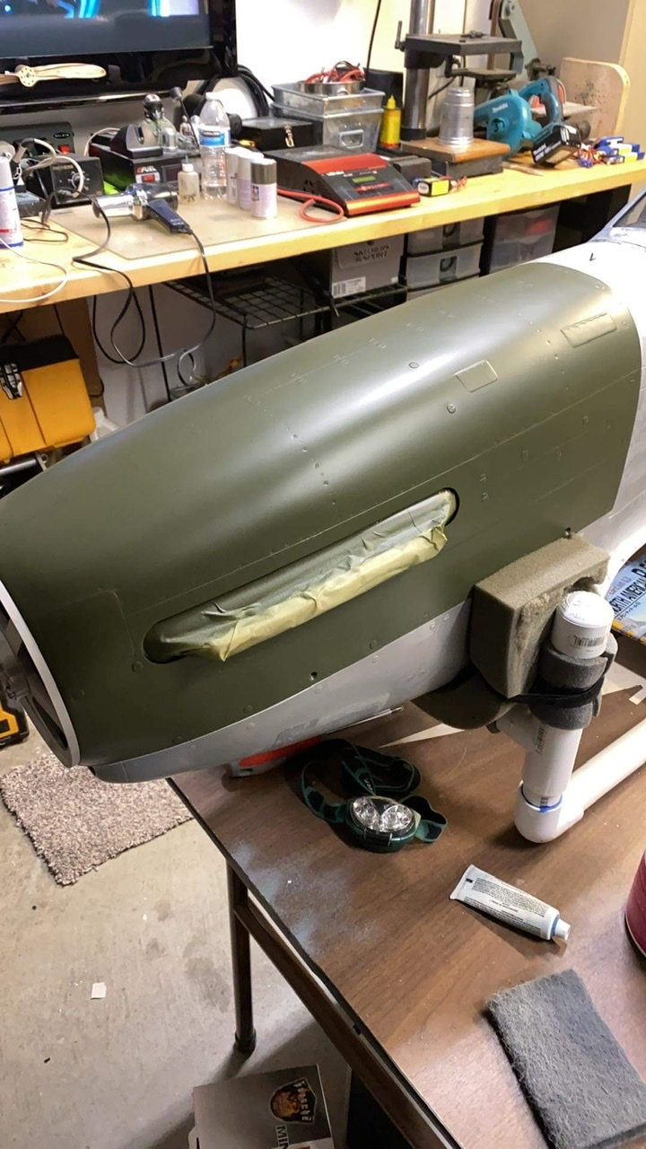
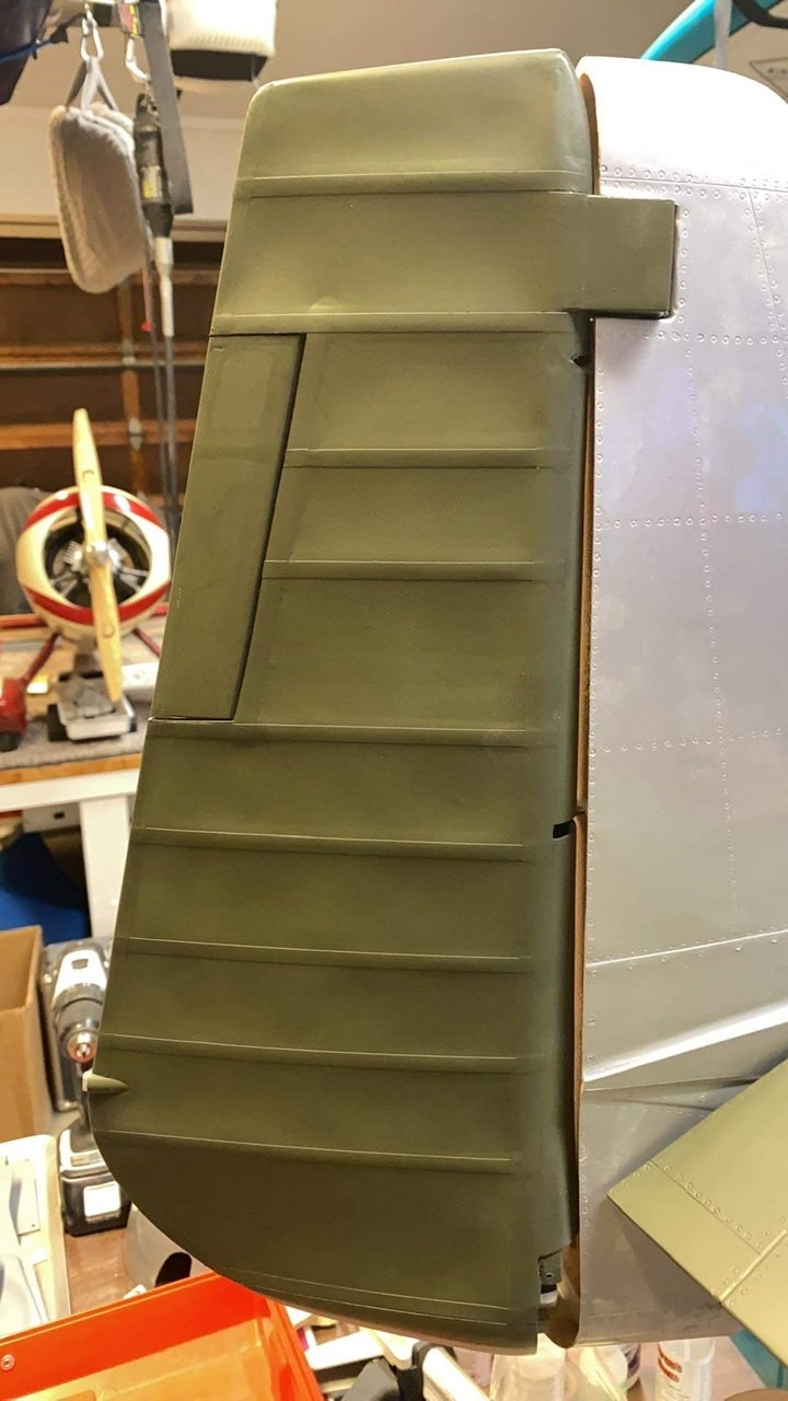
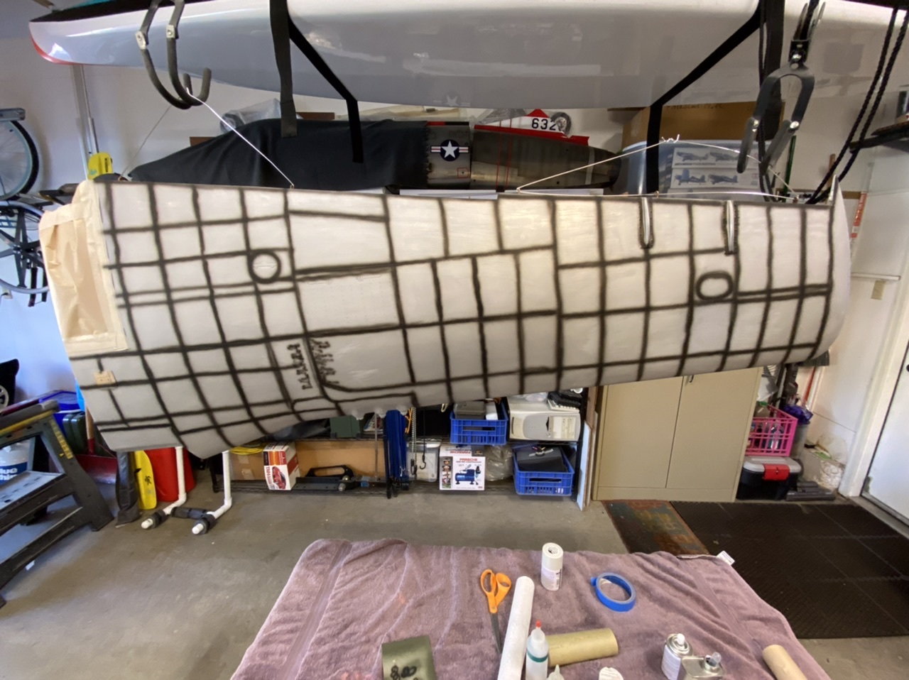
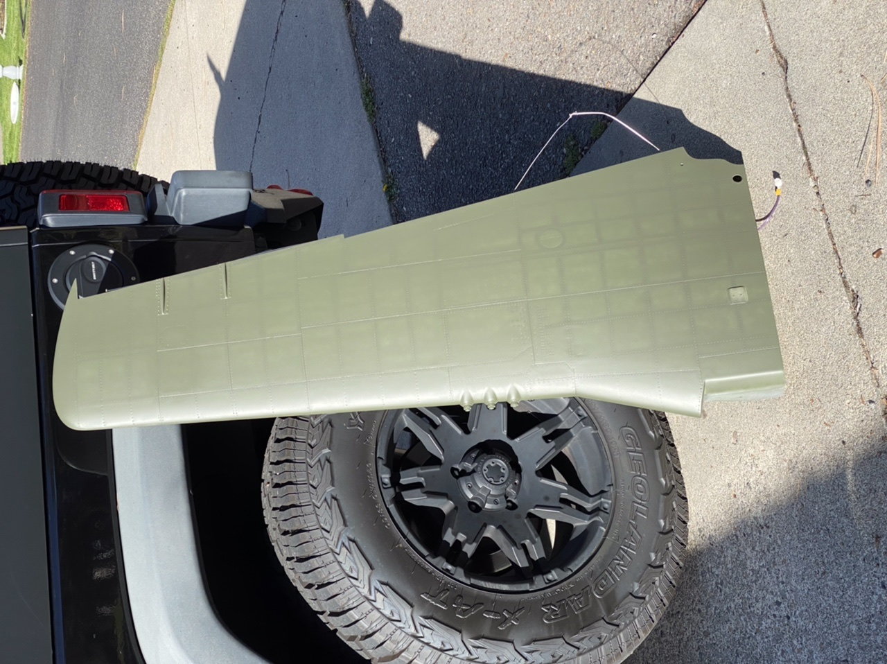
Starting to get some paint on it…
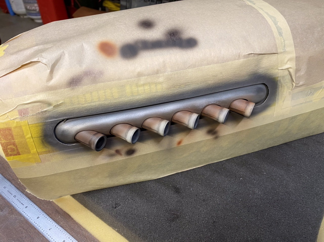
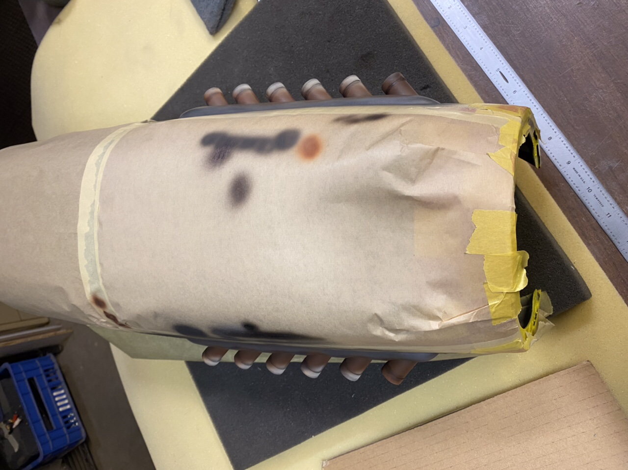
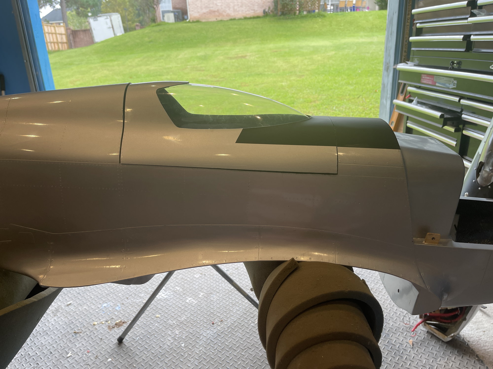
I pre-shaded the panel lines and rivets before spray painting the olive drab to see if it would work. It does and it doesn’t because the spray cans can vary and so can the coverage which if it gets too heavy eliminates the pre-shading effect. The cowl doesn’t show the technique but the stabs do. At least the whole plane will be done this way and it will add some interest to the base layer of paint before I go back and add contrast and weathering.
I pre-shaded the panel lines and rivets before spray painting the olive drab to see if it would work. It does and it doesn’t because the spray cans can vary and so can the coverage which if it gets too heavy eliminates the pre-shading effect. The cowl doesn’t show the technique but the stabs do. At least the whole plane will be done this way and it will add some interest to the base layer of paint before I go back and add contrast and weathering.
 09-29-2021, 12:33 AM
#255
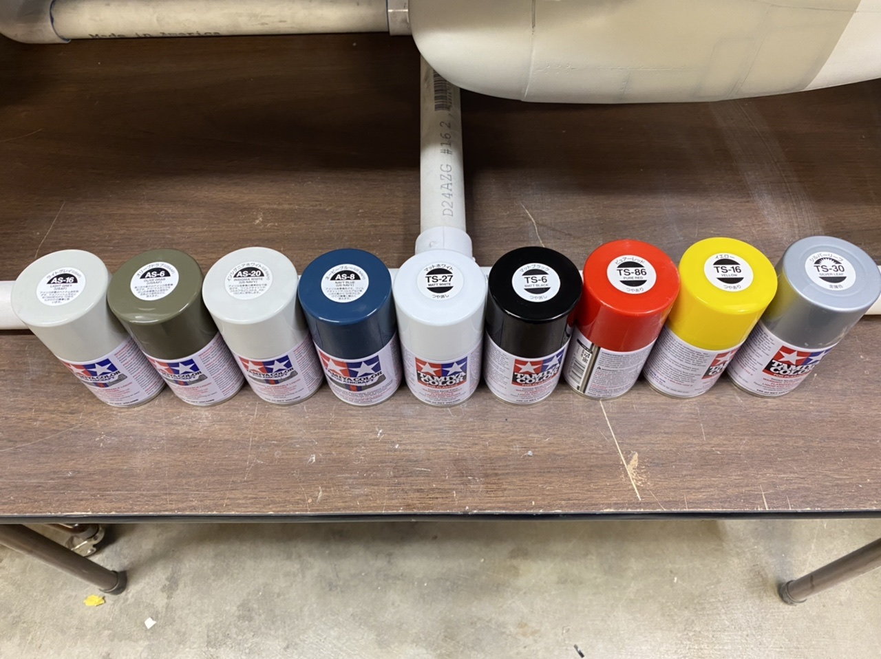
Getting some paint done! Here is a test I’m doing to try preshaping the panel lines and then spraying over with the base color. I’m trying this out with Tamiya lacquer spray cans and so far it’s going ok as a basis to start with. I could leave it or push it with more weathering and contrast but we’ll see. Right now I’m more concerned with just getting the basic scheme done.
The following users liked this post:
Chris Nicastro (10-03-2021)
The following users liked this post:
Chris Nicastro (10-03-2021)
10-03-2021, 10:26 PM
#258
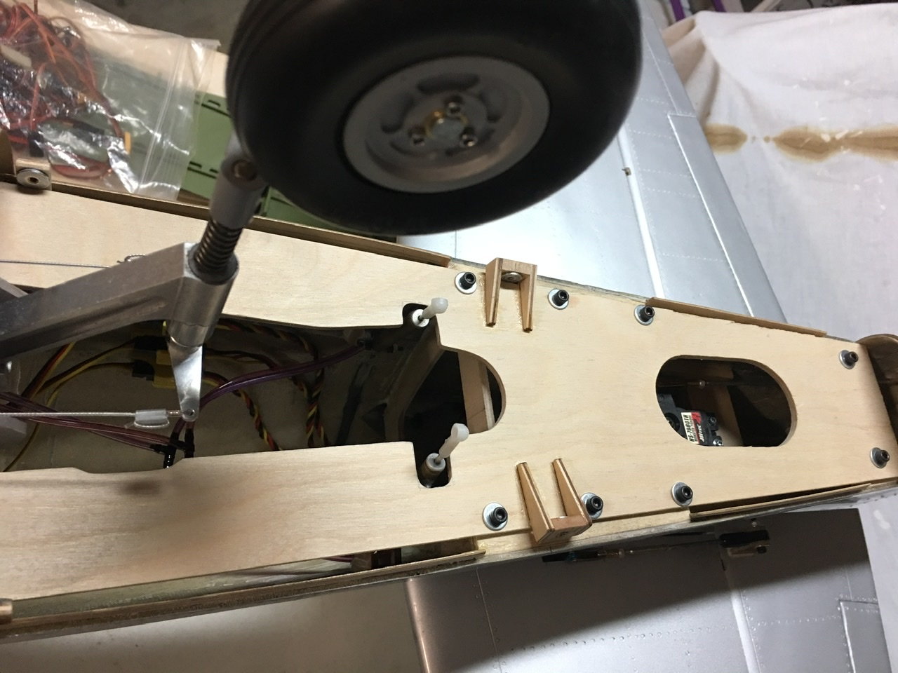
I used 4-40 flat head Allen screws and threaded inserts for hardware.
 10-04-2021, 01:10 AM
#259

My Feedback: (1)
that is super nice. thank you for posting this,
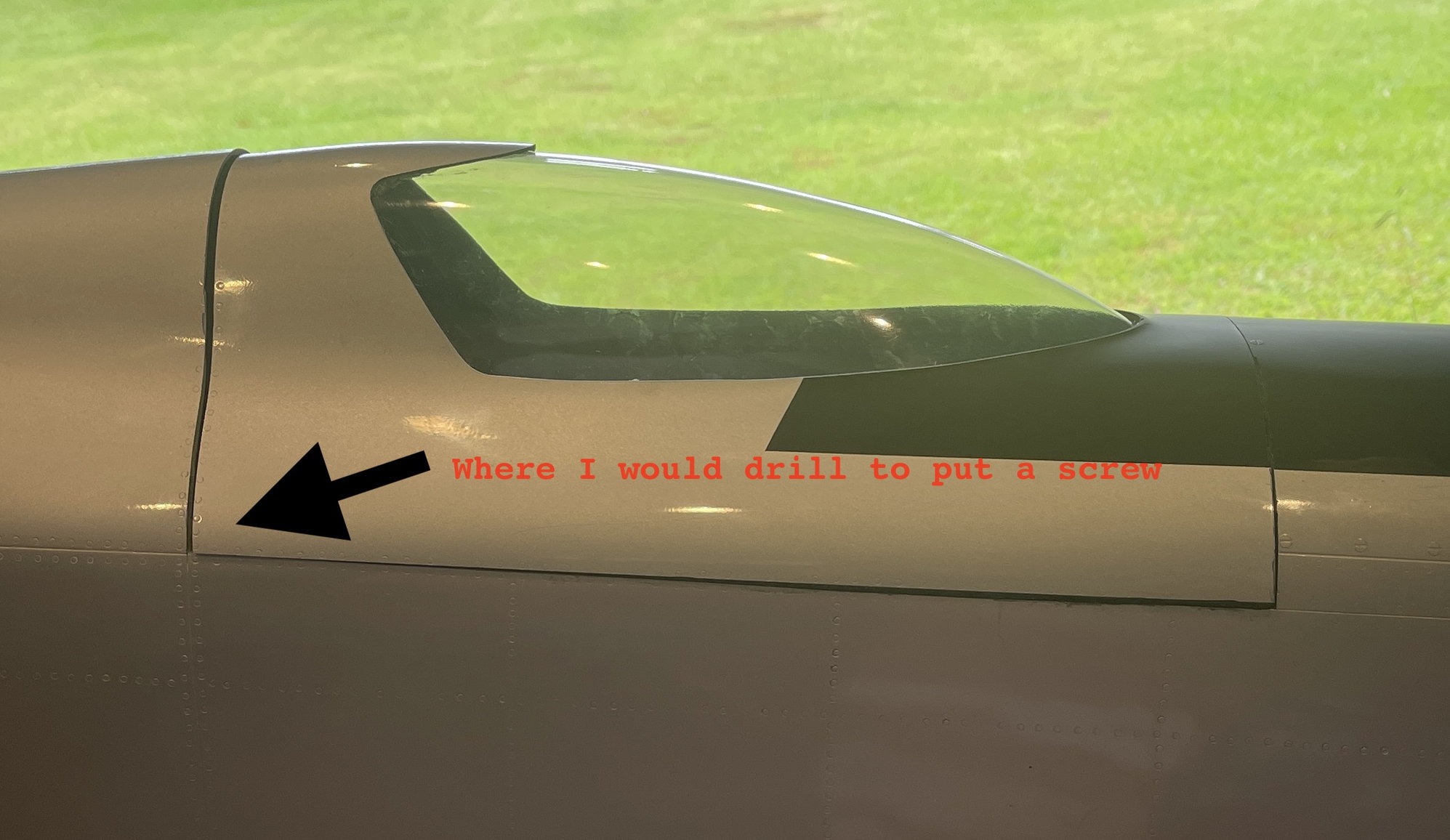
Ok, I am so sorry to ask this, on the composite side, meaning the shell, did you reinforce this in any way? Where the screws go thru the composite material?
reason I am asking,
I have a CARF P51 GG, and i did not like the access thru the wing saddle only.
Mind you, my airplane is nothing scale. It is meant for speed.
this is what I have done so far. I am not done with it.

any advice would be greatly appreciated
sorry to sidereal your wonderful build thread.
Ok, I am so sorry to ask this, on the composite side, meaning the shell, did you reinforce this in any way? Where the screws go thru the composite material?
reason I am asking,
I have a CARF P51 GG, and i did not like the access thru the wing saddle only.
Mind you, my airplane is nothing scale. It is meant for speed.
this is what I have done so far. I am not done with it.
any advice would be greatly appreciated
sorry to sidereal your wonderful build thread.
10-04-2021, 01:48 PM
#260
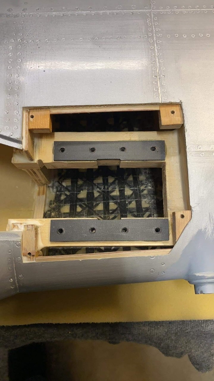
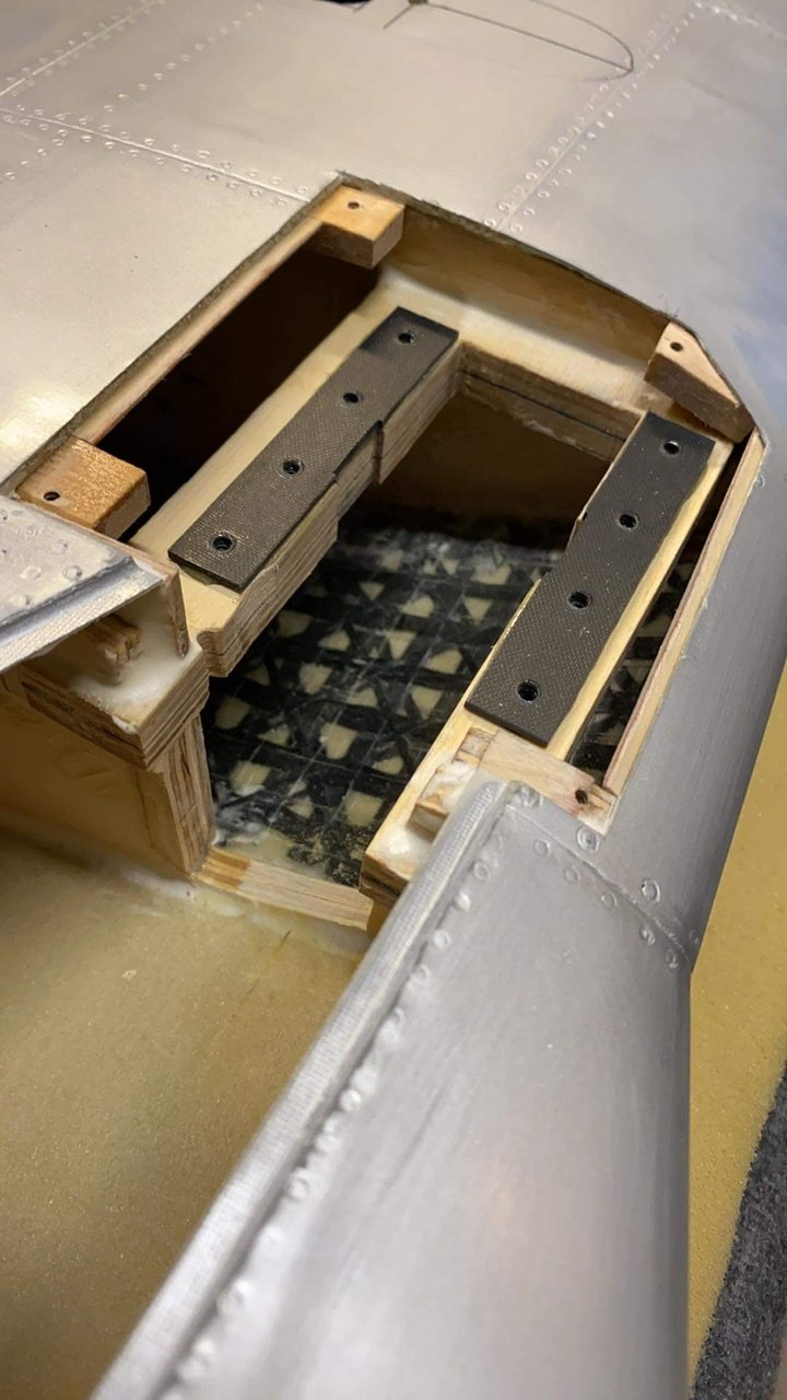
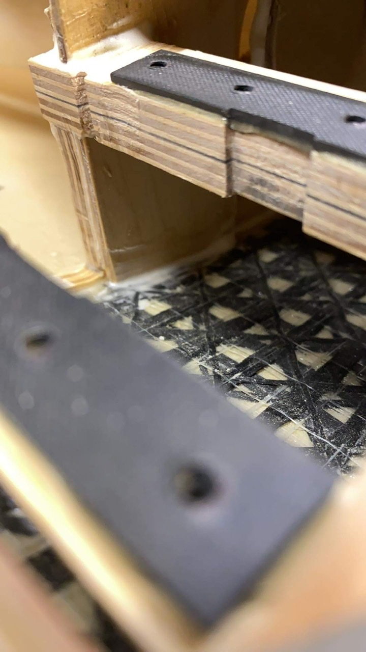
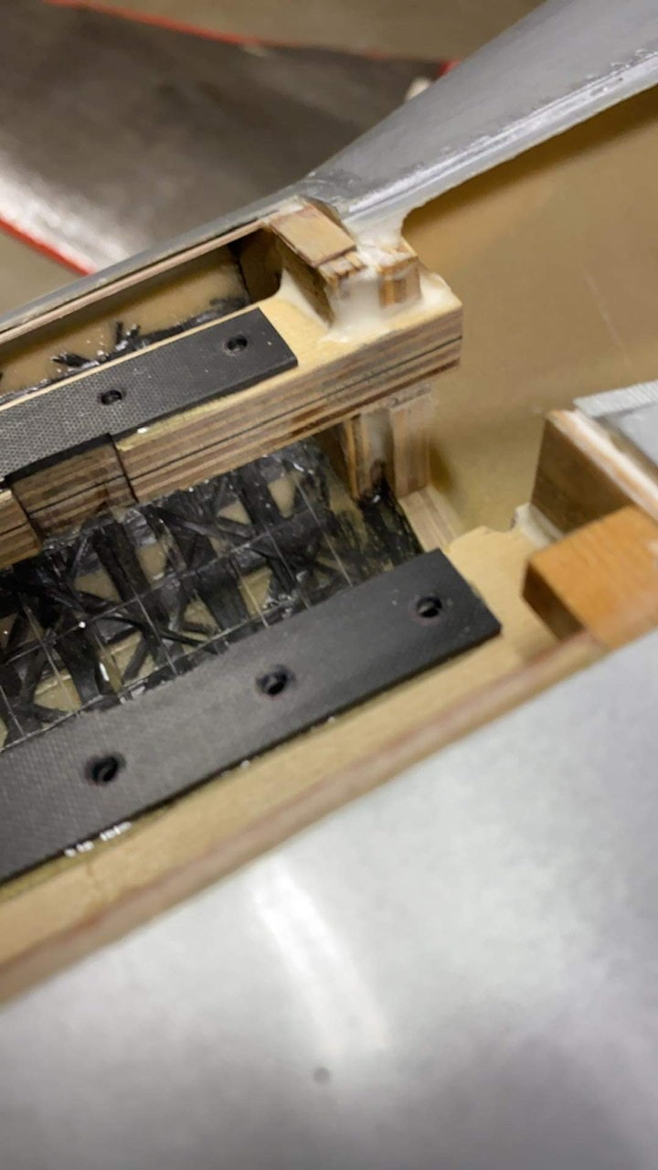
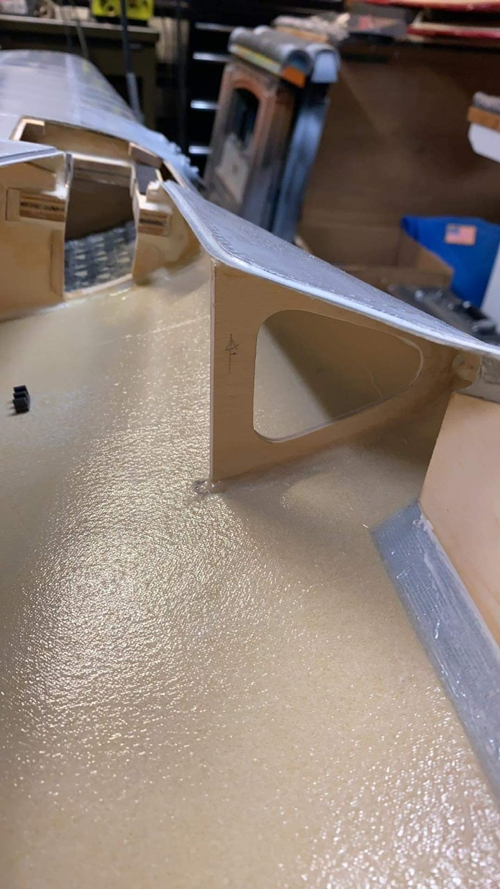
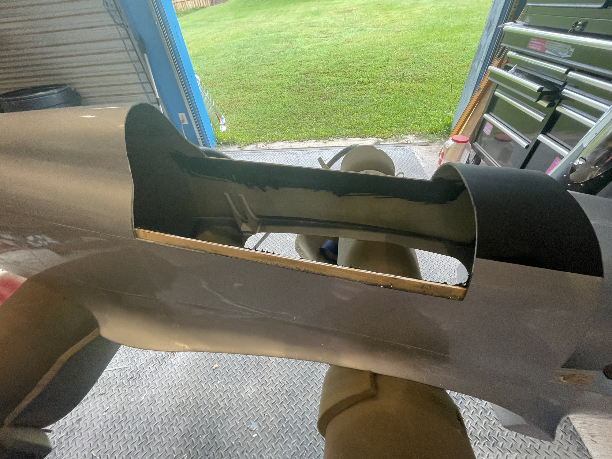
Ok I see what you mean. Yes I removed the foam from the composite layup and then built it back up with plywood before I drilled holes. The size of the wood inserts, let’s call them, depends on you but I make them at least 4x larger than the area of the head of the countersink screw to distribute the load. Also the thickness must be more than the depth of the CS screw head.
I usually locate a screw like a countersink screw about half the diameter of the head away from the edge of something. That puts the center of the screw far enough away from the edge to be safe as a minimum distance, more could be better. So for example; diameter of the screw head = .25 then I add 0.125 so basically the center of the screw would be .25 from the edge of the part. Flat surfaces are preferable to curvy complicated ones. Avoid getting really close to the edges so the composite material doesn’t blow out.
#1 decide where to put the screws, the corners maybe one in the middle if it’s flimsy
#2 decide the size of the plywood or whatever material, carbon fiber, you’re going to use
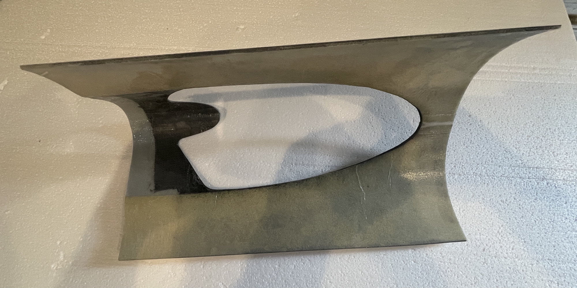
#3 remove the foam from the area to the skin of the hatch and epoxy them in place, use good epoxy for laminating/bonding not finishing, West Systems, Locktite Hysol
#4 hatch taped in place drill your pilot holes
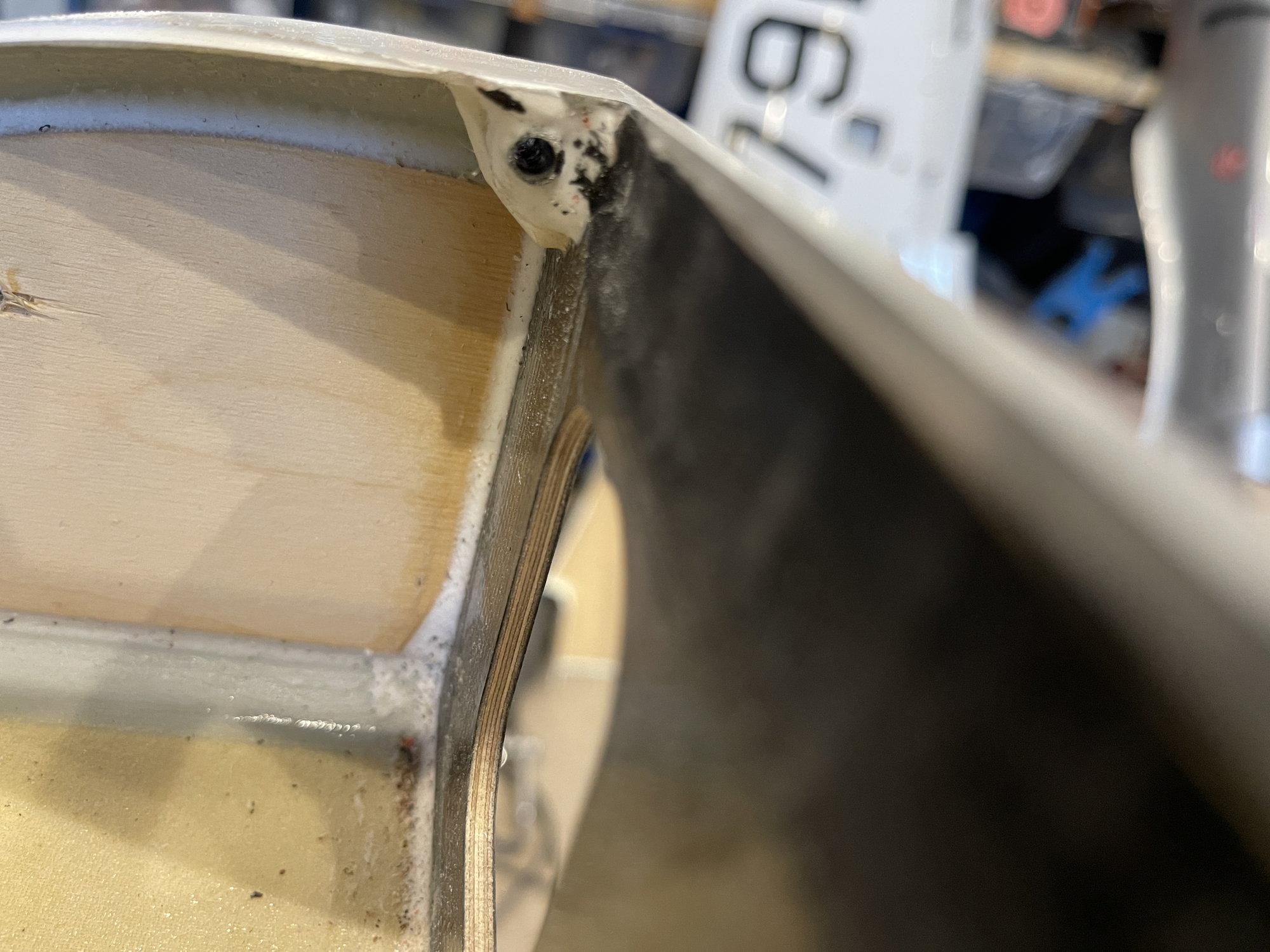
#5 install the threaded inserts in the fuselage, don’t use the flanged hobby grade 4-40 use the machined brass type. In my photo I soldered inserts to washers and glued them in plywood
#6 test the screws before you counter sink the holes so the hatch is located correctly, it’s harder to do later
#7 counter sink the holes and get the depth right so the screw is flush
#8 recheck fit and look
#9 apply thin CA to the counter sink to toughen it up
#10 scuff, clean, and paint the screw heads to match the fuselage color
Try that and see maybe on a test panel and go from there.
I usually locate a screw like a countersink screw about half the diameter of the head away from the edge of something. That puts the center of the screw far enough away from the edge to be safe as a minimum distance, more could be better. So for example; diameter of the screw head = .25 then I add 0.125 so basically the center of the screw would be .25 from the edge of the part. Flat surfaces are preferable to curvy complicated ones. Avoid getting really close to the edges so the composite material doesn’t blow out.
#1 decide where to put the screws, the corners maybe one in the middle if it’s flimsy
#2 decide the size of the plywood or whatever material, carbon fiber, you’re going to use
#3 remove the foam from the area to the skin of the hatch and epoxy them in place, use good epoxy for laminating/bonding not finishing, West Systems, Locktite Hysol
#4 hatch taped in place drill your pilot holes
#5 install the threaded inserts in the fuselage, don’t use the flanged hobby grade 4-40 use the machined brass type. In my photo I soldered inserts to washers and glued them in plywood
#6 test the screws before you counter sink the holes so the hatch is located correctly, it’s harder to do later
#7 counter sink the holes and get the depth right so the screw is flush
#8 recheck fit and look
#9 apply thin CA to the counter sink to toughen it up
#10 scuff, clean, and paint the screw heads to match the fuselage color
Try that and see maybe on a test panel and go from there.
The following users liked this post:
orthobird (10-04-2021)
The following users liked this post:
Chris Nicastro (10-04-2021)
10-11-2021, 06:43 PM
#262
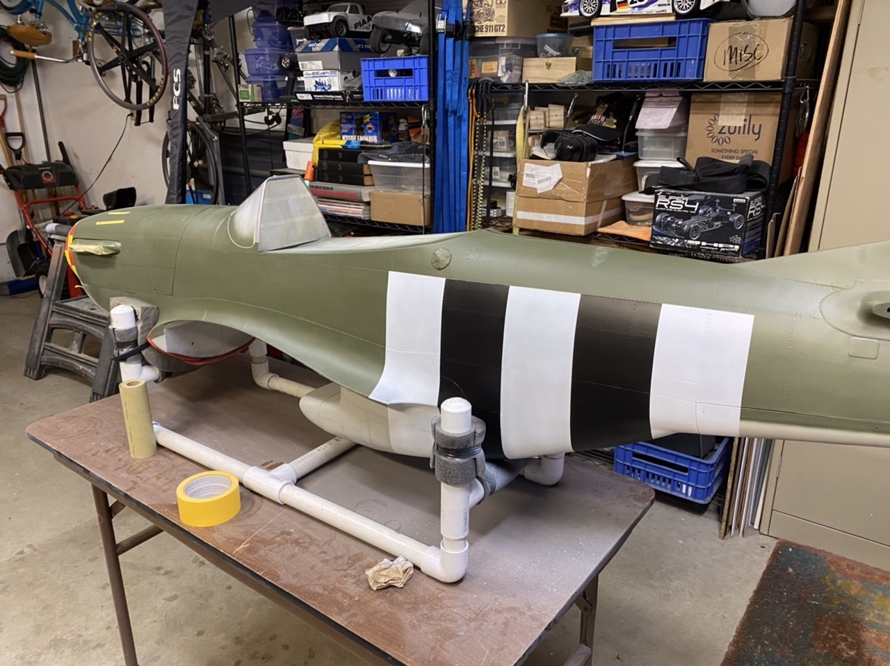
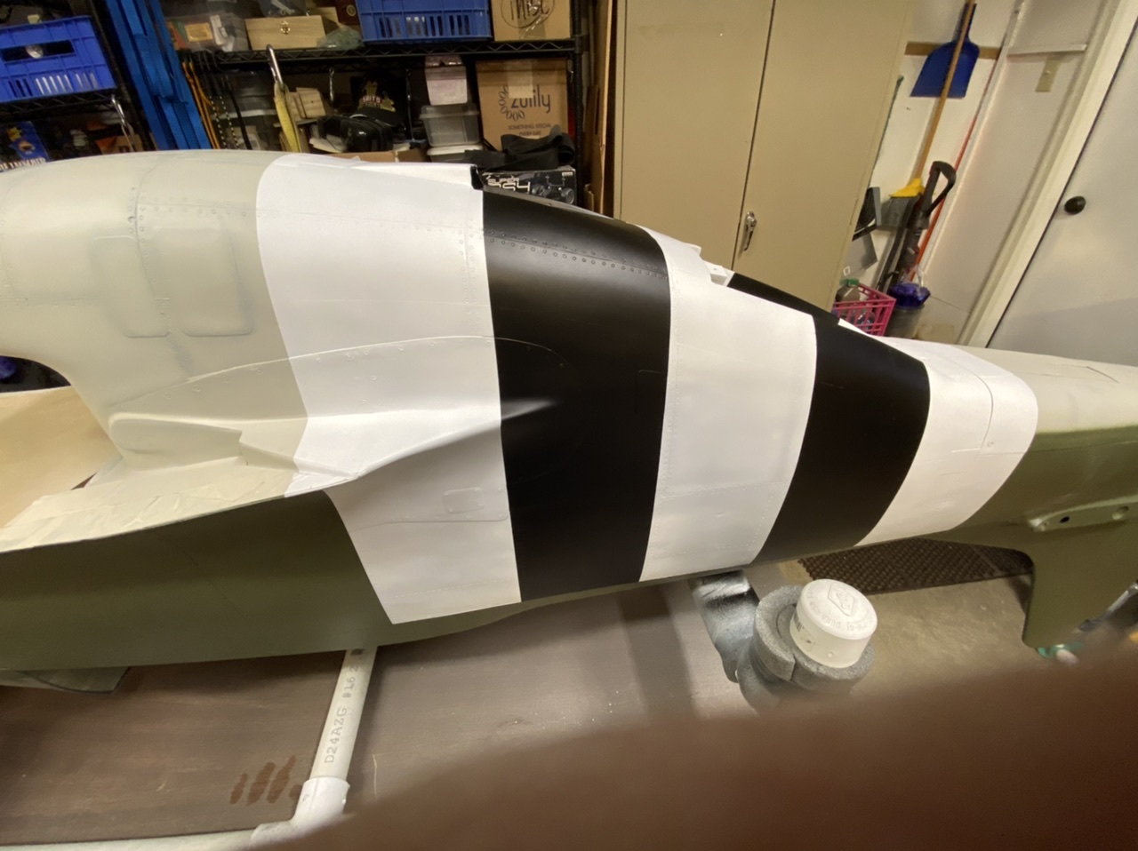
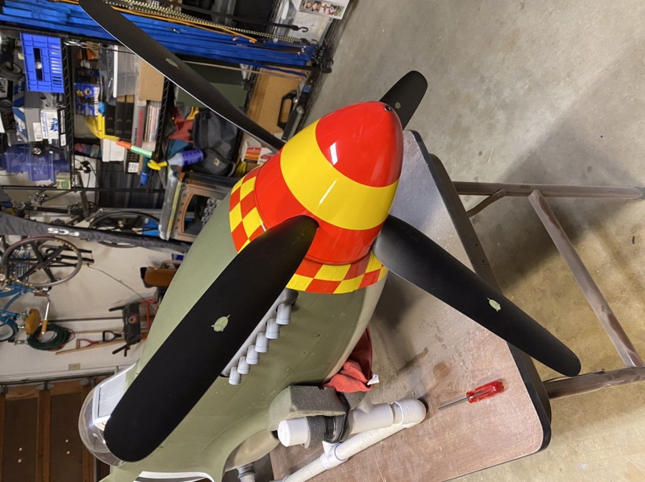
I must hate myself, I decided to paint checkers on the nose. Not just any checkers, Mustang checkers. Did you know pretty much every planes checkers are unique? The Frenesi checkers are not symmetrical either, odd numbered too. Then to complicate things further my masking set came in 1/4 scale not 1/4.4 as ordered so I couldn’t finish it. The checkers are freehand but the mask set is for the all the graphics. Tapered, custom, asymmetrical checkers!!!


The following users liked this post:
Chris Nicastro (10-12-2021)
10-17-2021, 11:48 PM
#265
Making progress…
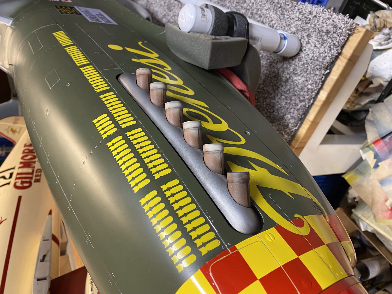
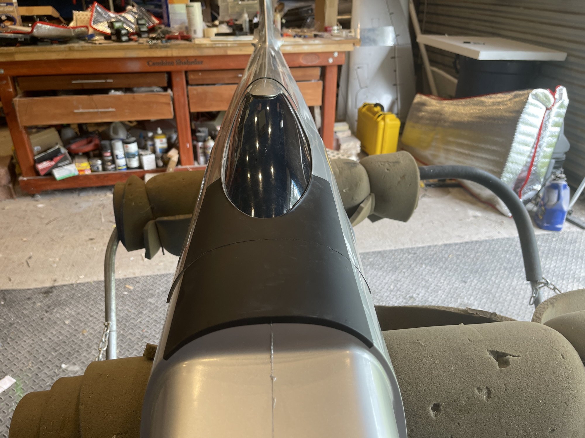
The nose paint is done except the exhaust but that’s next.
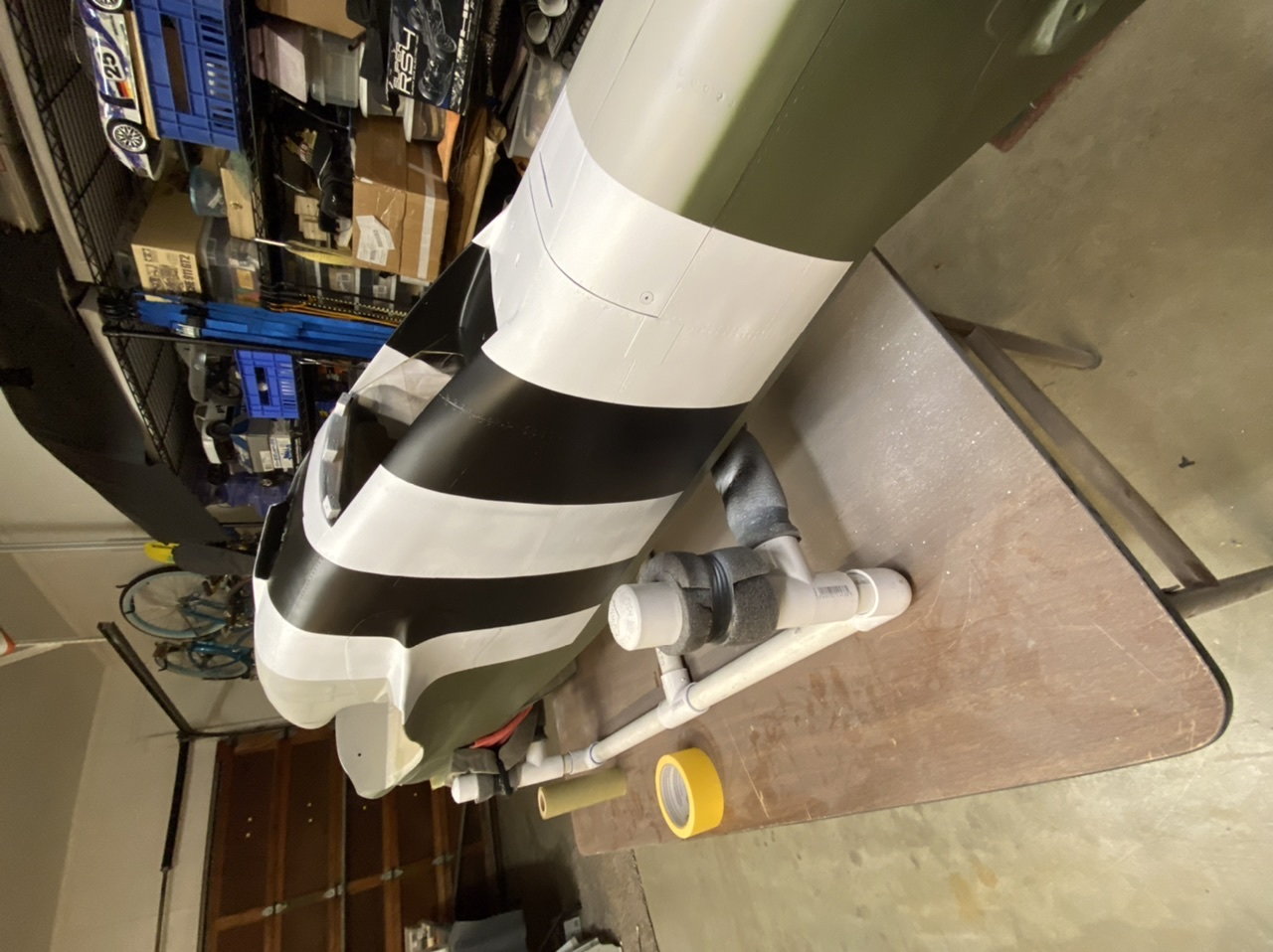
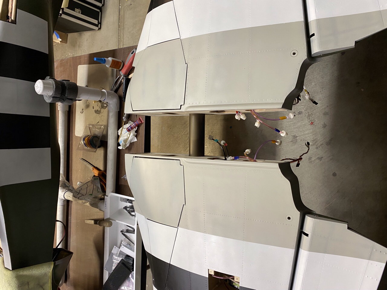
A all the stripes are painted now I’m waiting for the replacement mask set because they sent the wrong scale size.
I’ll be getting the plane assembled and balanced ready to go here very soon!
The nose paint is done except the exhaust but that’s next.
A all the stripes are painted now I’m waiting for the replacement mask set because they sent the wrong scale size.
I’ll be getting the plane assembled and balanced ready to go here very soon!
The following users liked this post:
Chris Nicastro (10-18-2021)
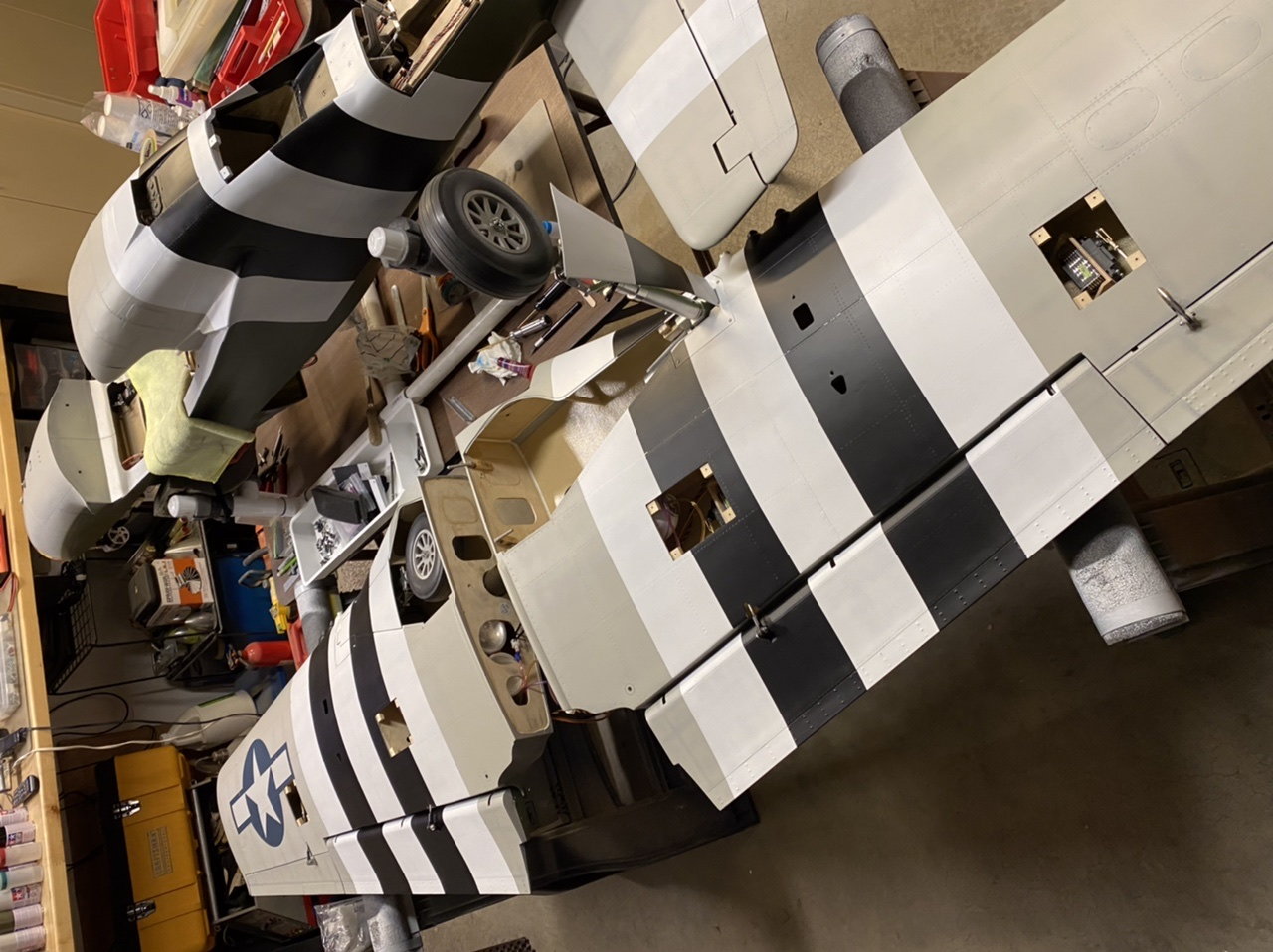
10-20-2021, 10:01 PM
#267
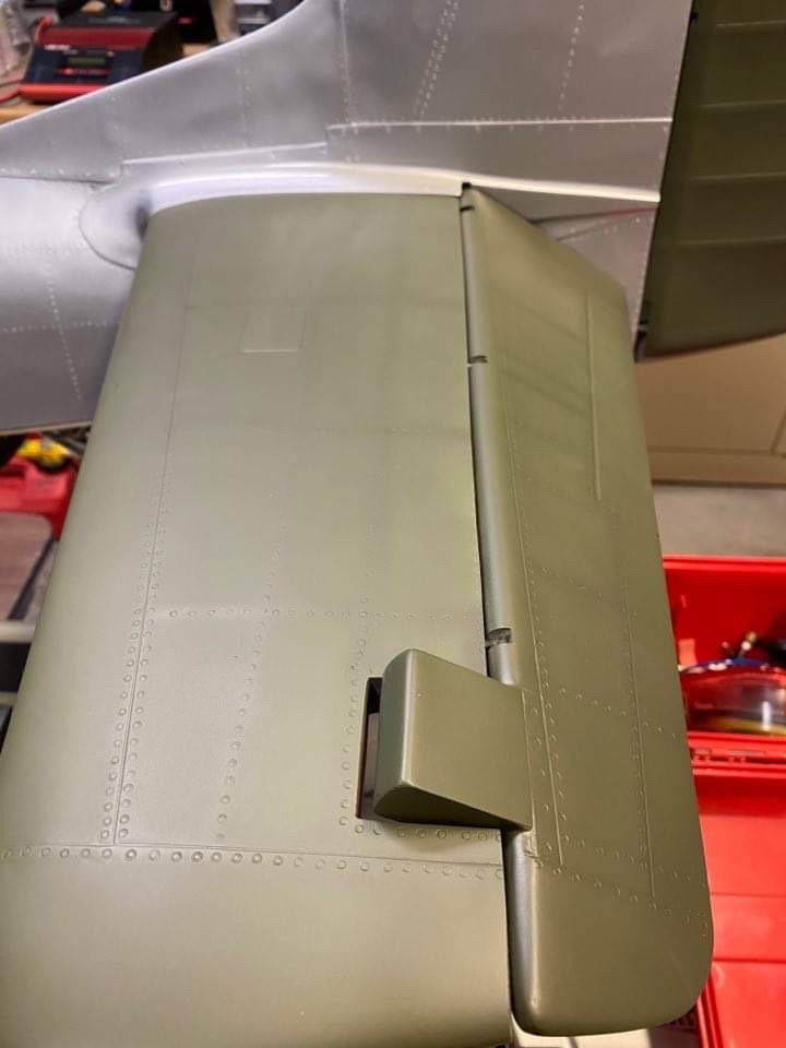
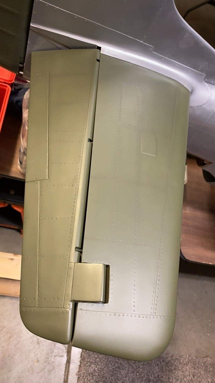
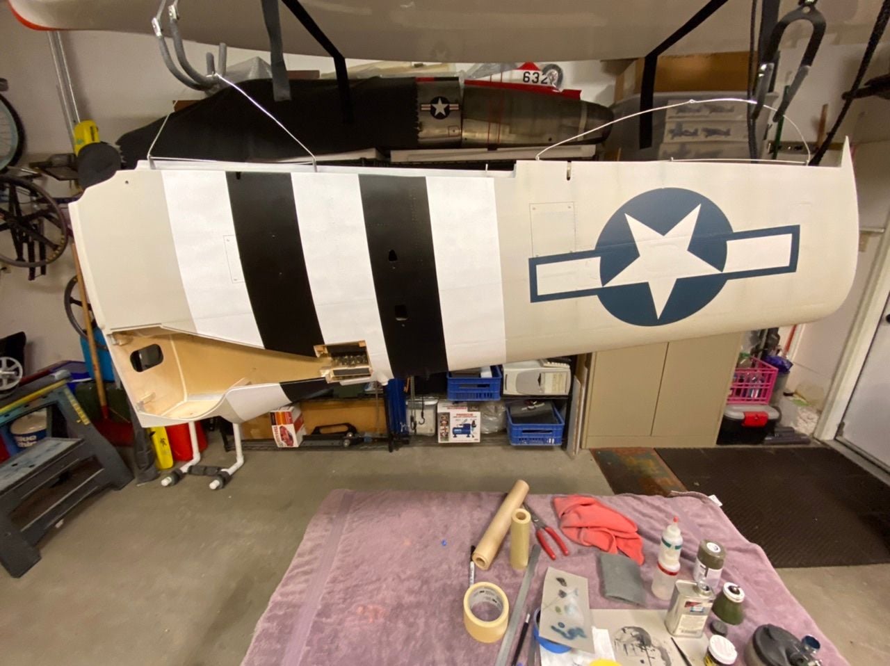
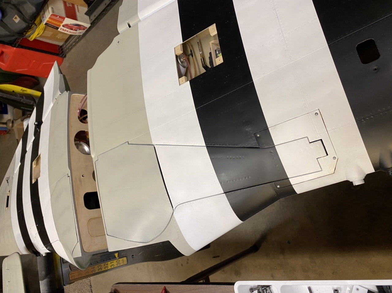
The wing is back together now and the outer doors are installed finally. Anybody doing this watch out for the pin alignment for the doors here. If the angles are off a little bit it turns into a nightmare and troubleshooting how it’s out of alignment. I have one that’s good and one that isn’t even after all the tweaking I did to set them up originally. So I found a happy medium position with a little bit of twist and called it good for now. Later I’ll revisit this problem and correct it.
The doors on this plane were a total disaster from new and I’ve had to cut adjust and modify them to fit like this. I spent a considerable amount of time on them and I’m still not happy with the gaps and fit but hopefully the invasion stripes distract you!
There’s another geometry problem in the flaps that I’ve double checked several times but it results in a 5mm difference in servo position relative to the wing spar. Even though the linkages are the same lengths there’s something going on with the flaps specifically. I have to verify it but I think the hinge center is not the same between the flaps. I epoxied the horns in the same location tangent to the hinge wire tube inside the flaps. Also you must keep in mind there’s nothing symmetrical about these wings or fuselage so you have to check as you go. Anyway the end result is I had to make the radio compensate on the flap throws and timing which I’m not a fan of because I like to keep things simple and direct.
10-21-2021, 02:23 PM
#270

The following users liked this post:
Chris Nicastro (10-21-2021)
10-21-2021, 02:57 PM
#272
My Feedback: (1)
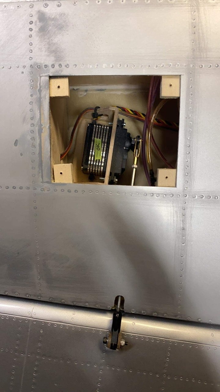
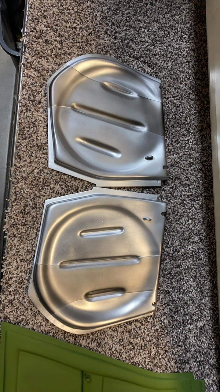
I have plenty of pictures.
Let me know if you need me to make any measurements,.
THis is factory direct from CARF (thailand??)
(meaning, i did not do this, it came like this)
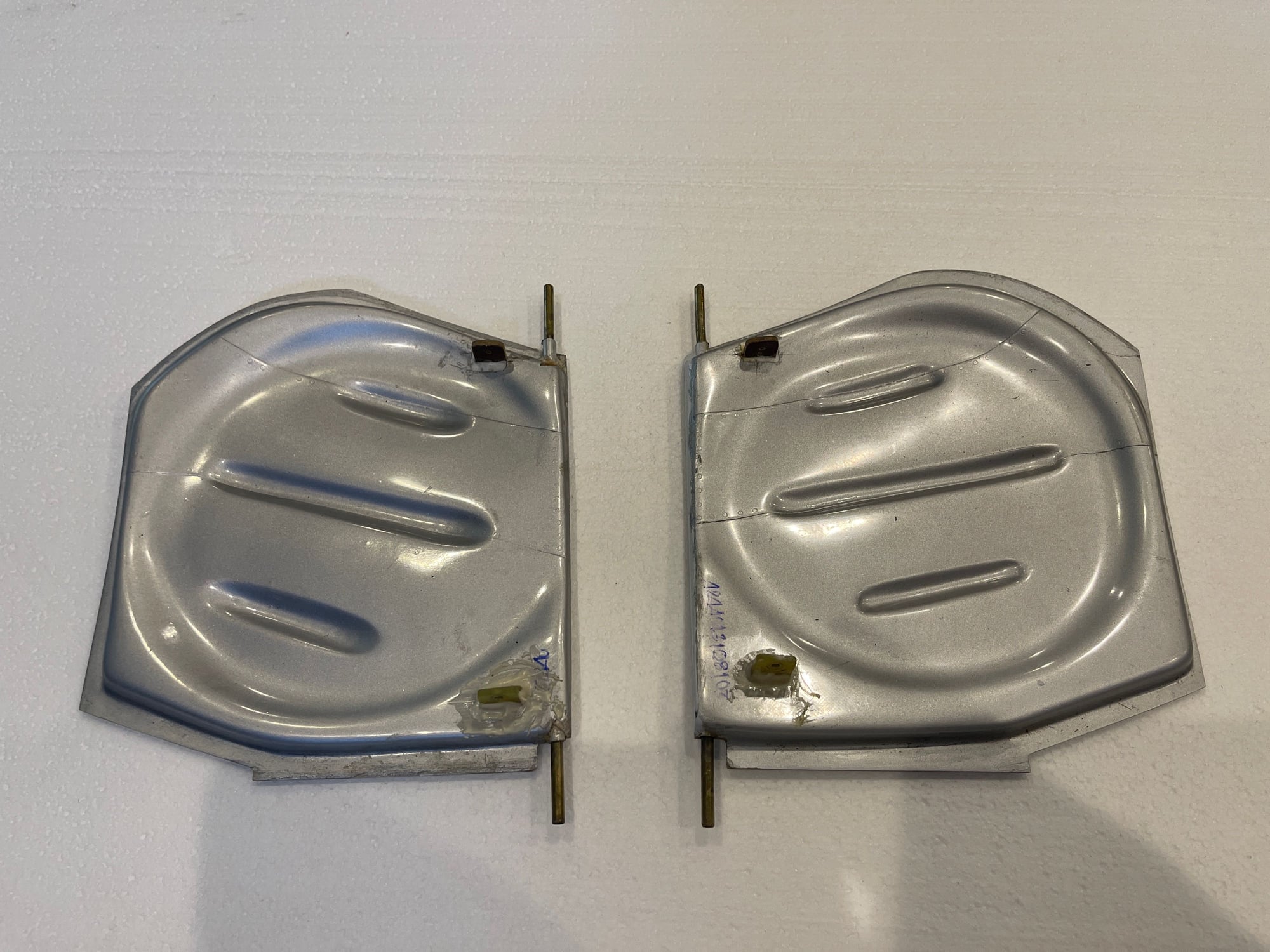
doors from CARF P51 GG
brass tube is removable.
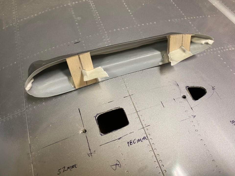
bottom side, brass tube extends almost 1 inch from front and from back side of door.
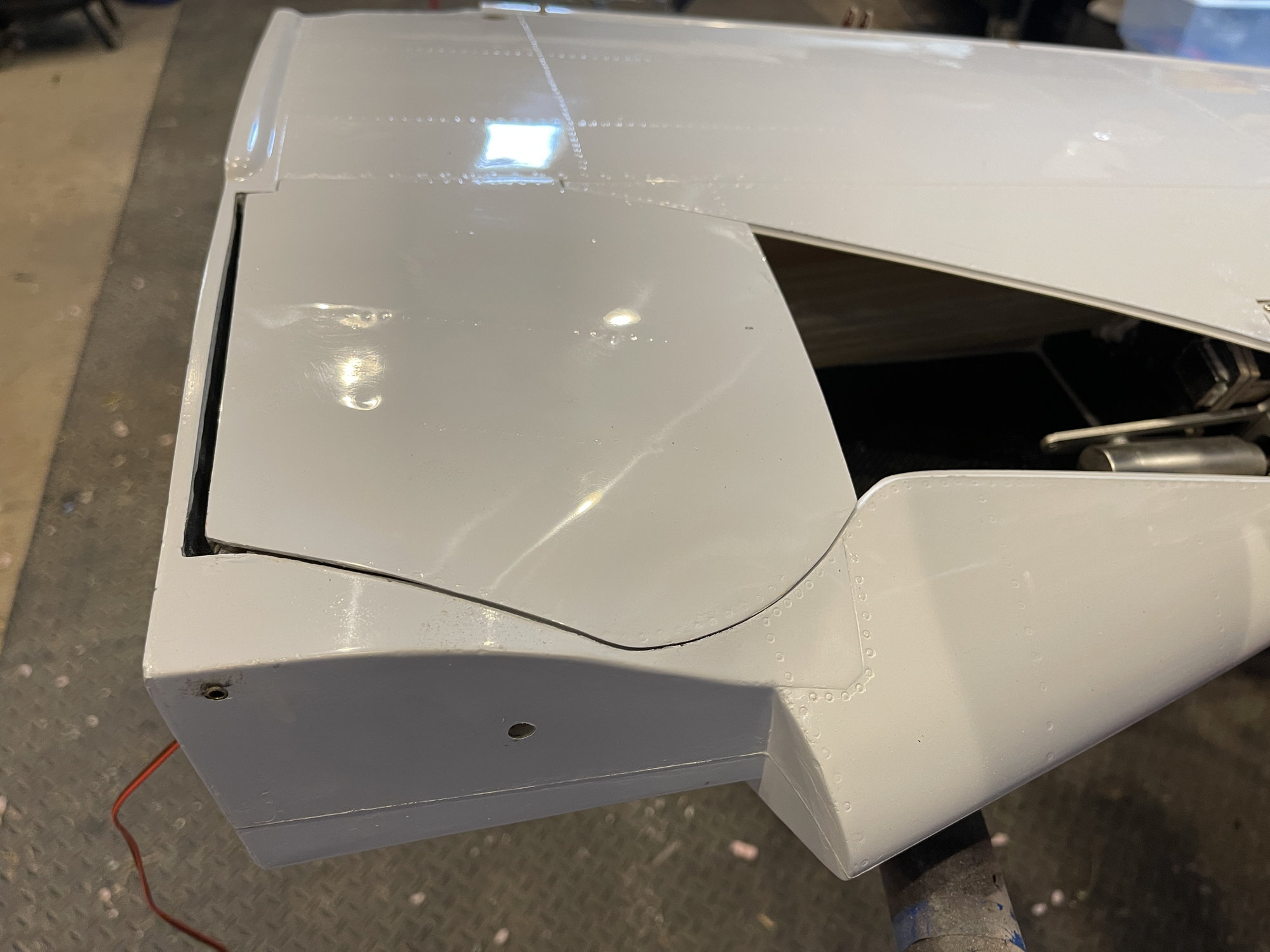
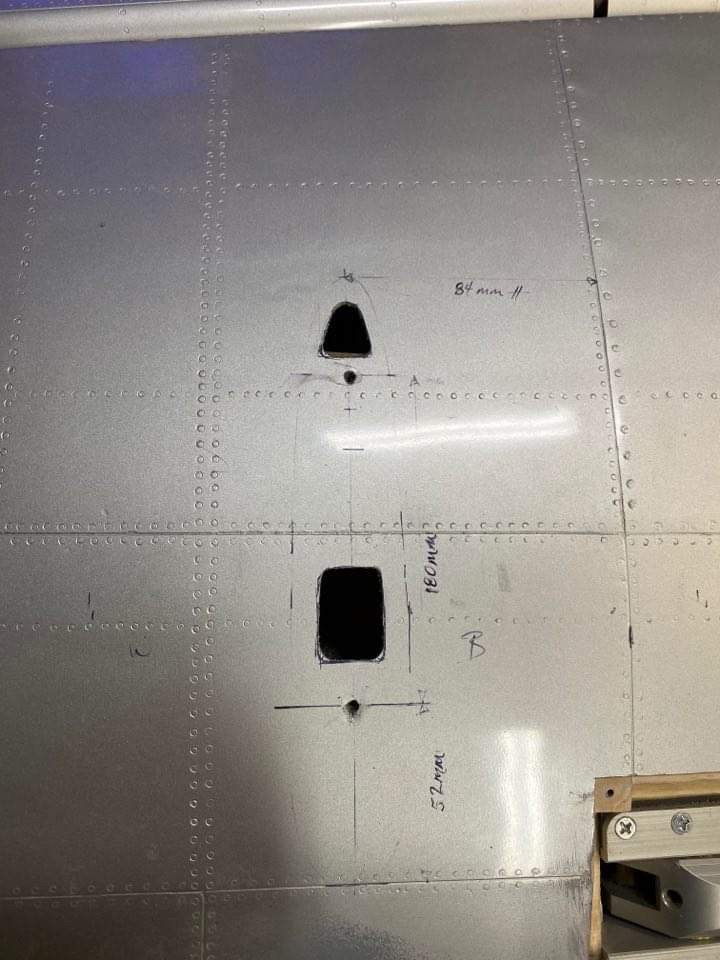
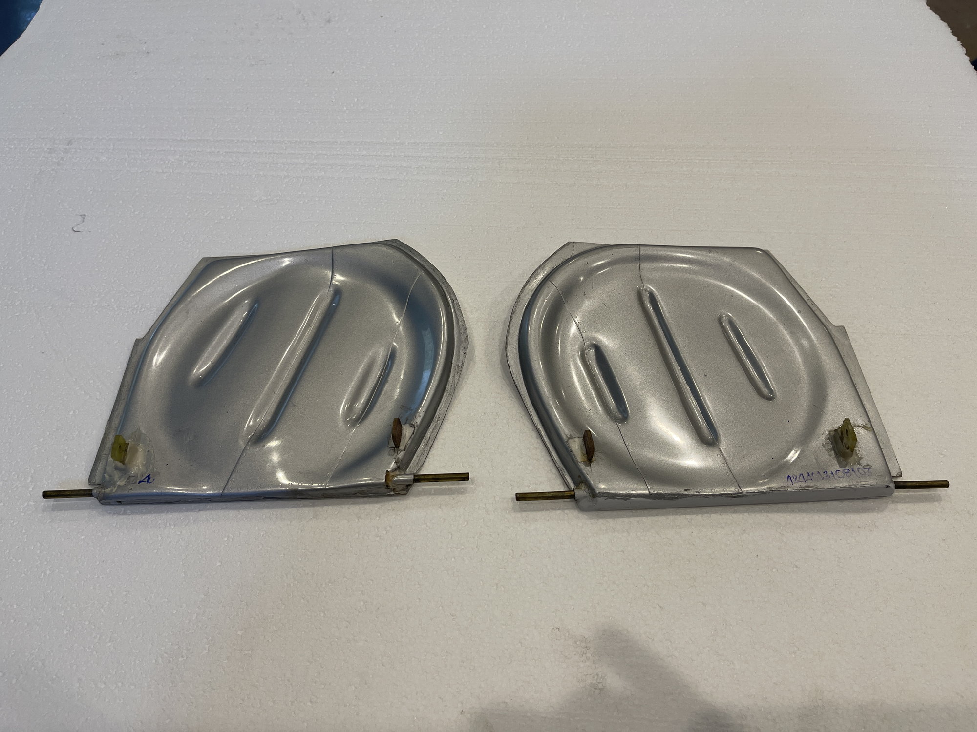
door closed, showing where the brass tube enters the front of the wing.
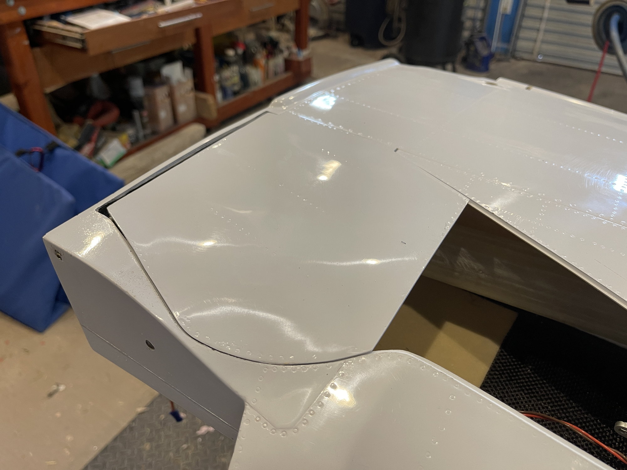
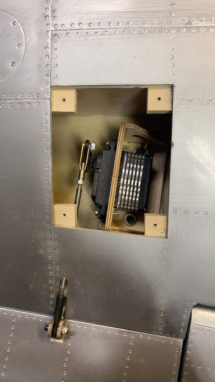
Door open
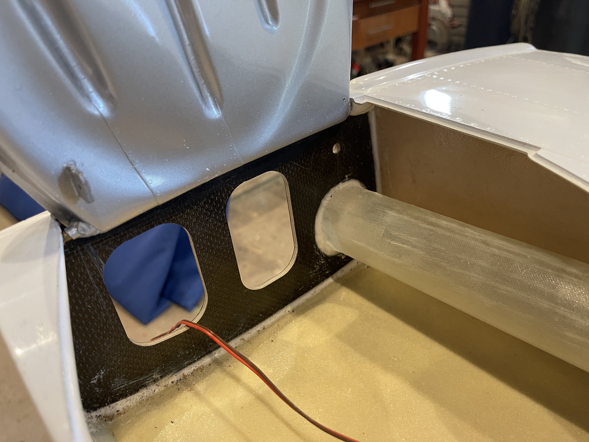
i grabbed the edge of the brass tube with a hemostat and pulled

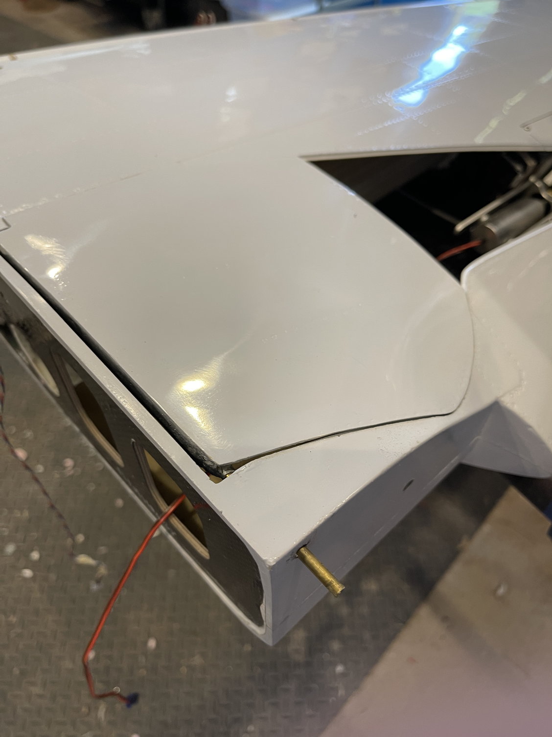
I was then able to grab it and pull it straight out.
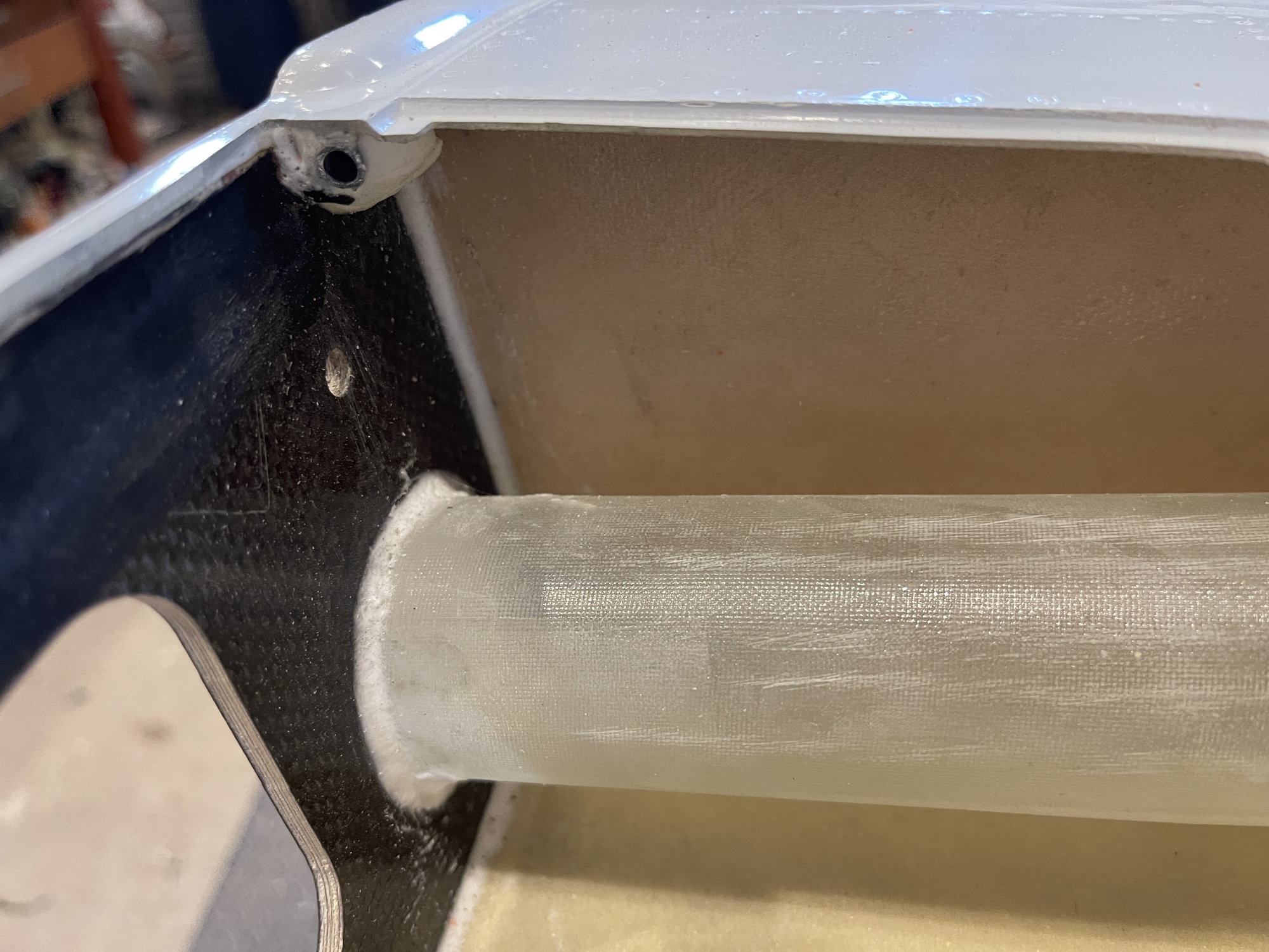
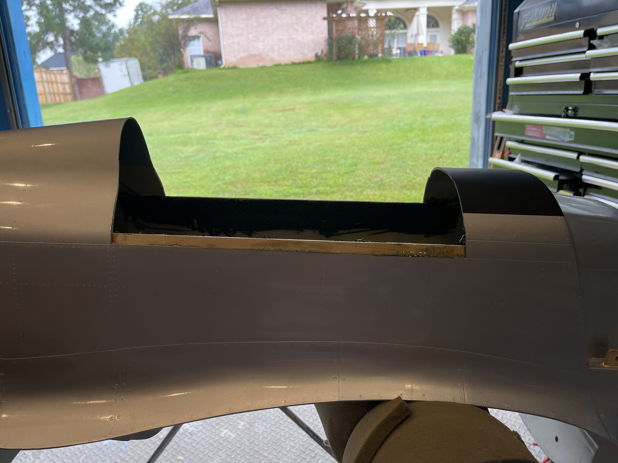
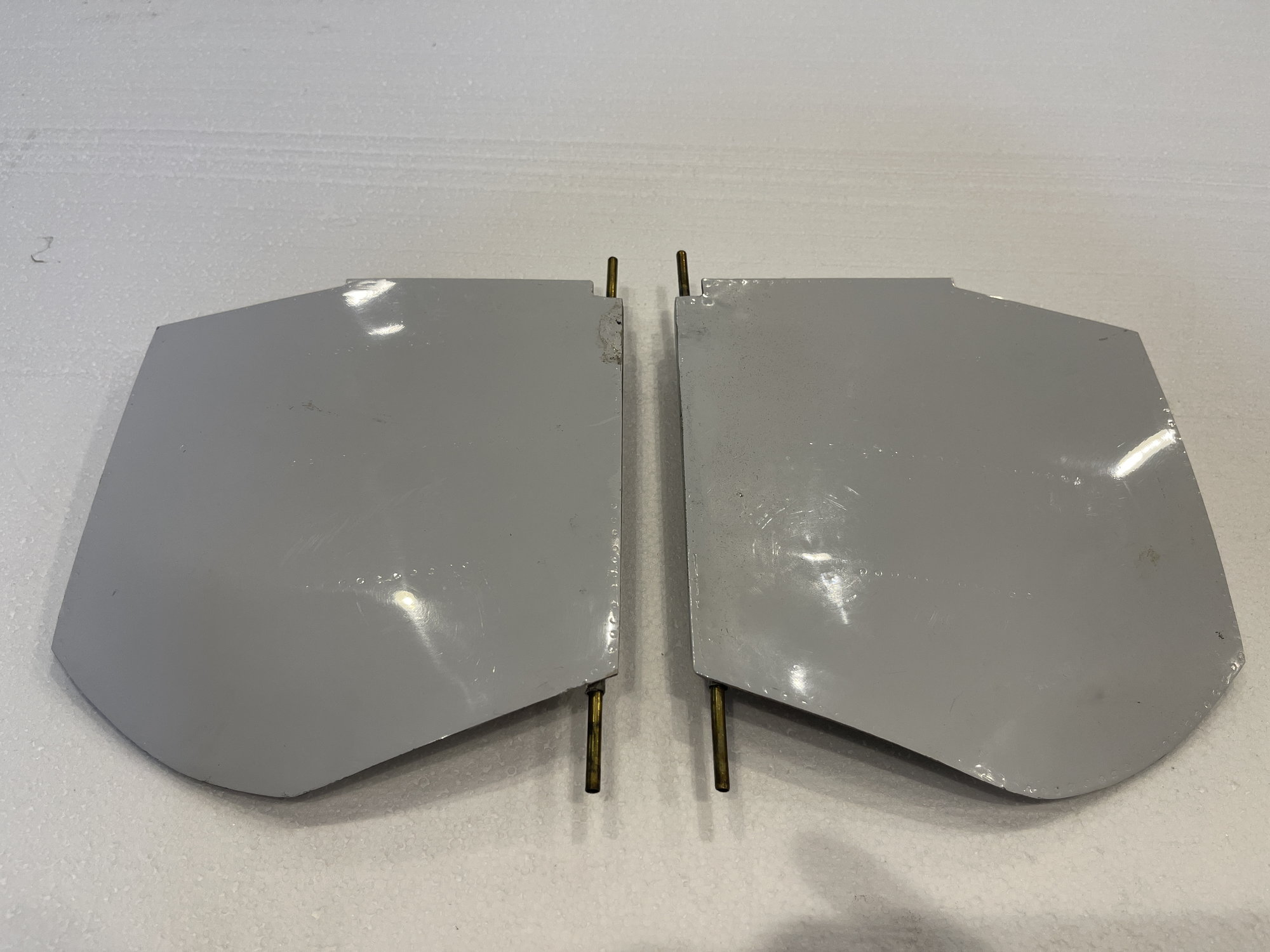
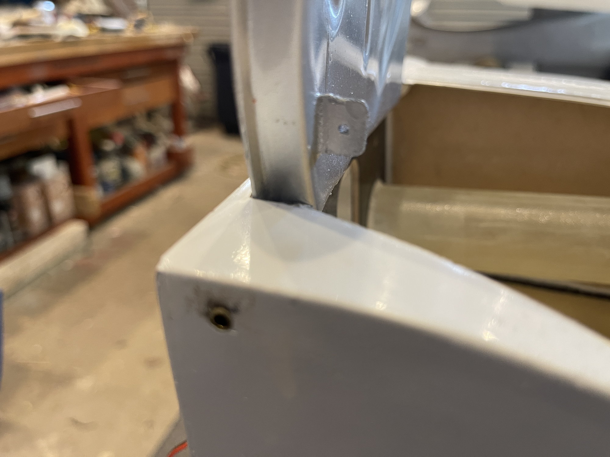
this is the rear aspect of door opening. Looks like aluminum tube, slihtly bigger than the brass tube, and it has that CHINA HYSOL
this is the front edge of the glued in aluminum tube.
Hope this helps
best regards,
Cam
Let me know if you need me to make any measurements,.
THis is factory direct from CARF (thailand??)
(meaning, i did not do this, it came like this)
doors from CARF P51 GG
brass tube is removable.
bottom side, brass tube extends almost 1 inch from front and from back side of door.
door closed, showing where the brass tube enters the front of the wing.
Door open
i grabbed the edge of the brass tube with a hemostat and pulled
I was then able to grab it and pull it straight out.
this is the rear aspect of door opening. Looks like aluminum tube, slihtly bigger than the brass tube, and it has that CHINA HYSOL
this is the front edge of the glued in aluminum tube.
Hope this helps
best regards,
Cam
10-25-2021, 06:46 PM
#273
Thanks for the photos, this was basically how mine came too.
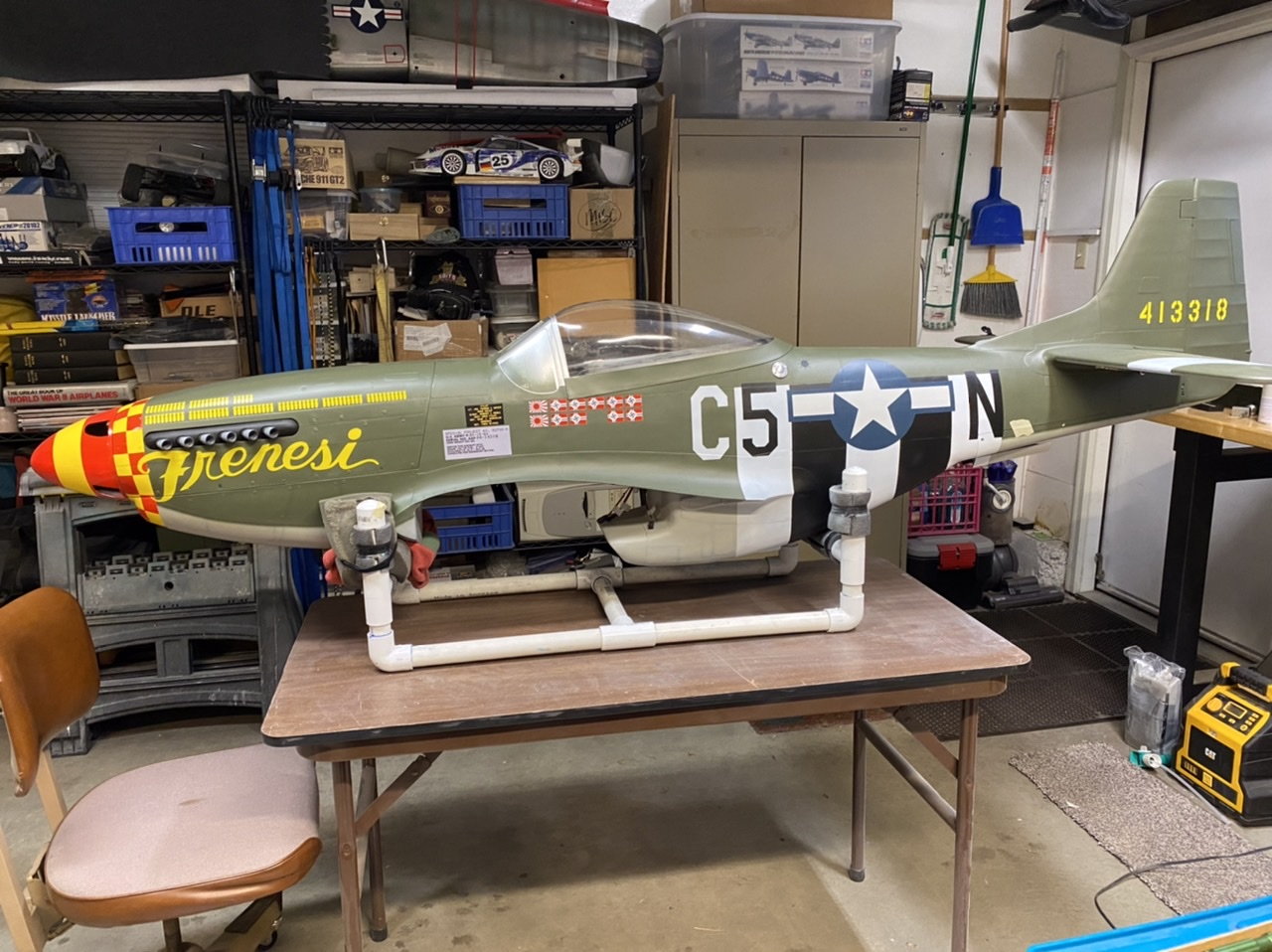
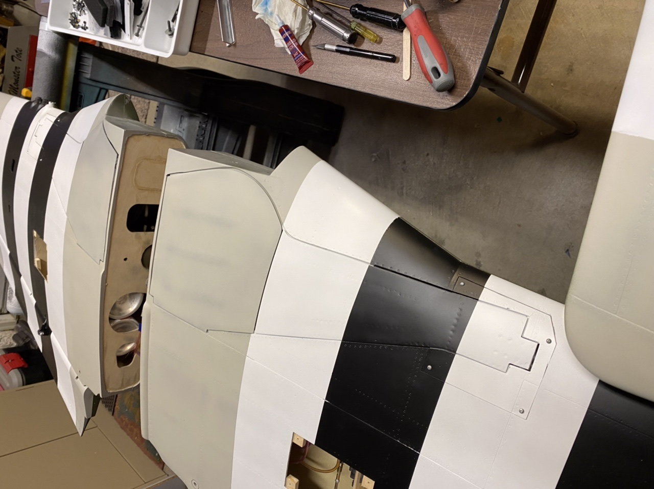
Nose art done! I had to piece this Frenesi graphic together but it looks ok I think. The F is 1/4 scale and the rest is 1/4.4 because I started the checkers based on 1/4 scale before I figured out the mask set was too big. Disaster averted, moving on!
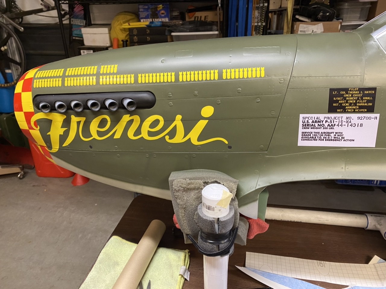
Nose art done! I had to piece this Frenesi graphic together but it looks ok I think. The F is 1/4 scale and the rest is 1/4.4 because I started the checkers based on 1/4 scale before I figured out the mask set was too big. Disaster averted, moving on!