LOCKHEED P-38J “LIGHTNING”. A giant 1/4 scale scratch built model
 07-04-2018, 01:41 AM
#1

Thread Starter

Join Date: Oct 2012
Location: ZARAGOZA, SPAIN
Posts: 97
Likes: 0
Received 0 Likes
on
0 Posts
Hello everyone.
Many of my flight partners know perfectly the giant project in which I am immersed for several years and have repeatedly asked me to expose it in this forum. Well, the limited availability of time to maintain the thread and the dedication that the design and construction of this model has imposed on me, have caused me to postpone the project's setting up..
With a few months until its completion, now I dare to introduce each and every one of the phases of the building process. I will go at my own pace, step by step, loading each and every one of the constructive sequences. So, please do not be impatient, the first one who wants to finish it is me.
I hope and I trust that you like it. I await your comments and suggestions, which everyone learns.
To begin with, a summary and some history.
Last edited by fbielsa; 07-04-2018 at 01:56 AM.
 07-04-2018, 01:46 AM
#2
Thread Starter
Join Date: Oct 2012
Location: ZARAGOZA, SPAIN
Posts: 97
Likes: 0
Received 0 Likes
on
0 Posts
The P-38 Lightning is a beautiful and emblematic airplane that arouses admiration in any scenario. However, its presence in our flight tracks is very limited. To understand this paradox we must analyze its antecedents: it is a twin engine with special characteristics, high wing load, constructive complexity and high level of equipment, which, together with the great distance between its power plants, make it sadly known for its facility to get into an uncontrolled spiral of death when an engine fails. In addition, for the mere fact of being a twin-engine, we should not expect twice as many problems, as you might think, but multiplied by four. In short, a plane not recommended by the erudites at the time of approaching the construction of a multi-engine.
But one good day, as is usual in this trade, his special magnetism made boldness prevail over prudence and start the project to the cry of ... now or never! Two fuselages, a central gondola, pneumatic tricycle train, two engines, special electronics ..., in short, a lot of work, but nothing that, with time and care, could not be solved. And the desire to design everything as large as my transport vehicle would allow, which resulted in a quarter-scale model, was the definitive incentive to start its construction. So, after the relevant bibliographical compilation, I started working seven years ago.
Although all the phases of the project have been exciting, I admit that I will not fully ponder the aforementioned drawbacks and I have gone through times in which I have seen myself quite surpassed. Its delicate design, the laborious construction, its endless fairings and the complicated set-up, magnified by the large size of the model, have been pitfalls that almost truncated all my illusions placed on it. Finally, obstacles have been overcome based on tenacity, patience and invaluable collaborations of good fellow fans, but I feel that this time the bar has been very high. So much, that I doubt my future capacity to undertake another similar project. I'll have to take some time to know the answer.
07-04-2018, 01:56 AM
#3
Thread Starter
Join Date: Oct 2012
Location: ZARAGOZA, SPAIN
Posts: 97
Likes: 0
Received 0 Likes
on
0 Posts
The real plane
Known by the Germans as "Der Gabelschwanz Teufel" (fork-tailed devil) and by the Japanese as "Two planes with a pilot", the P-38 Lightning was considered the most advanced aircraft of the moment. It was the first fighter aircraft to have a tricycle gear, a metallic coating assembled with flush rivets, turbochargers and assisted control surfaces, which, together with its two powerful Allison 1710 engines of 12 cylinders and 1700 hp in conditions of emergency, they turned it into the fastest fighter (720 km / hour) and with more autonomy (6112 km with auxiliary tanks) to date. A total of 10037 units were built.
Its conception and special physiognomy were mainly due to the Chief Engineer of Lockheed, Clarence Leonard "Kelly" Johnson, who, in 1937, following a previous assignment from the United States Army Air Corps (USAAC) that was looking for an interceptor of high altitude, well armed and able to ascend in less time than any competitor, proposed a solution consisting of two powerful engines, each on a long, stylized fuselage with its own drift, both joined by a large horizontal stabilizer, which would allow to locate the pilot in a central gondola and concentrate all the shooting power in the nose.
The prototype XP-38 successfully flew for the first time on January 27, 1939, but experienced a problem of buffetting in the horizontal stabilizer that advised arranging the rotation of an engine in the opposite direction (YP-38), although it was not solved. all the way up to the P-38D model in 1941, the first type of Lightning manufactured in series prepared for combat, when it was equipped with the characteristic fairing frontal union of the wing to the gondola.
The airplane incorporated several later improvements in terms of motorization, cooling, armament and assistance of controls, but it was not until the P-38J, in August of 1943, when "the definitive Lightning" was achieved. Its high speed, capacity of ascent, power of shot and improvement in the maneuverability, not only equaled but surpassed those of any fighters of the time. In fact, 2970 "J" units were built. In addition, electric recovery flaps under the wings, which were equipped with the last 210 units of this series from June 1944 (P-38J-25-LO), solved the loss of support that the compressibility produced when trying leave a prolonged diving at more than 900 km / hour. Although other later variants were constructed in greater number (P-38L, P-38M, etc.) that contributed improvements of power and armament, they did not eclipse the engineering success that supposed the series "J".
The P-38 Lightning was a decisive aircraft in the battle of the Pacific, where it reaped innumerable victories against the Japanese army. He also participated successfully in the battle of the Mediterranean and in the Normandy landings against the German army, although in this theatre he suffered more casualties. The arrival of the powerful and agile P-51 Mustang at the end of 1944, much cheaper to maintain, ended up relegating the P-38 to more specific combat tasks.
07-04-2018, 09:31 AM
#4
Thread Starter
Join Date: Oct 2012
Location: ZARAGOZA, SPAIN
Posts: 97
Likes: 0
Received 0 Likes
on
0 Posts
Design of the model
The first step was to decide the scale. As I wanted a large model to optimize the wing load and my vehicle allowed to reach the 1/4 scale (3.7 meters of wing span) I directed my research in that direction. What a surprise to see the shortage of such great precedents around the world, counted, even today, with the fingers of one hand. Surely the limit of 25 Kg and the absence of similar commercial kits had much to do.
The first step was to decide the scale. As I wanted a large model to optimize the wing load and my vehicle allowed to reach the 1/4 scale (3.7 meters of wing span) I directed my research in that direction. What a surprise to see the shortage of such great precedents around the world, counted, even today, with the fingers of one hand. Surely the limit of 25 Kg and the absence of similar commercial kits had much to do.
07-04-2018, 09:32 AM
#5
Thread Starter
Join Date: Oct 2012
Location: ZARAGOZA, SPAIN
Posts: 97
Likes: 0
Received 0 Likes
on
0 Posts
Concerned about this finding, my effort focused on getting a landing gear capable of supporting a model of such dimensions, with acceptable details of model and, if possible, a manufacturer with proven experience. If this was not feasible, much to my regret, I would have to reduce the scale. To do this, I contacted the American house Sierra, which initially showed great interest in its custom construction, but, after checking the lack of reproducibility among its customers, gave up the order without further consideration.
07-04-2018, 09:34 AM
#6
Thread Starter
Join Date: Oct 2012
Location: ZARAGOZA, SPAIN
Posts: 97
Likes: 0
Received 0 Likes
on
0 Posts
At the end, advised by my good friend Paco García-Cuevas, I contacted the German house Hawe Modelltechnik where, this time with great professionalism and enthusiasm, they manufactured a robust landing gear, the chosen size and with excellent details of scale, requesting final photographs when it was mounted in. Now I had the free way to develop the project.
Last edited by fbielsa; 07-04-2018 at 10:07 PM.
 07-05-2018, 10:42 AM
#8
Thread Starter
Join Date: Oct 2012
Location: ZARAGOZA, SPAIN
Posts: 97
Likes: 0
Received 0 Likes
on
0 Posts

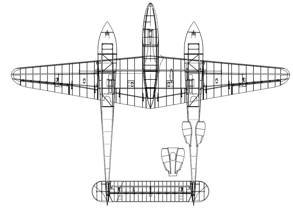
The second step was to make a good structural design. It was very clear that in this twin-engine lightness should prevail without sacrificing robustness, especially when, in my hands, only the landing gear weighed 6 Kg. Not to mention the two full engines that would be at least 6 Kg plus.
With these premises, no matter how light the structure was, sure that the limit of 30 Kg was going to be exceeded in the model. Scared by the look that was acquiring the project, it was necessary to decide the type of construction, classic or with plastic materials, taking into account that, in these scale, the constructive standards are changed and you have to imagine everything necessary to guarantee the structural resistance.
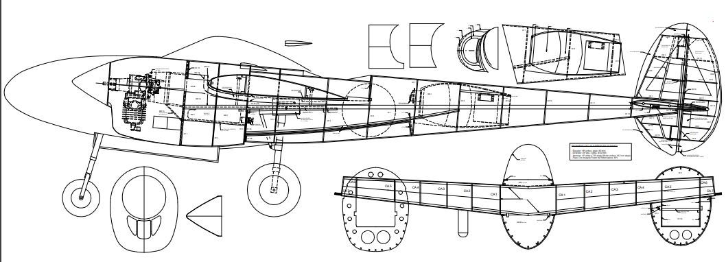
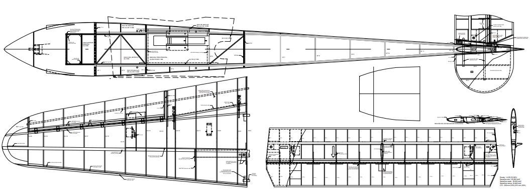
As I had the original plan of the Nick Ziroli model at a scale of 1/5 in wood, the logic advised to maximize it to save time, but with this practice the construction material is oversized and the final model is unnecessarily over-weighted. On the other hand, although attractive, the idea of doing "all fiber-glass" raised a priori the disadvantages of the weight and the work invested to build a single unit. So I opted for the solution of drawing my own CAD drawing, based on the original cuts and commercial plans, but providing own structural solutions that have resulted in a weight in flight order of 35 Kg, which is quite good, given the high wing loading of other smaller P-38s. In fact, according to the formula recommended by Pierre Rousselot (“Realisme de vol et effet d’echelle”. M.R.A. 568-570. 1987), who applies the coefficient E3,22 to the scale chosen to achieve flight realism and which has given me such good results in other models, the model should have weighed about 54 Kg. "empty", so I have managed to reduce the expectation more than 30% and use less powerful engines than expected.
Some pics of my self-drawn plan
Last edited by fbielsa; 07-05-2018 at 10:48 AM.
07-07-2018, 08:25 AM
#9
Thread Starter
Join Date: Oct 2012
Location: ZARAGOZA, SPAIN
Posts: 97
Likes: 0
Received 0 Likes
on
0 Posts
It is a classic structural design, with plywood frames and ribs, samba and spruce spars, and balsa sheeting, but with fairings, gates and a large number of components, made in very lightweight "composites". Even so, more than 300 pieces of wood, not counting the profuse spars and other stuff, so it was to be grateful for the help of my friends Alberto Barrios and José Vicente Crespo to cut all these pieces, ribs and frames with a CNC milling machine, taking advantage of my design in CAD. Good thing, because if not, I'd still be cutting by hand.
Finally, I thought about previously having the engines to adapt the benches and fairings to them, although, consulting its dimensions in advance, I opted to acquire them later. For the calculation of the enginepower, again I applied the corresponding Rousselot coefficient. The power of the real plane is divided by E3,22, which advised from 11.5 to 13 hp per engine for a realistic flight. So, foreseeing my savings in the final weight, with about 9 hp I thought it would be enough
Finally, I thought about previously having the engines to adapt the benches and fairings to them, although, consulting its dimensions in advance, I opted to acquire them later. For the calculation of the enginepower, again I applied the corresponding Rousselot coefficient. The power of the real plane is divided by E3,22, which advised from 11.5 to 13 hp per engine for a realistic flight. So, foreseeing my savings in the final weight, with about 9 hp I thought it would be enough


 07-09-2018, 02:51 AM
#13
Thread Starter
Join Date: Oct 2012
Location: ZARAGOZA, SPAIN
Posts: 97
Likes: 0
Received 0 Likes
on
0 Posts
When I chose the type of engine, unfortunately the existing single-cylinder 4-stroke offer fell short of power, while that of the two-cylinder in-line (the boxer protrude under the cowl) was excessive.
In addition, due to the cooling problem that the rear cylinder of the latter use to produce and its obligatory inverted positioning, they did not seem appropriate for such a critical twin engine. There is no need to overpower an airplane like this one, as it would be disastrous if one of them stops.
Another aspect that I valued was the use of engines of counter rotation, for that of the fidelity with the original; Although it is known that they do not provide real benefits in the maneuverability and stability of the rc-models, I really underestimated them because of the difficulty of finding three-blade inverted propellers so large that they guarantee the same performance in both engines.
So, I finally decided on two simple single-cylinder 2-stroke normal turn that I acquired throughout the construction.
As with the landing gear, I did not succeed in the initial choice of the brand of engines, this time for pledging to acquire them to EVO, a Spanish manufacturer by that time located in Granada and now disappeared. With the hope of endowing my plane with two engines "made in Spain", the only thing I got in return were false promises and a lot of dislikes, so I had to opt, fortunately, for another brand, this time of recognized prestige and seriousness in service.
Last edited by fbielsa; 07-09-2018 at 03:18 AM.
07-09-2018, 09:12 AM
#14
Thread Starter
Join Date: Oct 2012
Location: ZARAGOZA, SPAIN
Posts: 97
Likes: 0
Received 0 Likes
on
0 Posts
It is not excessively complex, but requires experience due to the size of the model and the necessary accuracy in the alignment of a model of these characteristics. It is advisable to have at least two work benches simultaneous with accessibility on all four sides to significantly reduce working time, which is just what I did not have, so the construction has taken me several years. And what is more important, in several phases of the building the airplane must remain completely assembly during days, reason why also it is necessary to a diaphanous surface of about 15 m2 (161' - 66'' f2) that does not interfere with other familiar interests.
07-09-2018, 09:25 AM
#15
Thread Starter
Join Date: Oct 2012
Location: ZARAGOZA, SPAIN
Posts: 97
Likes: 0
Received 0 Likes
on
0 Posts
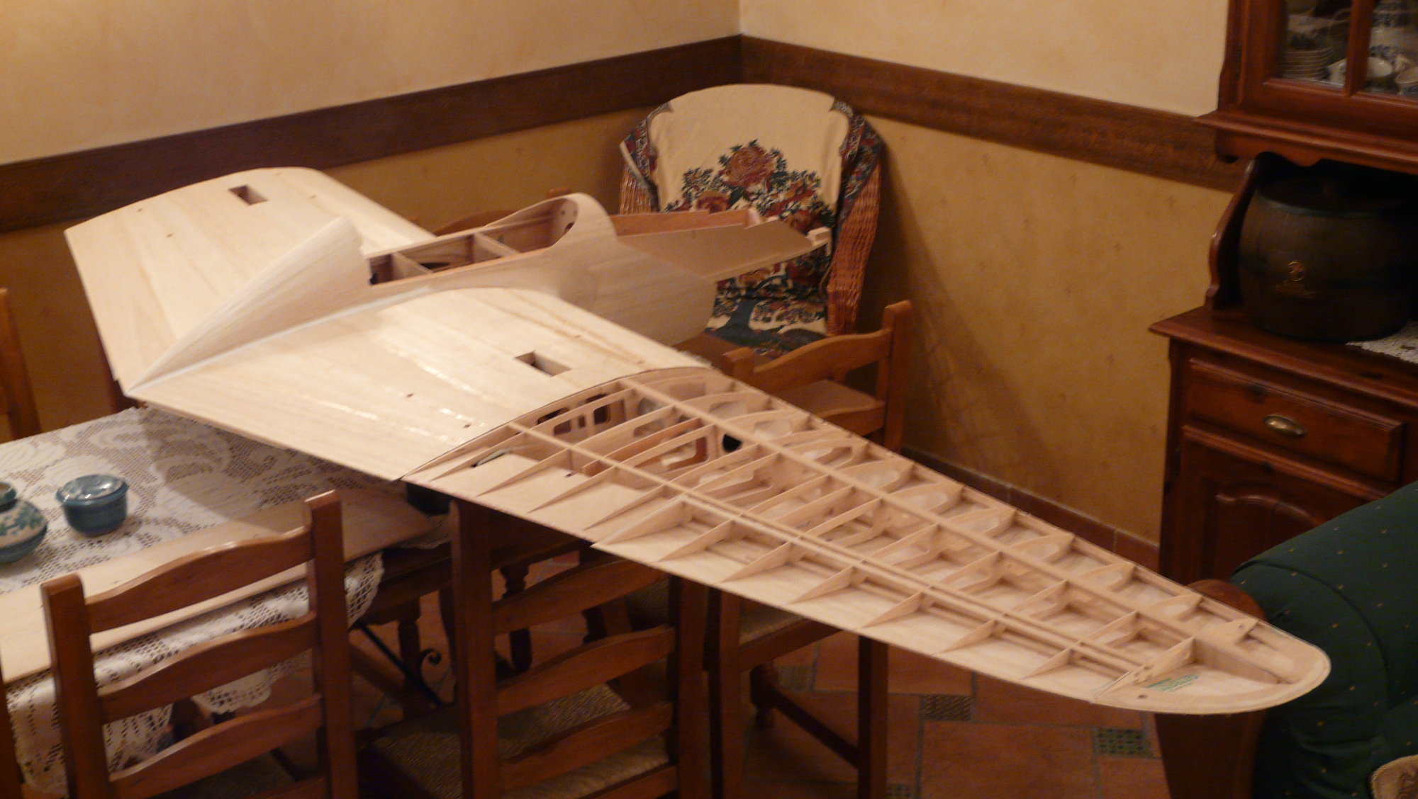
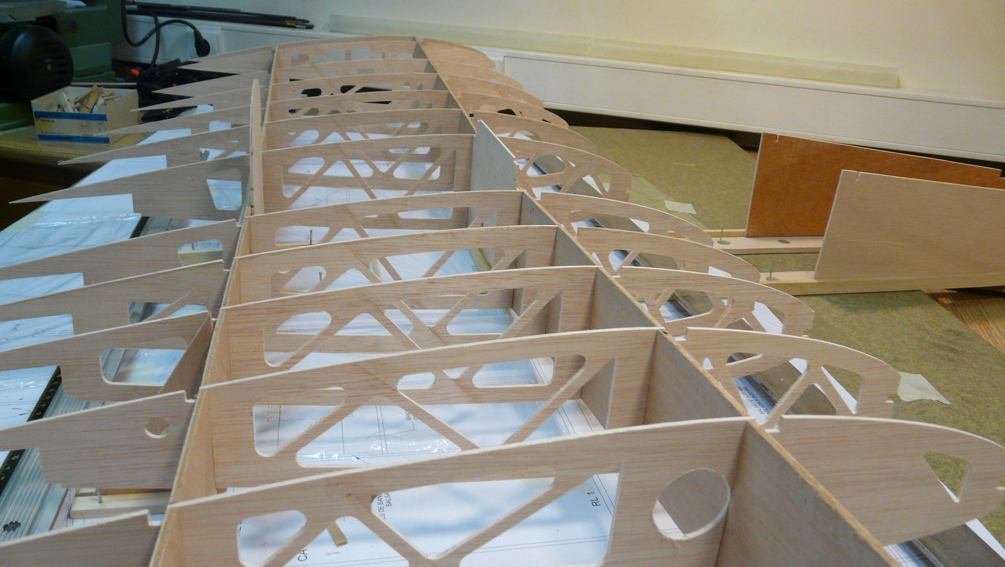
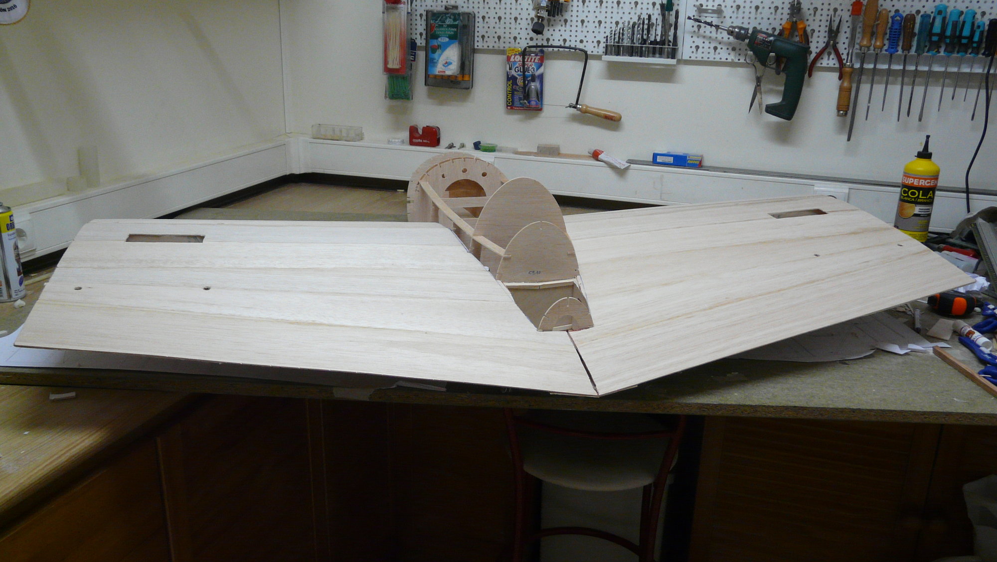
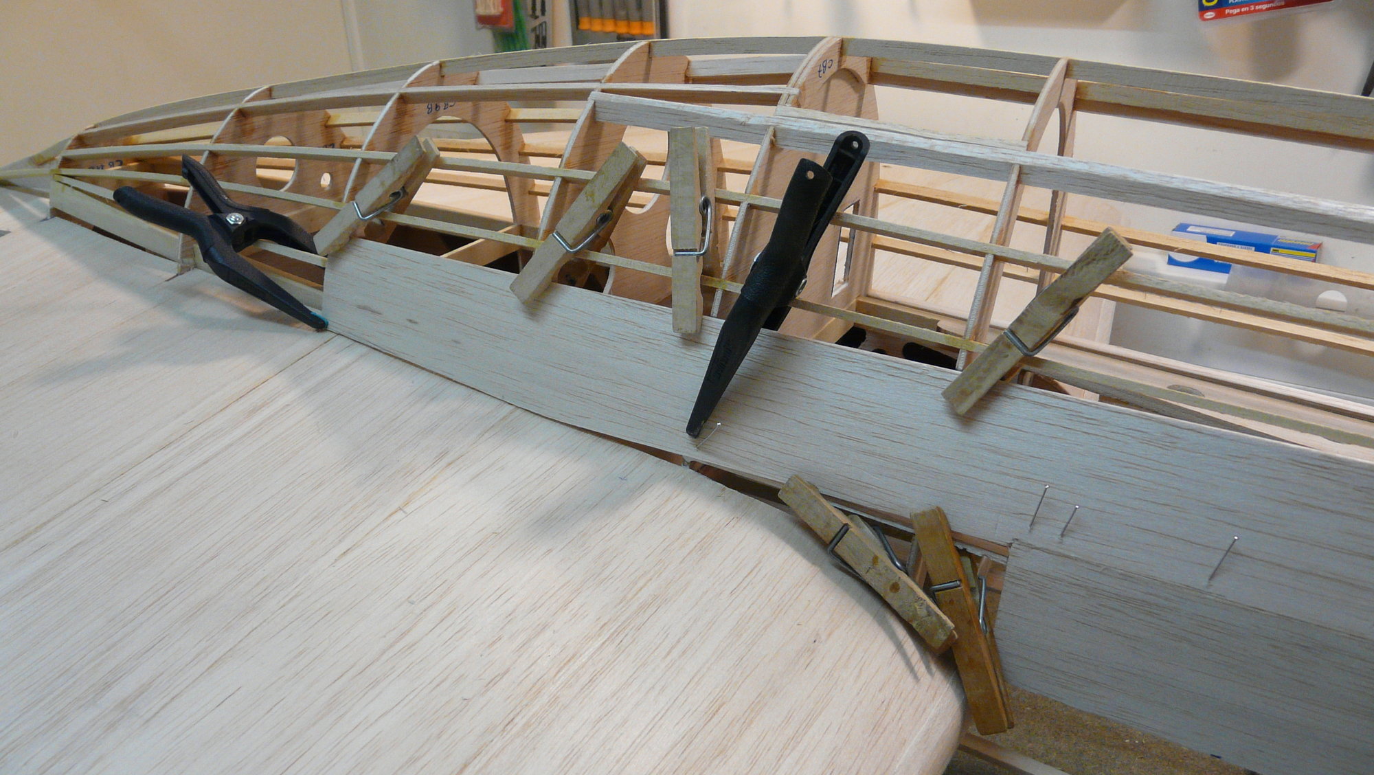
Center fuselage and wing center section
A 160 x 85 cm (63'') mounting board is required to build the entire assembly in a single module. This last aspect really conditions the transport, but provides greater lightness and rigidity to obviate reinforcements and unsightly unions by the sinuous central wing fairing ("kármán"), which would be required if you made the nacelle detachable and independent of the central wing.
It is built following the Nick Ziroli method, on a crutch formed by two main spars in samba wood of 7 x 14 mm and crosspieces in a balsa wood of 3 x 14 mm, which is assembled over the plan.
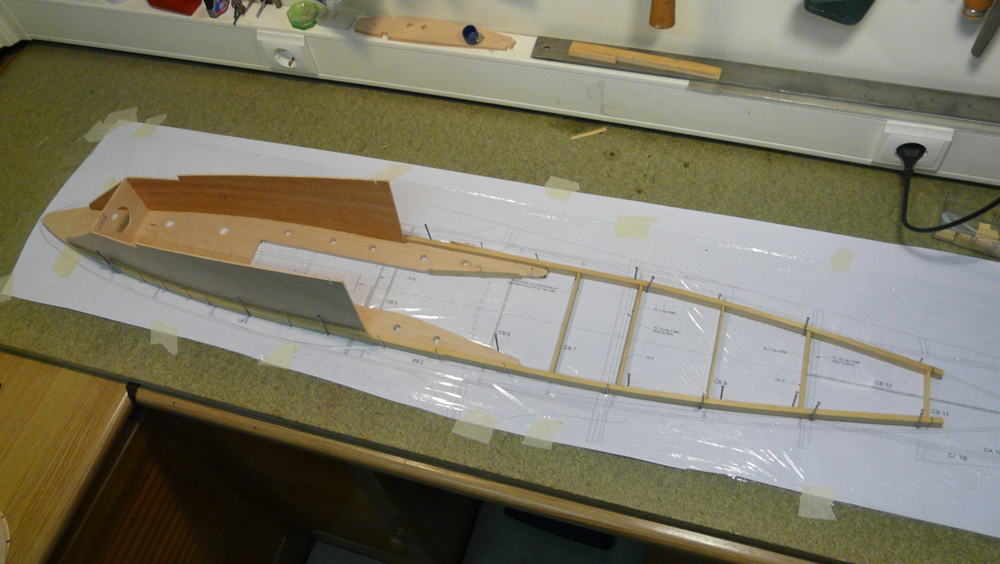
07-09-2018, 09:50 AM
#16
Thread Starter
Join Date: Oct 2012
Location: ZARAGOZA, SPAIN
Posts: 97
Likes: 0
Received 0 Likes
on
0 Posts
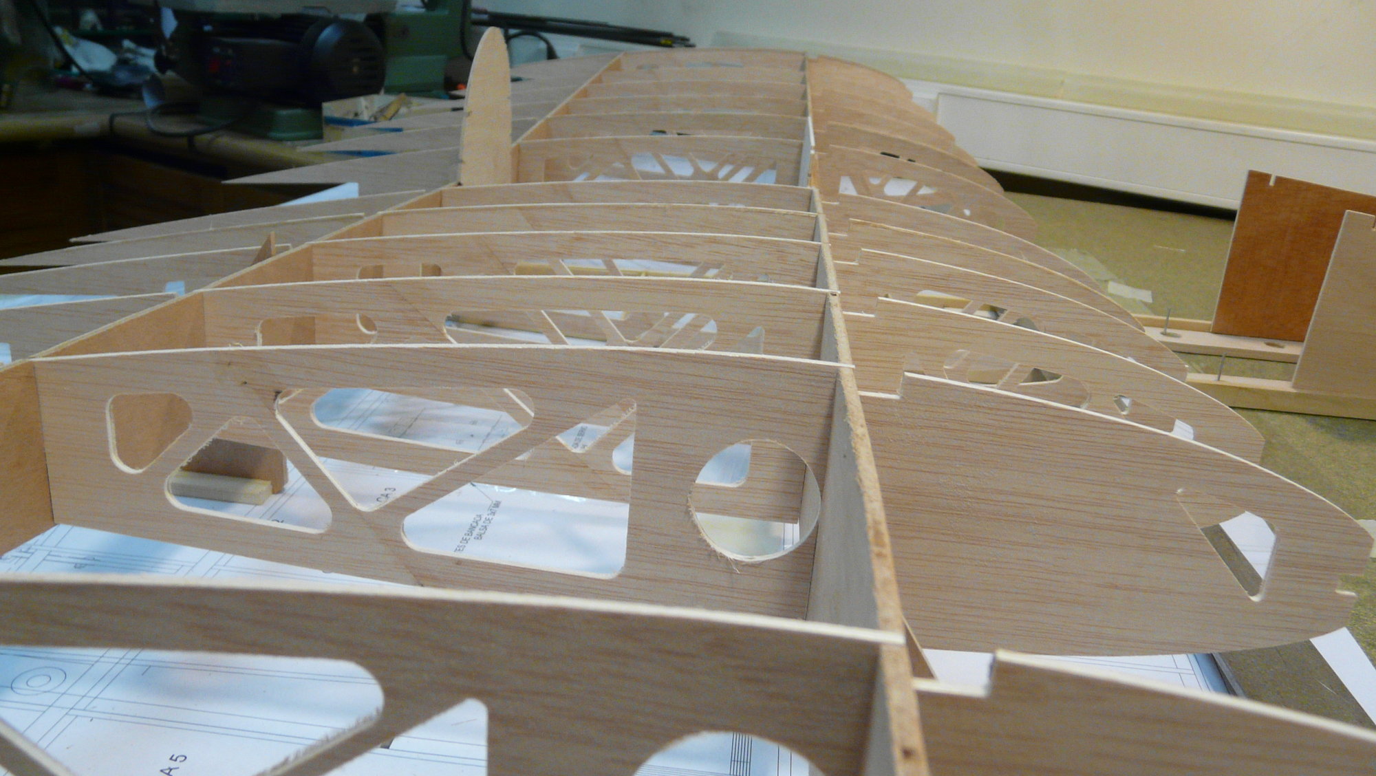
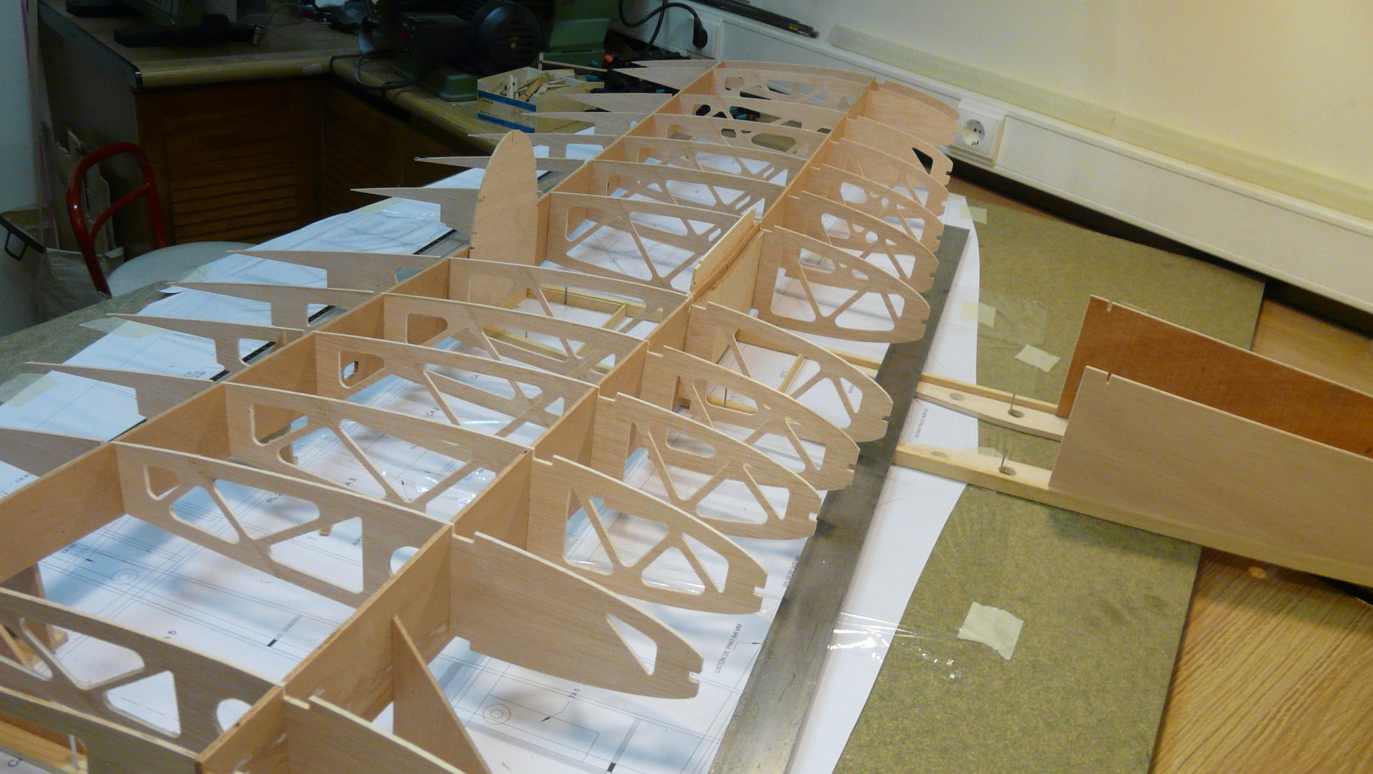
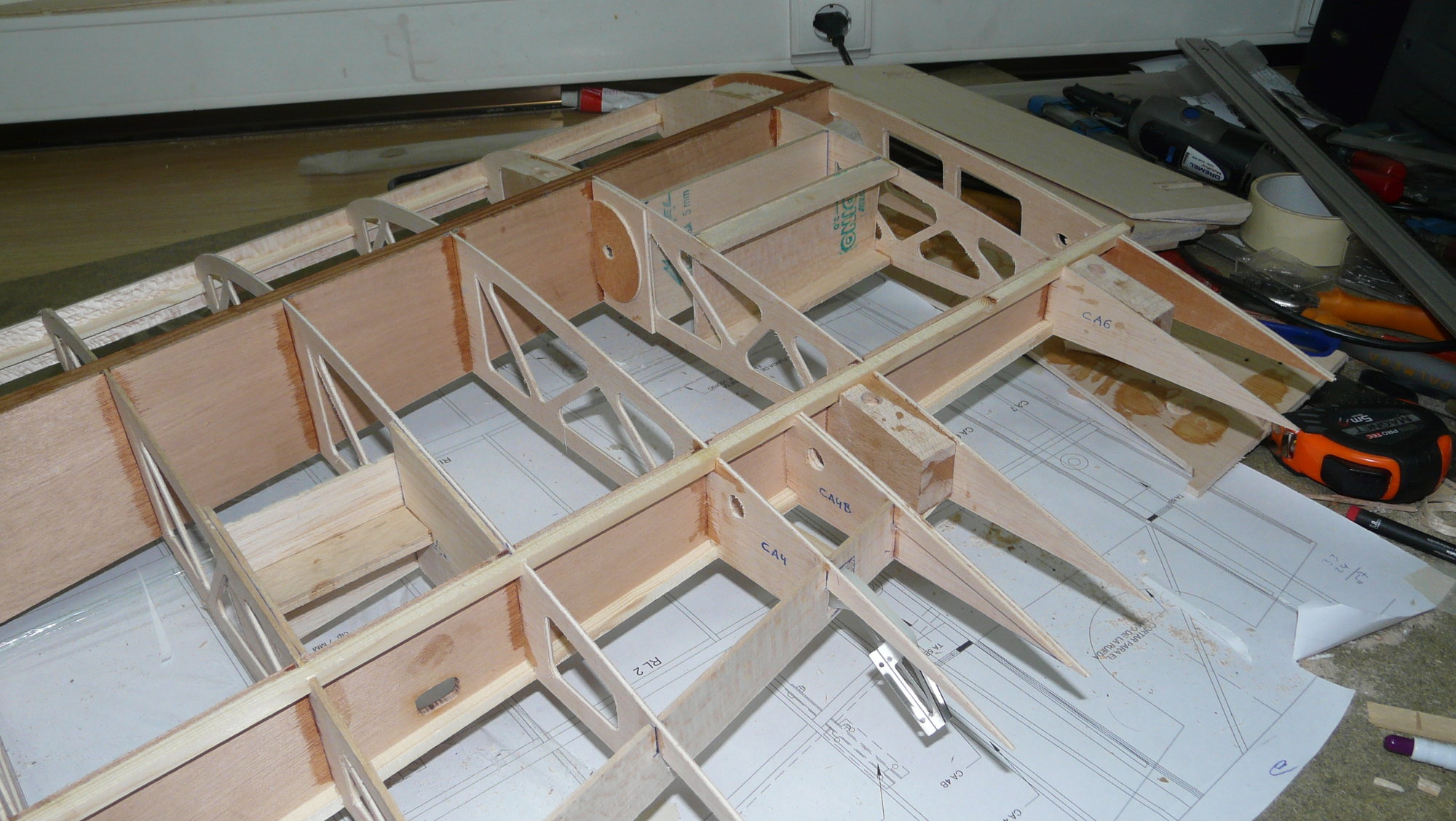
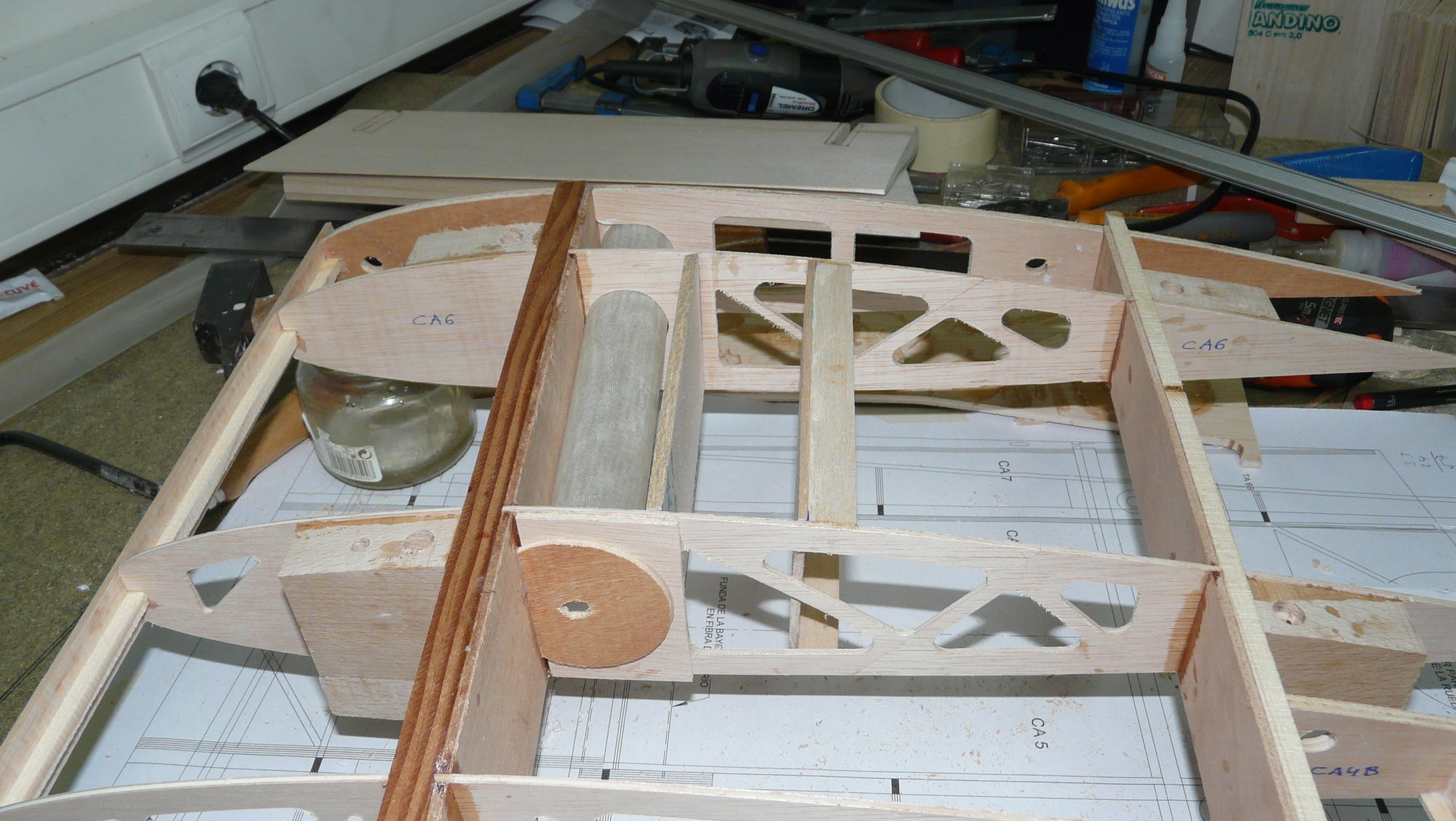
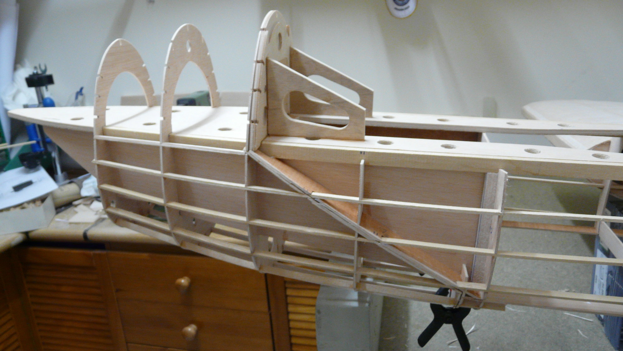
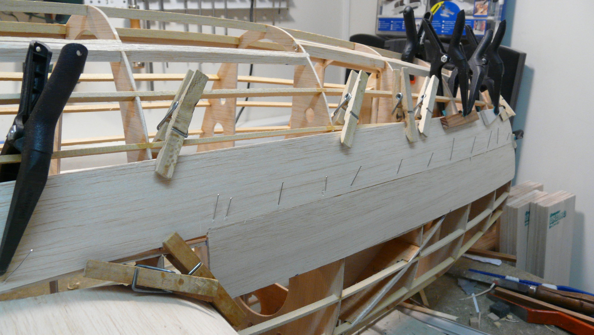
Then, are added the 1/3'' ply nose wheel mount, the 1/8' ply upright walls, the master formers and the two vertical wing beams in 1/6'' walnut ply, the latter reinforced with aeronautical ply pieces in their central union.
Next, all the 1/8 ply ribs are placed on the assembly perfectly aligned over the plan, taking care to fit the ones at the ends of the spars scrupulously respecting
the angles, since the wing has geometric deformation (" wash out ") and aerodynamic (the profile starts from a NACA 2416 and ends in a 2414 at the junction with the outer wing section).
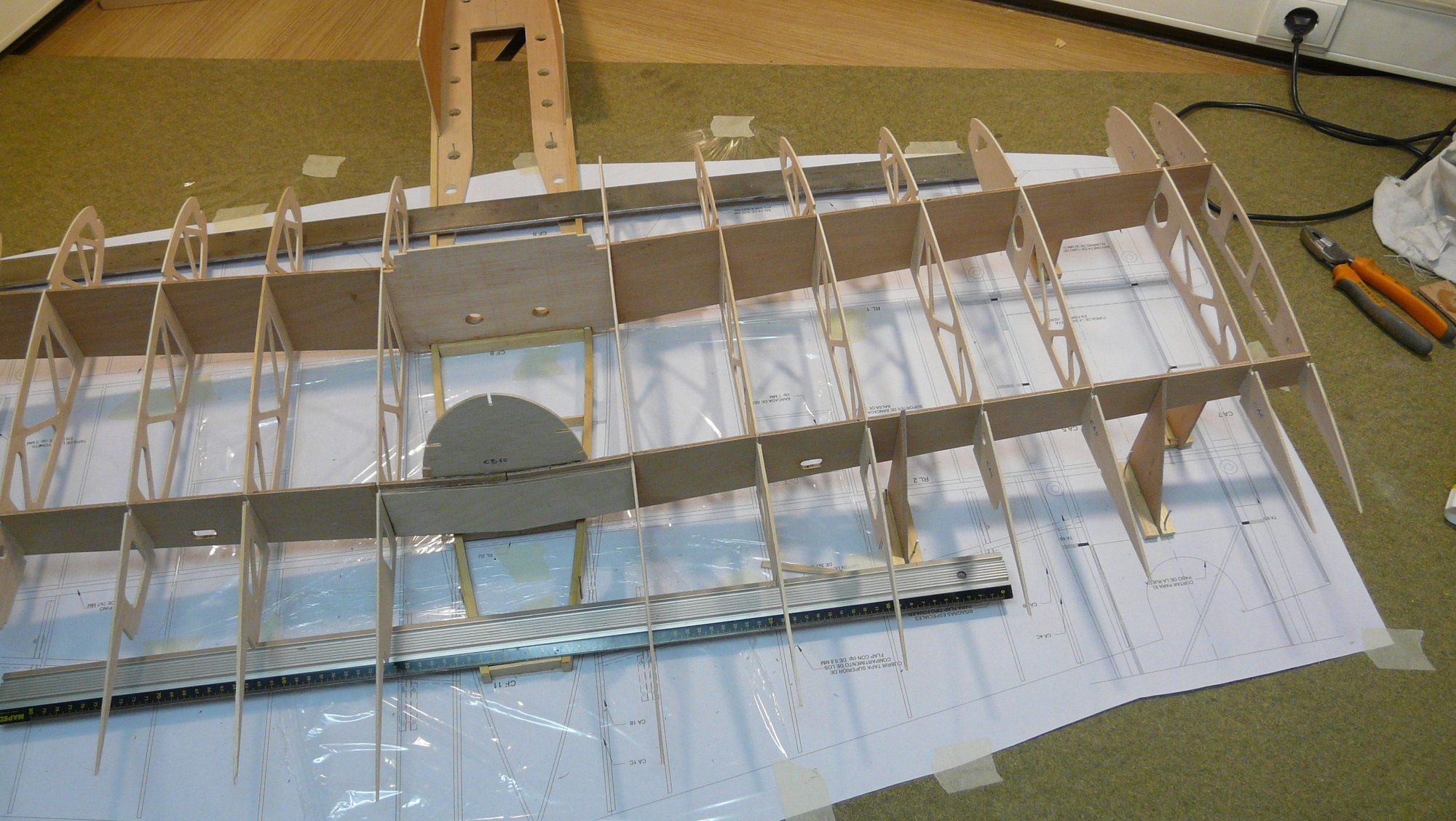
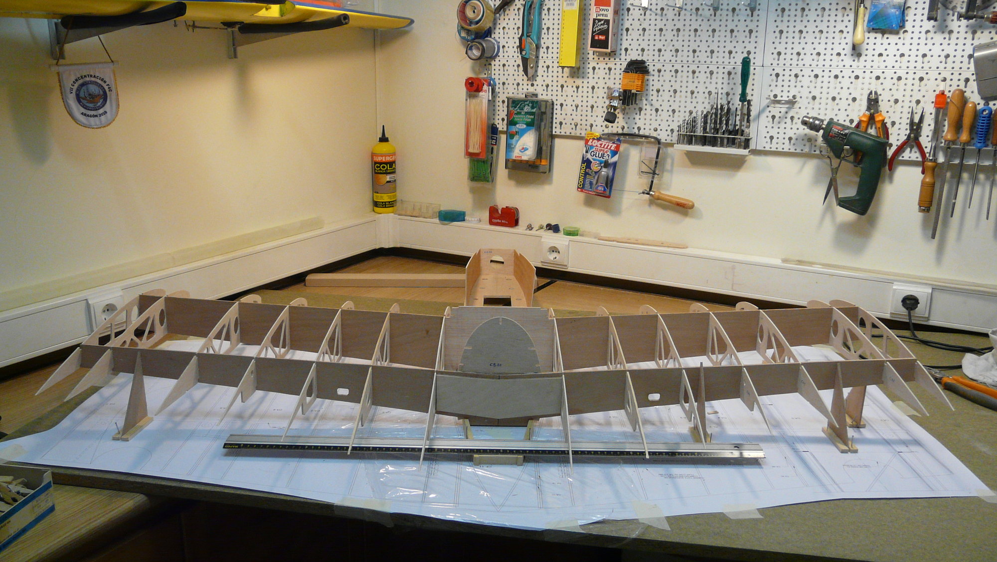
 07-12-2018, 08:42 AM
#18
Thread Starter
Join Date: Oct 2012
Location: ZARAGOZA, SPAIN
Posts: 97
Likes: 0
Received 0 Likes
on
0 Posts
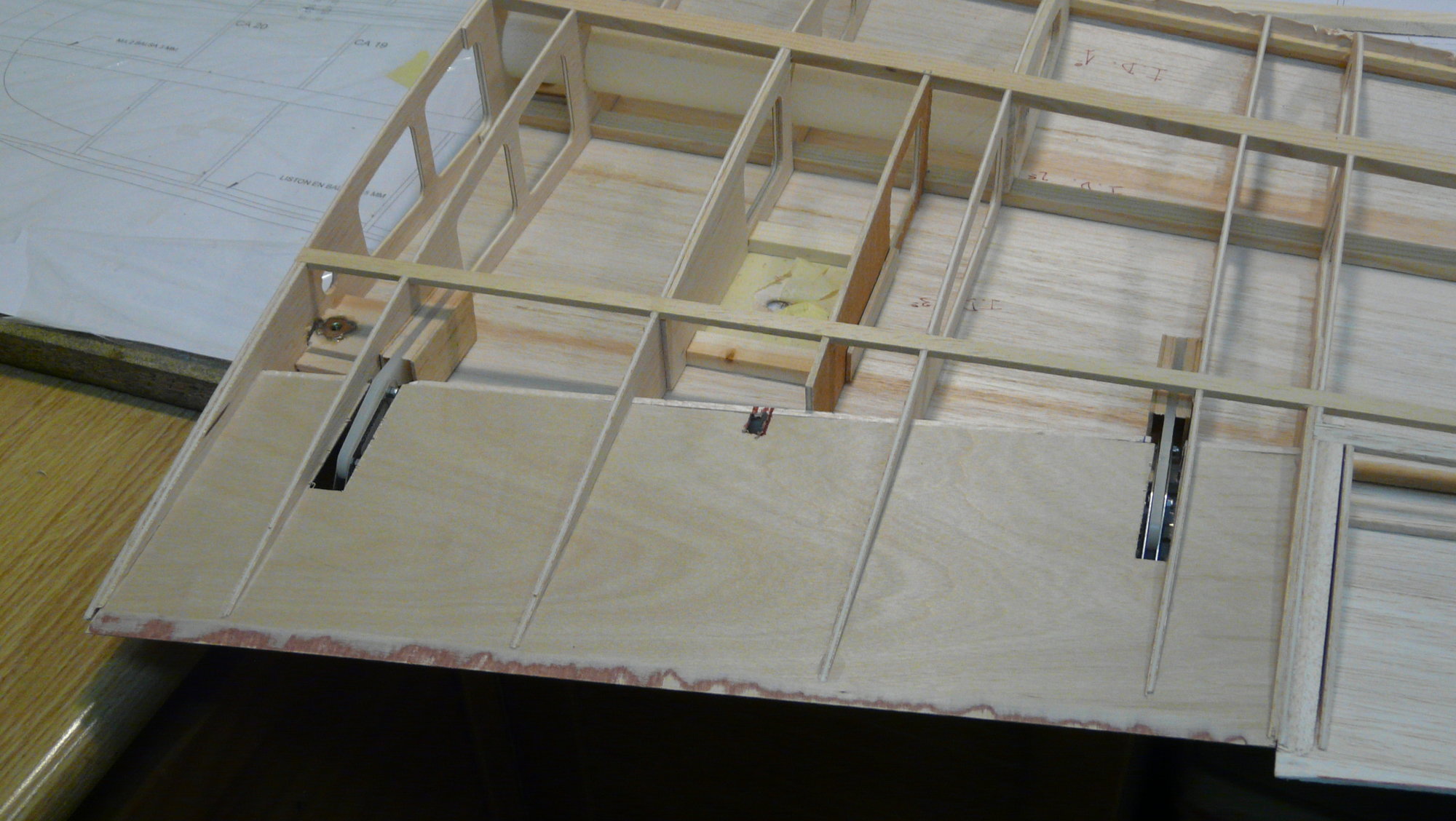
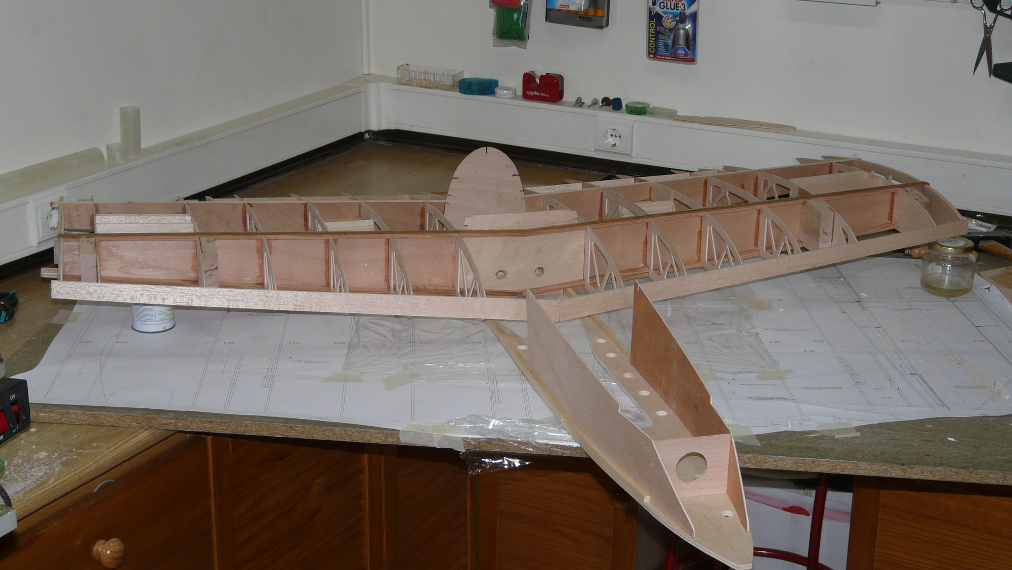
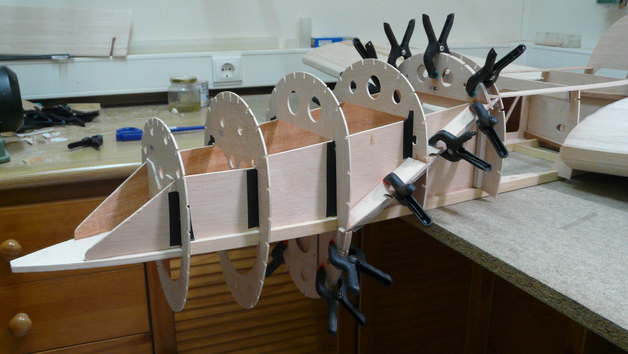
Once the assembly is dry, the main wing spars are glued to the wing beams and ribs (in Oregon pine for the front and Valsaín pine the rear) and secondary (in samba wood). Then, the beech mounting blocks of both fuselages, previously drilled to 6.5 mm, are glued with slow epoxy.
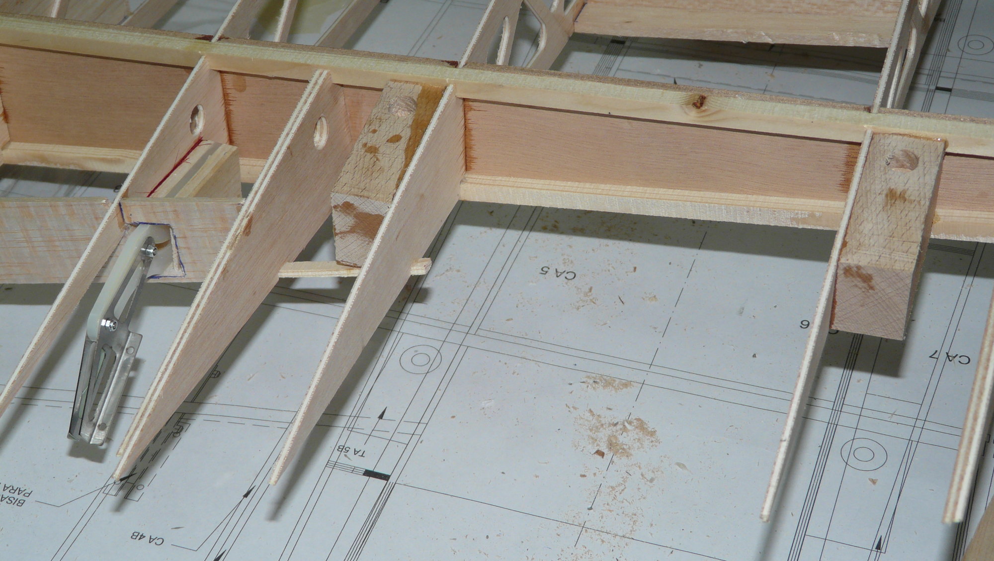
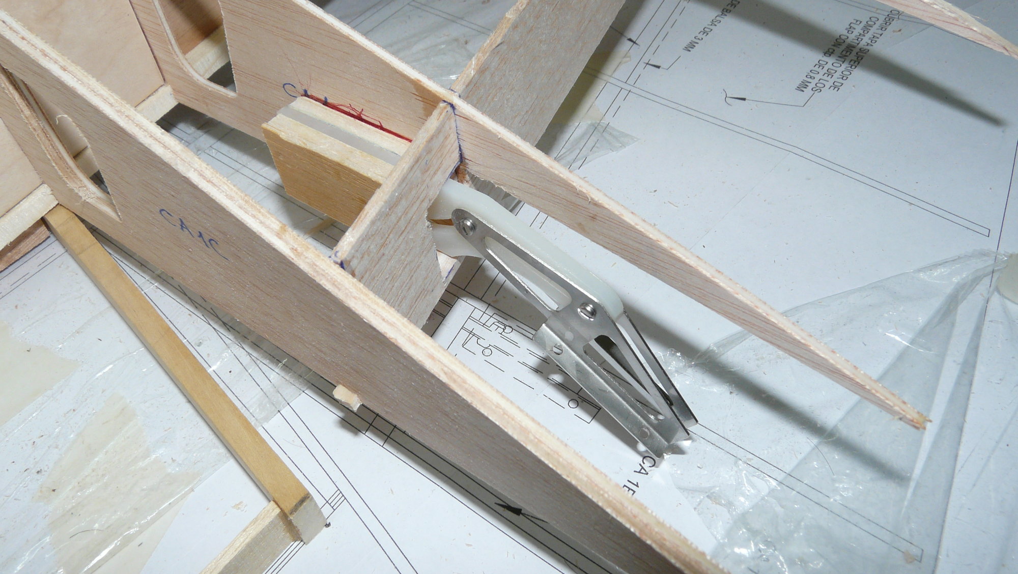
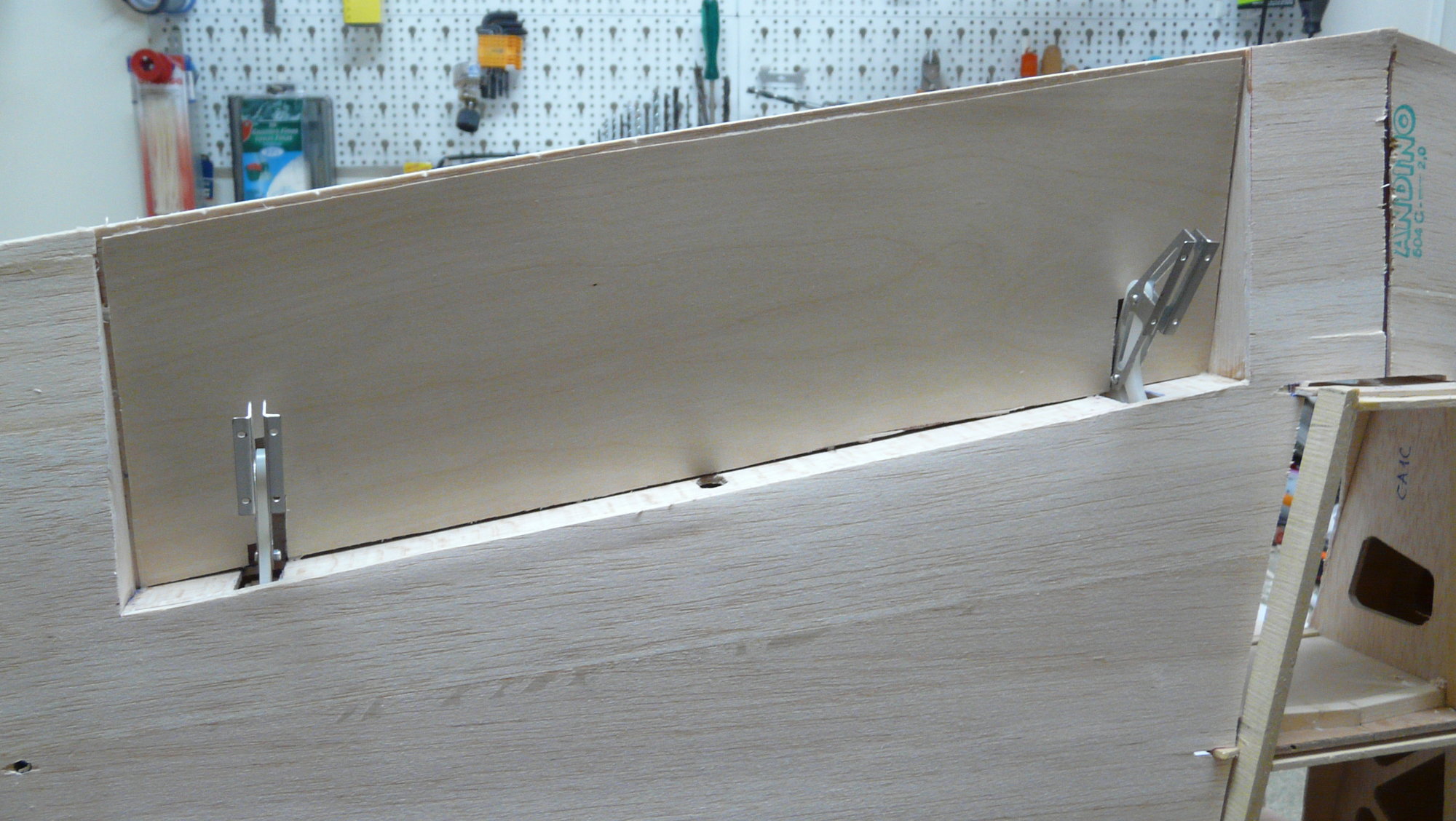
I apologize for not reproduce the original Fowler flap system, so characteristic of this plane, because, to achieve full deflections, it is necessary to use very complex lateral guides and subject to possible breakages that are difficult to access. Instead, I used Fowler flap hinges 1/4 scale from Robart that, while not producing such a wide deflection, perfectly fulfill their purpose and provide a simpler and more robust system. Therefore, now is the time to stick them in position.
The wing mount tube cover is also glued, which we will have made in fiberglass tube over a 32 m aluminum tube with an interior reinforced with solid wood. After that, the top and bottom of the wing are covered, using in each case a single sheet balsa of 2 mm (3/32'') that we will have assembled before


.
I apologize for not reproduce the original Fowler flap system, so characteristic of this plane, because, to achieve full deflections, it is necessary to use very complex lateral guides and subject to possible breakages that are difficult to access. Instead, I used Fowler flap hinges 1/4 scale from Robart that, while not producing such a wide deflection, perfectly fulfill their purpose and provide a simpler and more robust system. Therefore, now is the time to stick them in position.
The wing mount tube cover is also glued, which we will have made in fiberglass tube over a 32 m aluminum tube with an interior reinforced with solid wood. After that, the top and bottom of the wing are covered, using in each case a single sheet balsa of 2 mm (3/32'') that we will have assembled before
.
Last edited by fbielsa; 07-12-2018 at 09:41 AM.
07-13-2018, 10:10 PM
#19
Thread Starter
Join Date: Oct 2012
Location: ZARAGOZA, SPAIN
Posts: 97
Likes: 0
Received 0 Likes
on
0 Posts
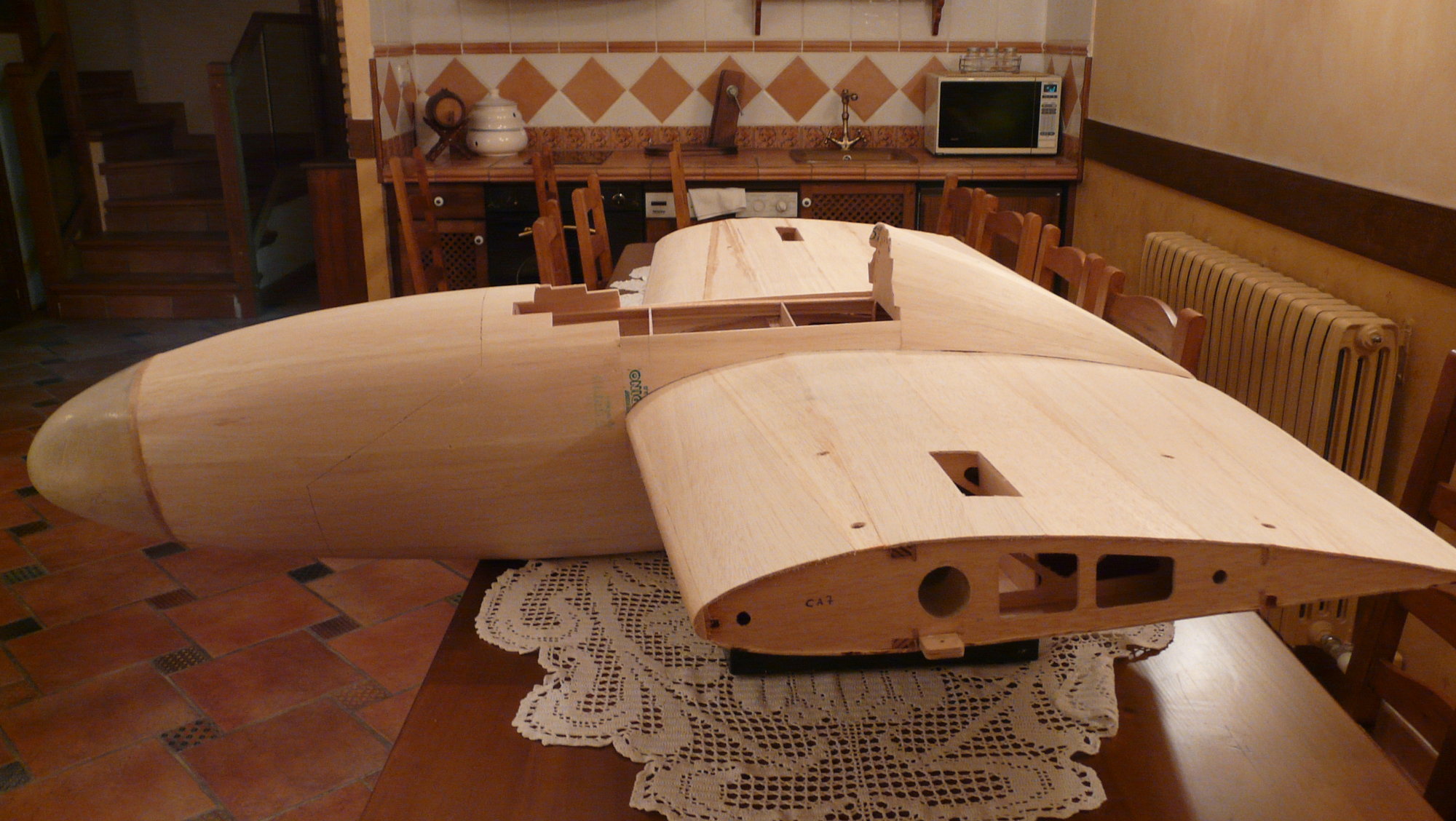
Central section "sheeted". Look both traps at the outer ends of the wings, just for connecting wires from fuses to central section.
Last edited by fbielsa; 07-13-2018 at 10:17 PM.
07-13-2018, 10:16 PM
#20
Thread Starter
Join Date: Oct 2012
Location: ZARAGOZA, SPAIN
Posts: 97
Likes: 0
Received 0 Likes
on
0 Posts
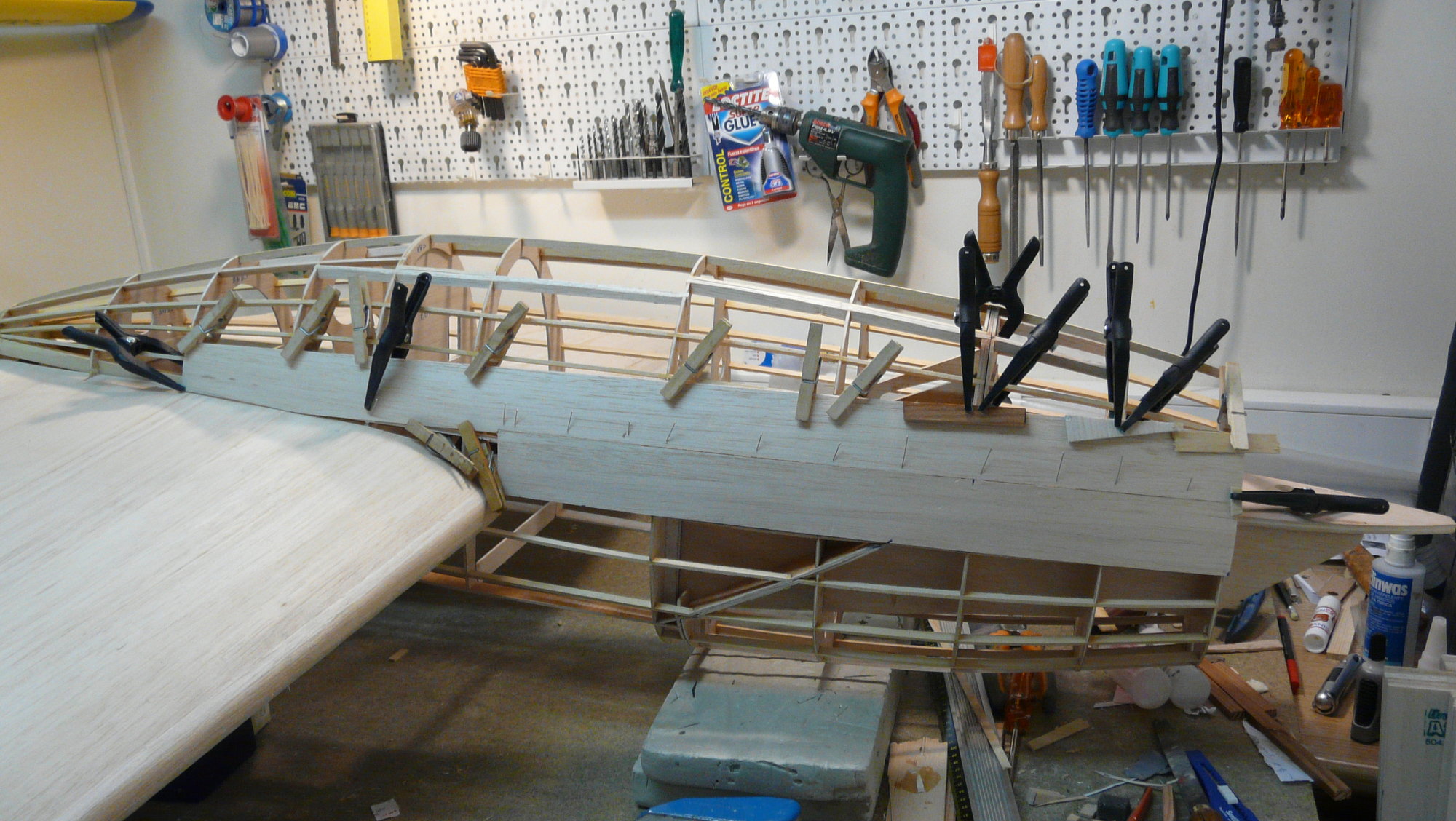
The remaining 3 mm (1/8'') ply formers are glued to the nacelle assembly, first the upper ones and then the bottom ones, but it is not done with the first four, since the nose is removable. All the exterior stringers are made of 3 x 7 mm samba wood.

Last edited by fbielsa; 07-13-2018 at 10:19 PM.
07-17-2018, 10:47 AM
#21
Thread Starter
Join Date: Oct 2012
Location: ZARAGOZA, SPAIN
Posts: 97
Likes: 0
Received 0 Likes
on
0 Posts
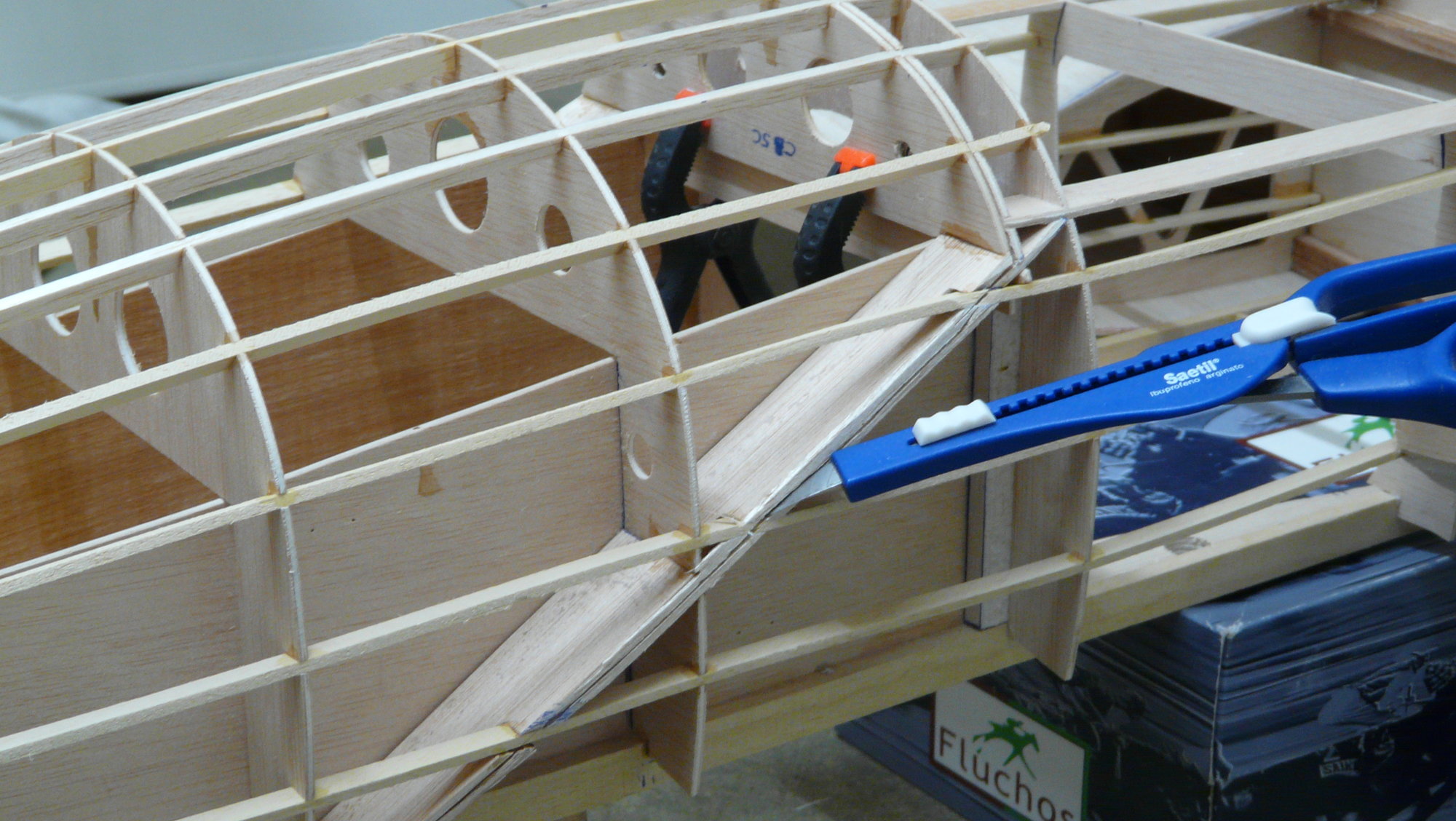
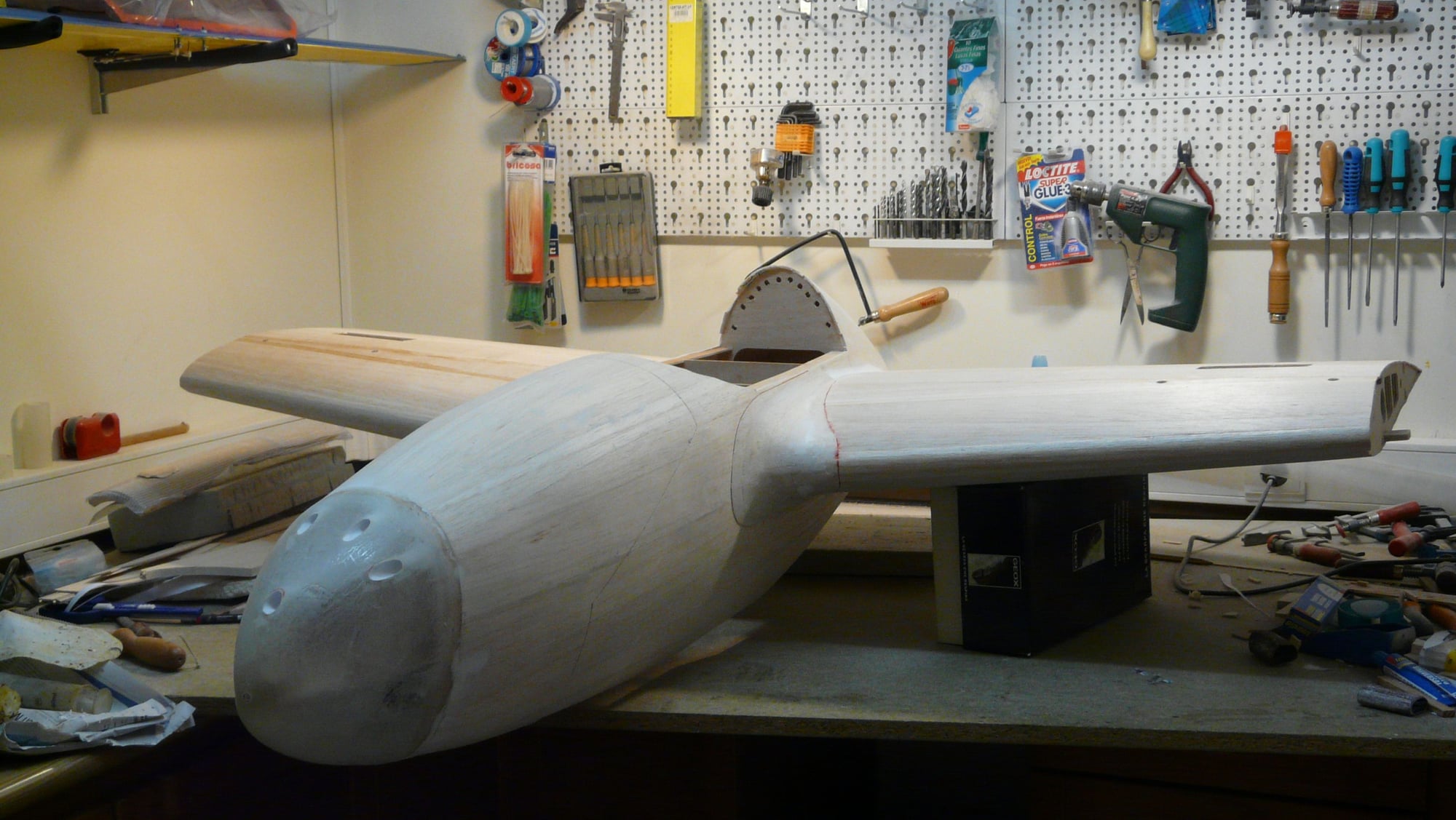
The body of the nacelle is sheeted with 3mm (1/8'') balsa, providing strips in the shape of staves, that is, wider in the central part and narrow at the ends. This aspect has its special difficulty, but it makes it much easier if we glue the widest ones in the less convex areas of the gondola, to add successive narrower staves as we approach the more curved areas.
Once the covering has been completed, it must be cut with a scalpel blade just at the joinct of the double frames that limit the removable nose.
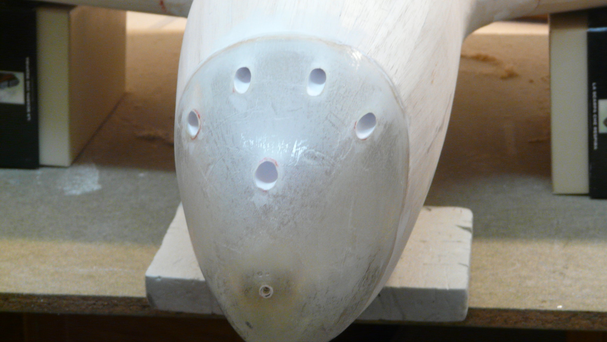
The tip of the nose is molded of resin and fiberglass and added right now, it is masked and the whole coating sanded to a polished surface without reliefs. Now, is the moment to drill the portholes of the four machine guns and the central cannon.
Once the covering has been completed, it must be cut with a scalpel blade just at the joinct of the double frames that limit the removable nose.
The tip of the nose is molded of resin and fiberglass and added right now, it is masked and the whole coating sanded to a polished surface without reliefs. Now, is the moment to drill the portholes of the four machine guns and the central cannon.
Last edited by fbielsa; 07-17-2018 at 10:52 AM.
07-18-2018, 09:48 AM
#22
Thread Starter
Join Date: Oct 2012
Location: ZARAGOZA, SPAIN
Posts: 97
Likes: 0
Received 0 Likes
on
0 Posts

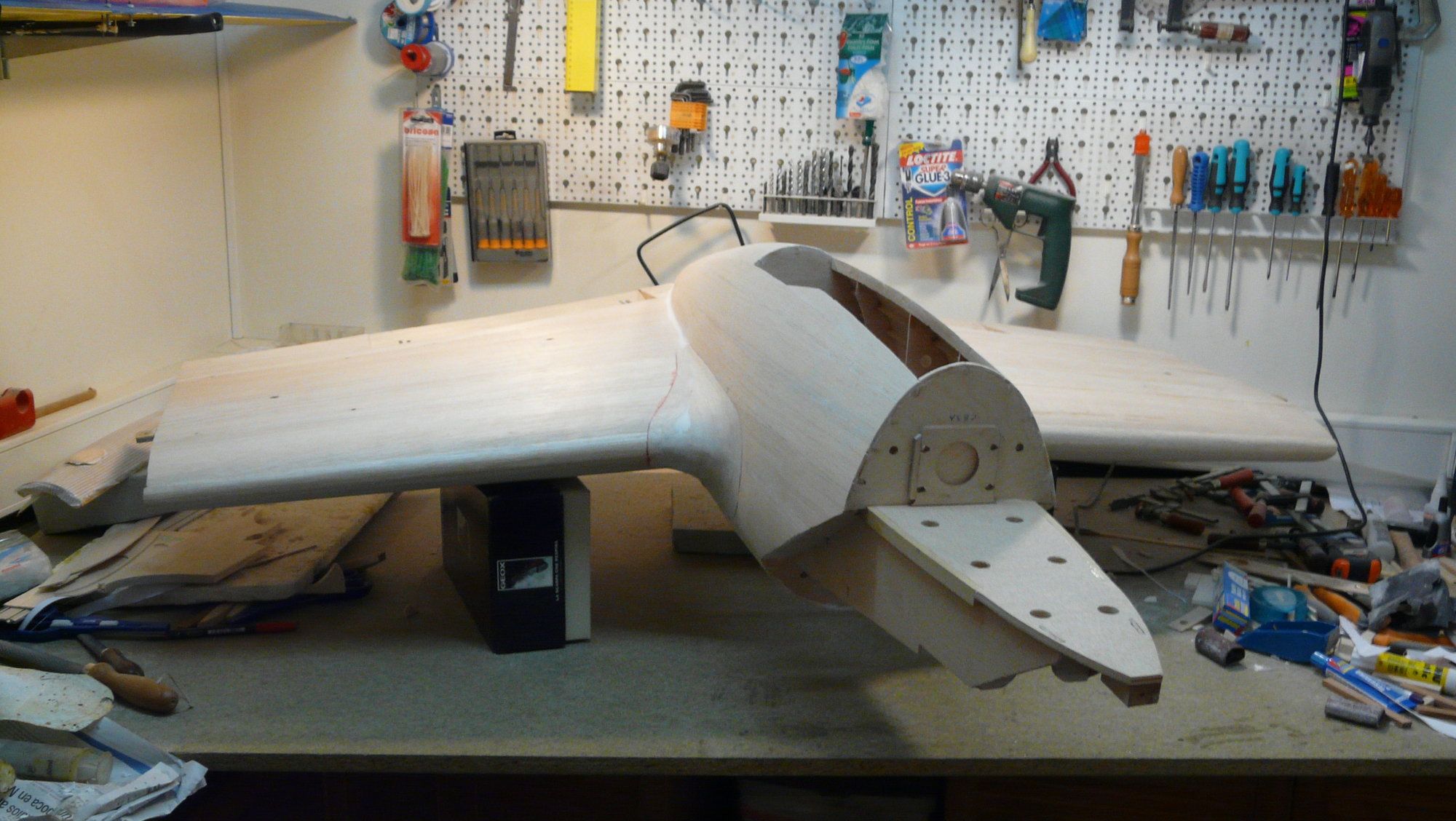
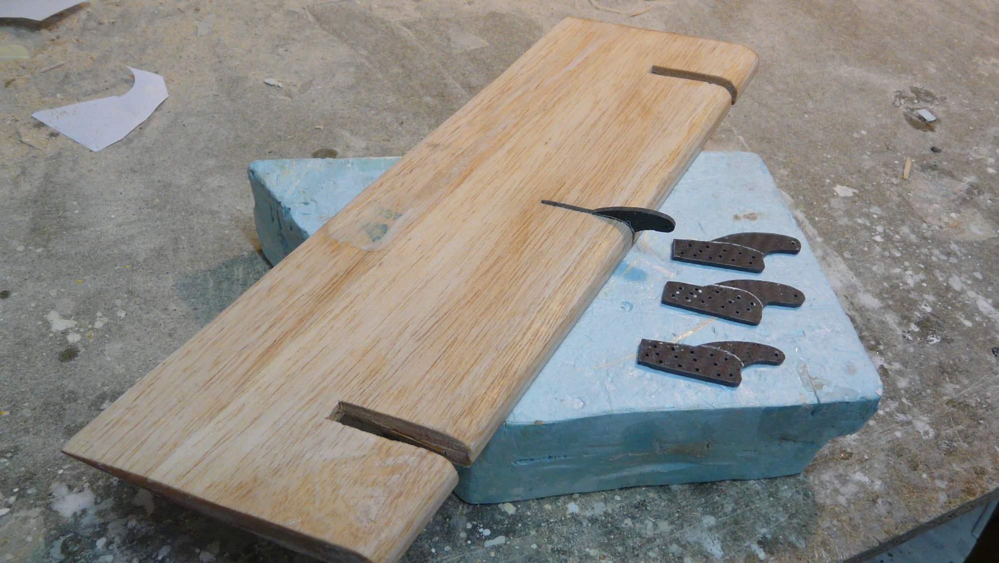
Finally, it is necessary to make the mold of the front gear door using the shape of the gondola for it. Once the final piece of fiber has been obtained, the hollow provided between the frames of the fuselage is cut with a scalpel and the piece is adjusted to its limits. I recommend reinforcing the laminate with carbon strips to get resistance without penalizing the weight, since its length makes it very flexible; In addition, its interior face has been double-walled with little balsa formers, making it very robust and lightweight, allowing the realization of interior details.
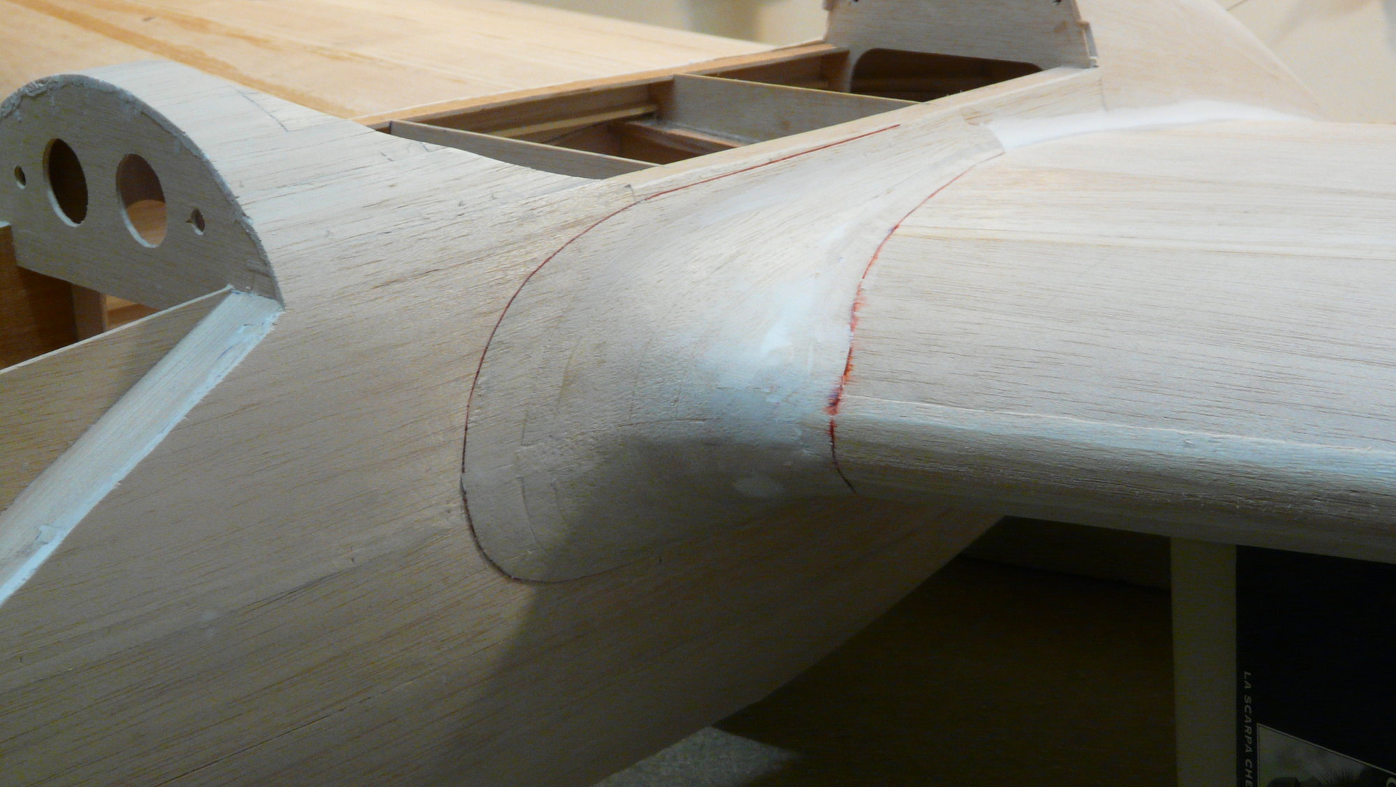
The aerodynamic "kármán" (wing fillet) is obtained on strips of balsa of different thickness, sanded with care to obtain its special shape. The transition of the sides of the gondola with the rest of the wing is made with light mastic. The flaps are carved in solid balsa.
 07-20-2018, 08:50 AM
#24
Thread Starter
Join Date: Oct 2012
Location: ZARAGOZA, SPAIN
Posts: 97
Likes: 0
Received 0 Likes
on
0 Posts
Outer wings
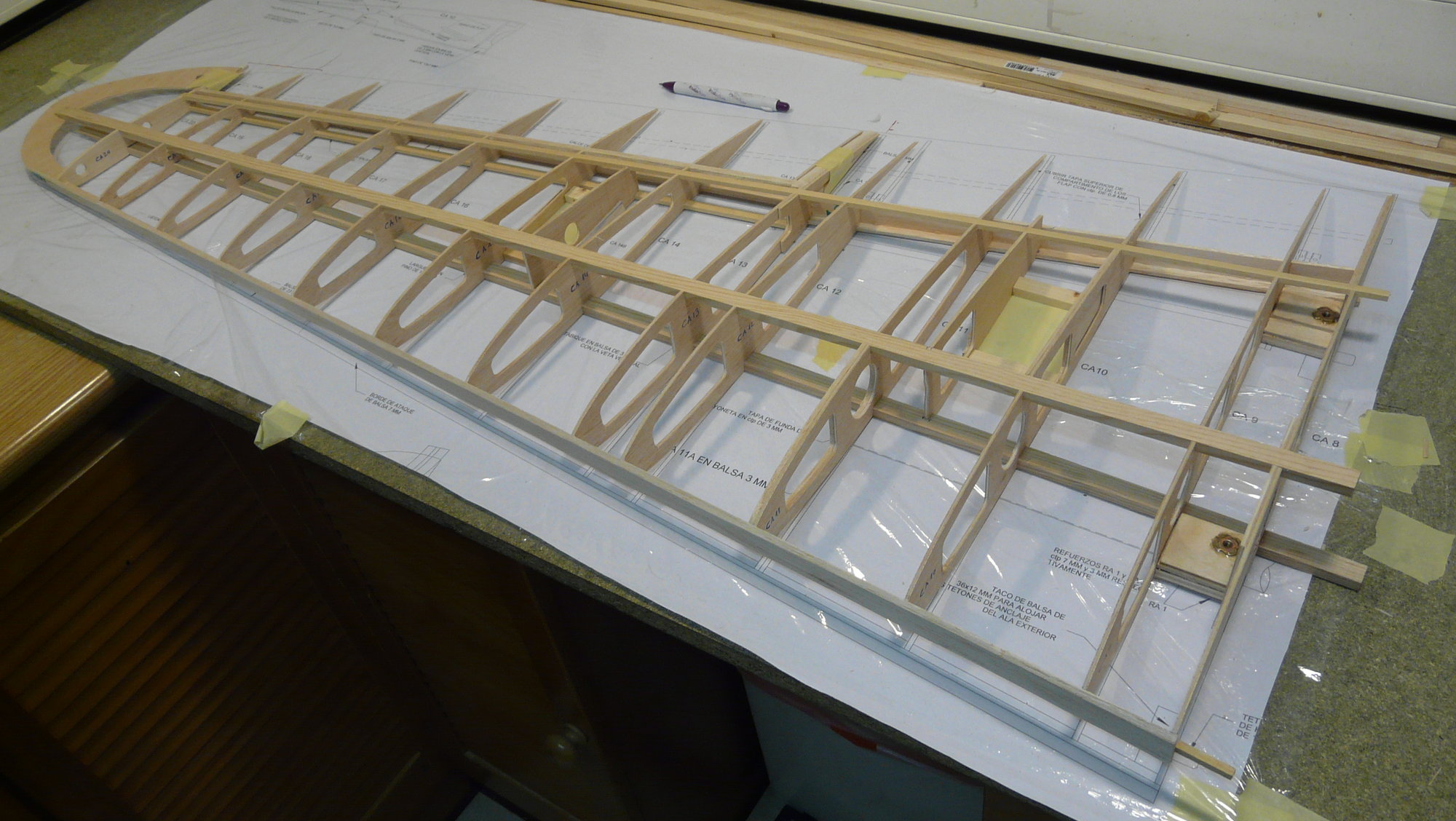
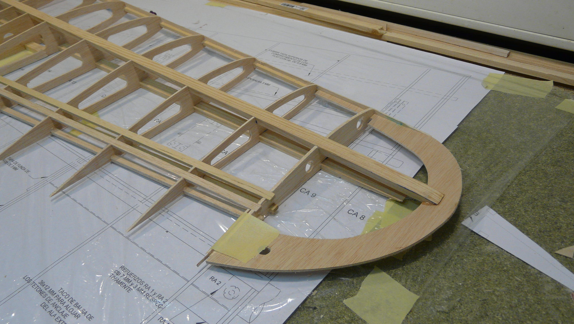
Also in classic structure, to reduce times I advise to build them at the same time over the plan in the traditional way, fitting with a spar wedge at the trailing edge to facilitate the geometric deformation. The profile starts in the proximal section from the mentioned NACA 2414 and ends in the marginal with a NACA 2412.
The main wing spars are made from spruce (Valsaín pine wood) 13 x 7 mm, with balsa reinforcements with vertical vein, secondary in samba wood, ribs in ply 3mm and 2mm balsa bottom sheet.
07-20-2018, 09:00 AM
#25
Thread Starter
Join Date: Oct 2012
Location: ZARAGOZA, SPAIN
Posts: 97
Likes: 0
Received 0 Likes
on
0 Posts
In the same way, once the bottom sheet and the Fowler hinges of the flaps have been glued, it is necessary to glue the tube cover, taking care to do so with the wing mounted on the central section and reviewing its holes in the ribs until the bottom edge fits perfectly. The wings are attached to the central section with one M4 screw and positioned with two hollow aluminum dowels. Finally, the upper surface can be sheeted. The ailerons are cut off from the assembly and hinged with flat hinges at the top. The flaps are carved in solid balsa too.