


MOKI RADIAL Care and Maintenence
 04-07-2021, 03:34 AM
#4576
A few unlearned questions. Did moki radial engines ever run on methanol?
When we're the initial Moki radial models introduced. What serial number sequence did they bear?
Nothing against petrol but the ancillary devices ( ignition and sensors ) required are all unnecessary devices prone to failure not required to burn methanol.
The used one that came up for sale mentioned " early" but does have an ignition system, so petrol seems to be it's fuel requirement.
The company's web presence isint very forthcoming. From my attempts to learn of the company and it's history concerning it's radial engine line have been mostly based in racing single methanol engines as a national competition with Soviet block nations.
Anybody know more and would wish to share?
Thanks to you all. I am learning much about the 250 I have not mounted or run yet. I hope to maiden it later this year.
Thanks in advance!
Aaron-
 04-07-2021, 06:09 AM
#4577

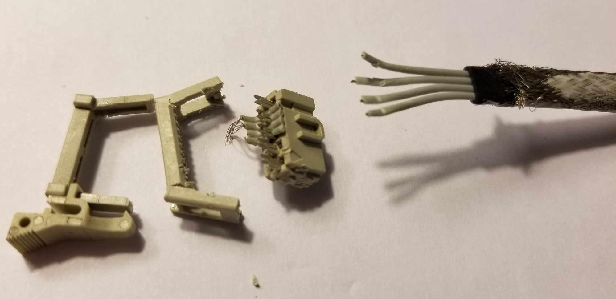
Problem solved, the hall sensor cable was damaged under the shrinkable tube (so invisible). So in fact you can have a partially working Hall sensor, detecting movement and thus get the blue box ignition passing the initialization phase but not working properly (no sparks). I also learned that a 180 blue box would work with the 250 (at least statically) but the hall sensor Iis different
This is a TERRIBLE design. I am exceedingly careful with this engine and after very little time, these wires had broken. It is unfortunate that Moki continues with this design as there is ample room for improvement at very little cost.
For the price of a Moki, we deserve better.
04-07-2021, 07:56 AM
#4578

My Feedback: (2)
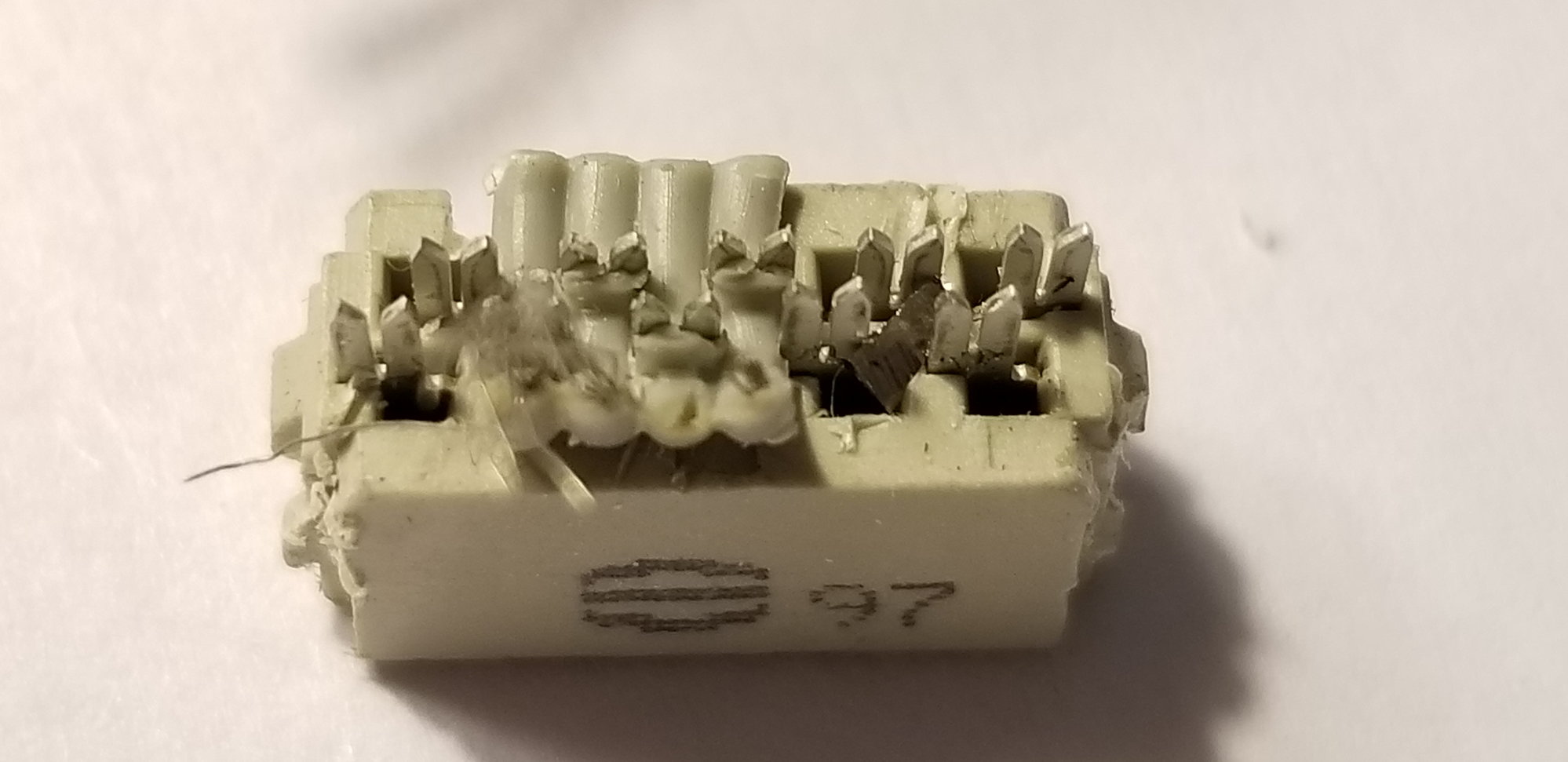
I had the same problem. The Hall Sensor cable wires had broken where the cable bends to meet the connector that plugs into the Blue Ignition box.
This is a TERRIBLE design. I am exceedingly careful with this engine and after very little time, these wires had broken. It is unfortunate that Moki continues with this design as there is ample room for improvement at very little cost.
For the price of a Moki, we deserve better.
This is a TERRIBLE design. I am exceedingly careful with this engine and after very little time, these wires had broken. It is unfortunate that Moki continues with this design as there is ample room for improvement at very little cost.
For the price of a Moki, we deserve better.
 04-13-2021, 12:31 PM
#4579
A few unlearned questions. Did moki radial engines ever run on methanol?
When we're the initial Moki radial models introduced. What serial number sequence did they bear?
Nothing against petrol but the ancillary devices ( ignition and sensors ) required are all unnecessary devices prone to failure not required to burn methanol.
The used one that came up for sale mentioned " early" but does have an ignition system, so petrol seems to be it's fuel requirement.
The company's web presence isint very forthcoming. From my attempts to learn of the company and it's history concerning it's radial engine line have been mostly based in racing single methanol engines as a national competition with Soviet block nations.
Anybody know more and would wish to share?
Thanks to you all. I am learning much about the 250 I have not mounted or run yet. I hope to maiden it later this year.
Thanks in advance!
Aaron-
When we're the initial Moki radial models introduced. What serial number sequence did they bear?
Nothing against petrol but the ancillary devices ( ignition and sensors ) required are all unnecessary devices prone to failure not required to burn methanol.
The used one that came up for sale mentioned " early" but does have an ignition system, so petrol seems to be it's fuel requirement.
The company's web presence isint very forthcoming. From my attempts to learn of the company and it's history concerning it's radial engine line have been mostly based in racing single methanol engines as a national competition with Soviet block nations.
Anybody know more and would wish to share?
Thanks to you all. I am learning much about the 250 I have not mounted or run yet. I hope to maiden it later this year.
Thanks in advance!
Aaron-
All the Moki-Modell designed and manufactured radials serial number sequencing starts with the capacity and the individual engine number, i.e 180XXX, 215XXX, 250XXX.
The glow engine team race and stunt engine production were not made by Moki-Modell, but emanate from the Hungarian Governnment Model Sporting Department which built engines for its own government sponsored fliers back in the Communist era before 1990. It was dissolved and new private company established by Ernst Eberle and his son-in-law, Hans-Dieter Reisert of Airworld started producing range of petrol and methanol large (20-90 cc) model two-strokes, subsequently when we saw that 2 strokes demand was declining, the range of radials were designed by Ernst and developed/sold by Airworld (and myself in the UK) for the past twenty five years in Europe. A couple of organisations have sold them in the US, RC Showcase and more recently Vogelsang Aeroscale.
Trust this clarifies?
Last edited by StuartMackay; 04-13-2021 at 12:35 PM.
The following users liked this post:
Moebius44 (04-13-2021)
04-13-2021, 02:47 PM
#4580
Yes it does Stuart. Thank you for the response and history of the power plant. I was able to gain more insight as well from your web presence. Fascinating history.
Fascinating engine. My wife is Hungarian. We hope to visit Hungary post covid. Definitely like to see that shop!
Gratitude to you Stuart. Thank you for your time.
Cheers
Aaron-
Fascinating engine. My wife is Hungarian. We hope to visit Hungary post covid. Definitely like to see that shop!
Gratitude to you Stuart. Thank you for your time.
Cheers
Aaron-
04-23-2021, 04:34 PM
#4581
My Feedback: (2)
Anyone needing a Moki 250 baffle pattern. The attached files were drawn and scanned to a PDF on legal (8.5" x 14") paper. If you print the files to scale make certain the pattern diameter of the 2 halves equals 13.125" so the baffles will fit the cylinder profiles. If a larger diameter is needed for your cowl, just expand the diameter but keep the original scale for the baffles. I also have the files saved as a JPEG.
Regards - J Tab
Regards - J Tab
Last edited by Jaketab; 04-24-2021 at 06:04 AM.
 05-02-2021, 12:23 AM
#4583
I thought, from some post I read here, that isolating the exhaust ring of my Moki 250 into my Fw190 1/37 was a good idea: not so much air exhaust on this machine, and I did not want to overheat the engine compartment, ...
Well, it turns out that it was probably not such a good idea, ...
It seems no issue in flight: temperatures in the range of 65 to 75 Celsius, taken from the Powerbox 5 cylinders sensor from the top of each cylinder. Raising to 90 to 110 for a few minutes after the engine stops (I guess exhaust is sending back its heat to the cylinder head or sensor).
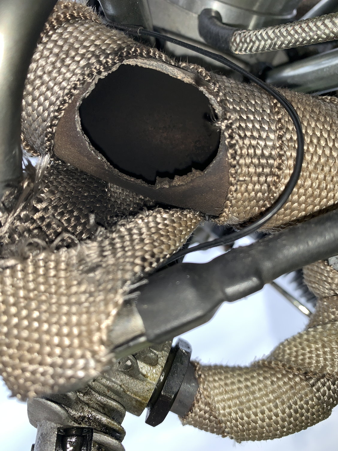
But after a few flights, it broke on the exhaust tube, and when removing the collector ring, I realize it should have been very hot has the little Teflon ring have just burned.
I hope a colleague of mine will be able to repair it using a TIG otherwise, will need to buy a new one, the standard one costs 260 Euro.
Questions:
- does anyone knows about an alternative exhaust ring, Especially one with a single exhaust at the bottom (this way, I would avoid having to add extra tubing for the FW190)
- For those using Moki 250 into an FW 190, how did you manage to cool down this beast (I'm currently having a scale 12 blades turbine and standard engine baffling). I'm afraid that without this heat insulator, it will be very hot inside ...
Thanks for your tips
Well, it turns out that it was probably not such a good idea, ...
It seems no issue in flight: temperatures in the range of 65 to 75 Celsius, taken from the Powerbox 5 cylinders sensor from the top of each cylinder. Raising to 90 to 110 for a few minutes after the engine stops (I guess exhaust is sending back its heat to the cylinder head or sensor).
But after a few flights, it broke on the exhaust tube, and when removing the collector ring, I realize it should have been very hot has the little Teflon ring have just burned.
I hope a colleague of mine will be able to repair it using a TIG otherwise, will need to buy a new one, the standard one costs 260 Euro.
Questions:
- does anyone knows about an alternative exhaust ring, Especially one with a single exhaust at the bottom (this way, I would avoid having to add extra tubing for the FW190)
- For those using Moki 250 into an FW 190, how did you manage to cool down this beast (I'm currently having a scale 12 blades turbine and standard engine baffling). I'm afraid that without this heat insulator, it will be very hot inside ...
Thanks for your tips
05-02-2021, 12:49 AM
#4584

My Feedback: (43)
If your those temps you listed are accurate, those are well within the acceptable range. My top cylinder was running 280�, so I added a louver to the top of the cowl and painted the louver to match the cowl. This dropped me down to 230�
I use these louvers on several birds > Anodized Aluminum Cooling Vents Large (valleyviewrc.com)
I use these louvers on several birds > Anodized Aluminum Cooling Vents Large (valleyviewrc.com)
The following users liked this post:
jcsotto (05-02-2021)
05-02-2021, 01:44 AM
#4585
Hello Ultimate, did you find a solution to your problem ?
My bet is that you have a hydraulic lock as you suggested. The trick with the Moki is that when you turn around the engine, some liquid can be stored in the crankcase and then suddenly moving into a cylinder (generally the lower one) when you reach certain position.
It may take a while to evacuate all liquid that you pour into the engine. The safest way and also good for check and cleanup (there was some black grease in mine) would be to remove completely the engine back cover. For this, you have to remove the carburetor, engine mount, intake tubes, and electric coil housing. Not a big deal, just take some time. Be careful about the position of each element to put them back into the same position.
05-02-2021, 05:42 AM
#4586
I thought, from some post I read here, that isolating the exhaust ring of my Moki 250 into my Fw190 1/37 was a good idea: not so much air exhaust on this machine, and I did not want to overheat the engine compartment, ...
Well, it turns out that it was probably not such a good idea, ...
It seems no issue in flight: temperatures in the range of 65 to 75 Celsius, taken from the Powerbox 5 cylinders sensor from the top of each cylinder. Raising to 90 to 110 for a few minutes after the engine stops (I guess exhaust is sending back its heat to the cylinder head or sensor).
But after a few flights, it broke on the exhaust tube, and when removing the collector ring, I realize it should have been very hot has the little Teflon ring have just burned.
I hope a colleague of mine will be able to repair it using a TIG otherwise, will need to buy a new one, the standard one costs 260 Euro.
Questions:
- does anyone knows about an alternative exhaust ring, Especially one with a single exhaust at the bottom (this way, I would avoid having to add extra tubing for the FW190)
- For those using Moki 250 into an FW 190, how did you manage to cool down this beast (I'm currently having a scale 12 blades turbine and standard engine baffling). I'm afraid that without this heat insulator, it will be very hot inside ...
Thanks for your tips
They will position the outlets wherever you need them to order.
Ringsammler / Ringschalld�mpfer f�r Sternmotoren - Zimmermann Edelstahl Abgassysteme (zimmermannschalldaempfer.de)
I would try my best to get the in-cowl temps reduced by effective cooling as you do not want you carburettor breathing hot air as this will result in a thermal run away and seizure of the engine!
Remember air outlet needs to be twice the inlet area!!!!!
Your hole looks like a brittle/fatigue fracture, is this where one of the exhaust outlets was?
Last edited by StuartMackay; 05-02-2021 at 05:44 AM.
The following users liked this post:
jcsotto (05-02-2021)
05-02-2021, 09:32 AM
#4587
The stainless collector ring available from Zimmermann in Germany will have a much higher melting temperature than the standard aluminium ones.
They will position the outlets wherever you need them to order.
Ringsammler / Ringschalld�mpfer f�r Sternmotoren - Zimmermann Edelstahl Abgassysteme (zimmermannschalldaempfer.de)
I would try my best to get the in-cowl temps reduced by effective cooling as you do not want you carburettor breathing hot air as this will result in a thermal run away and seizure of the engine!
Remember air outlet needs to be twice the inlet area!!!!!
Your hole looks like a brittle/fatigue fracture, is this where one of the exhaust outlets was?
Question is. Will the motor breathe right without a larger supply of incoming air with these restrictions and trapped heat between the ring and airframe? Or will the heat and restrictions be overwhelming to correct cooling?
The motor will be un cowled on this PT 17 biplane. I had not planned to baffle between cylinders initially.
Thank you for your thoughts in advance.
Aaron-
05-02-2021, 01:48 PM
#4588
Interesting post. I am setting up a 250 in a Stearman 1/3 scale. The carb inlet will be close to the firewall. A 3/4 inch hardwood spacer ring will be necessary to mount the engine which will provide clearance but will also further restrict incoming flow. The simple solution obviously is a clearance hole in the firewall and drawing air from the fuselage. Or creating a intake tube to ram force air in from a scoop under the cowl. ( Certainly not scale for the airframe) neither system would be bringing in above ambient air temp supplies.
Question is. Will the motor breathe right without a larger supply of incoming air with these restrictions and trapped heat between the ring and airframe? Or will the heat and restrictions be overwhelming to correct cooling?
The motor will be un cowled on this PT 17 biplane. I had not planned to baffle between cylinders initially.
Thank you for your thoughts in advance.
Aaron-
Gates Flexible Air Duct Hose - 25mm - 1 Meter 5412571009880 | eBay
If it uncowled, you have nothing to worry about!
Last edited by StuartMackay; 05-02-2021 at 01:50 PM.
The following users liked this post:
jcsotto (05-02-2021)
05-02-2021, 11:22 PM
#4589
Thanks Stuart, nice product but not cheap. I'll have finally a friend of mine preparing it with TIG but Iif I break one a again we surely look at them.
Yes, this is on the exhaust outlet, fatigue due to the weight of the added extensions that were "free" and a bit long (15cm) and a bit heavy
Yes, this is on the exhaust outlet, fatigue due to the weight of the added extensions that were "free" and a bit long (15cm) and a bit heavy
05-02-2021, 11:37 PM
#4590
Guys, I need to build a test stand to safely run my MOKI-215. Can anyone post a photo or two of their successful mounts? I have a large plywood mount that works for my 100cc to 150cc twin cylinder gas engines, but the exhaust of the MOKI is right on the 12" X 12" vertical mount. I guess I could make a few plywood donuts to space the engine out away from the plywood plate? Thoughts?
Thanks,
Larry
Thanks,
Larry
10 years ago when I started my Phoenix-Project with the powerful V4 engine, I was tired of reinforcing my old wooden structure test bench. It fell apart, more or less.
I was thinking about something as versatile as possible. A friend had a lot of these aluminum profile bars, and so I thought this is it.
I did underestimate ( as so often) the work and effort, but after a while it was ready. Of course the test bench underwent some improvements over the years, oil pressure dial, RPM and temperature measuring was adapted, adjustable
voltage for Ignition and electrical fuel pump,
more adaptor plates for many different engines were build, from an OS GT 33 ( exhaus tuning) to all Mokis from 150 - 180 -250 -300 - 400, Roto 130 inline, the Phoenix with and without gear reduction dribve, whatever was necessary.
As we went to 2 exibitions with the V4, a cage for the prop was mandatory. And- if you have a long term break in- it is also a good idea to use the cage. An accident with such a big prop is something I do not want to imagine.
For a quick test, it is not installed.
Engines like Mokis are mounted with the help of a strong plywood adaptor plate, others are easier installed directly ( metal stand offs or something like that)
I agree it is not suitable for a test every other year, but in my case I am happy to own this one.
It weighs roughly 100 kilograms, and with the V4 and myself standing on the frame (adding to over 200 kilogramm with the engine and me) , it really did accelerate ( horrible steering with the trolley cart wheels ) :-)
Last edited by Detlef Kunkel; 05-02-2021 at 11:48 PM.
05-16-2021, 02:38 PM
#4591
Hello all,
i need help because i am totally confused. I just tried to adjust the valves' clearance for the first time on my new Moki 180. After i did the whole round of setting up then i rechecked and i noticed that all the clearances were different from what i just did.
The way i did it is the way Dr. G described on one of his videos. Start from number 1. Find the point where both valves are moving, then turn 360 degrees and both valves are closed. Then you adjust.
After several trials and turns i realized that if i do a complete turn of the cylinders ( the prop is turned 5 times) i end up to the excaust valve clearance zero and the intake gap bigger, but if i turn again a circle which means 5 turns of the prop then i end up to the initial gaps i adjusted.
This does not make any sense to me unless i miss something.
Can you please help me understand? Could there be any reason where the valve clearance differ?
Thanks in advance,
Lawrence
05-16-2021, 04:53 PM
#4592
My Feedback: (2)
Someone else may be able to explain better, but I'll try. One the Moki 5 cylinder radial engine there are 4 cam lobes. The cam ring or gear has 2 cams for the intake valves and 2 for the exhaust valves. The cams for intake and exhaust are 180 degrees apart. It takes 4 revolutions of the prop to make the cam ring turn 360 degrees. When you adjust cylinder #1 and the valves clearance is perfect. Then rotate the prop 2 times to the same position and the clearance may be slightly different. The cam rockers will be resting on the cam ring 180 degrees from the first valve adjustment. The clearance difference is due to tolerance on the cam ring that may be slightly different. Just make certain that the tightest valve gap is not too close. A slight difference will not hurt long as the difference is not too great or too close.
The following users liked this post:
RichardGee (05-16-2021)
05-16-2021, 09:35 PM
#4593
Someone else may be able to explain better, but I'll try. One the Moki 5 cylinder radial engine there are 4 cam lobes. The cam ring or gear has 2 cams for the intake valves and 2 for the exhaust valves. The cams for intake and exhaust are 180 degrees apart. It takes 4 revolutions of the prop to make the cam ring turn 360 degrees. When you adjust cylinder #1 and the valves clearance is perfect. Then rotate the prop 2 times to the same position and the clearance may be slightly different. The cam rockers will be resting on the cam ring 180 degrees from the first valve adjustment. The clearance difference is due to tolerance on the cam ring that may be slightly different. Just make certain that the tightest valve gap is not too close. A slight difference will not hurt long as the difference is not too great or too close.
Hi Jake,
perfectly explained .
Lawrence, do you turn & check the pos of the crankshaft with a 2-blade prop? I would recommend that.
Once you have the TDC, you can continue with every second coming cylinder.
Important like Jake said is to double check each adjustment exactly 2 full revolutions later ( the "other side" of the cam drum). The smallest Gap is what counts for minimum clearence. Dont "avereage"
Good luck
Last edited by Detlef Kunkel; 05-16-2021 at 09:38 PM.
The following users liked this post:
Maxam (05-17-2021)
05-17-2021, 04:16 AM
#4594
My Feedback: (62)
Detlef, Nice to see you posting here on the Moki forum! I believe I told you I acquired a Moki 257. A fine running engine! I am building a Schlundt 1-2.2 Fly Baby for this engine. This engine has much less mid throttle richness so it "invites" you to run at low throttle which will be ideal for this plane. I once had an older Moki 215 that had a pretty far out of concentric cam ring. Like you and Jaketab said, adjust for the tightest cam so the valves always close. The engine ran well. -Tom
05-20-2021, 01:01 PM
#4596

I've flown Moki's for quite a while. Currently own 3 250's. Bought an air world FW190 that was half done. Has an older 250 on it. Person who I bought it from knows what he is doing... said he had it running well. Plane is painted, ready to go, started the motor... starts and idles fine, great power... over heats... like white smoke coming out of all the valves overheats.... Fatten needles. I can get it to run without overheating, but won't go over 2600 RPM. Threw spare 250 on with same fuel set-up, same needle settings (actually same carb)-this one has turbulator and if I used my non-turbulator Moki, would have had to move servos... got it running like a top, zero overheating, just under 3600 rpm... Problem is.... there is a very small difference in length of the two motors and the valves hit the cowl with the second motor in Arrrghhhhh. So, I have to get this first one running. The only thing I have not checked is the valves, doing that hopefully this weekend. Aside from the valves being way off, any other ideas???
Thanks
Thanks
05-20-2021, 11:57 PM
#4597
I've flown Moki's for quite a while. Currently own 3 250's. Bought an air world FW190 that was half done. Has an older 250 on it. Person who I bought it from knows what he is doing... said he had it running well. Plane is painted, ready to go, started the motor... starts and idles fine, great power... over heats... like white smoke coming out of all the valves overheats.... Fatten needles. I can get it to run without overheating, but won't go over 2600 RPM. Threw spare 250 on with same fuel set-up, same needle settings (actually same carb)-this one has turbulator and if I used my non-turbulator Moki, would have had to move servos... got it running like a top, zero overheating, just under 3600 rpm... Problem is.... there is a very small difference in length of the two motors and the valves hit the cowl with the second motor in Arrrghhhhh. So, I have to get this first one running. The only thing I have not checked is the valves, doing that hopefully this weekend. Aside from the valves being way off, any other ideas???
Thanks
Thanks
If this is so - simply change the rockers if you like.
06-11-2021, 08:19 AM
#4598
Join Date: Jan 2016
Location: Napoli, Italy
Posts: 28
Likes: 0
Received 0 Likes
on
0 Posts
Hi guys, just got my s150; it is my frist MOKI!
Some questions to you experts on this matter.
1)I know the s150 is discontinued and some spares for it are available on Aeroscale website and Airworld.
Just as a generic info, I would like to know if Moki still manufactures spares for the s150 or they just have a stock (...read this as "it is better buy some spares for this engine now...?").
2)I'm going to run this s150 with a 4blades prop on a 93" P47; what is the best 4blades for this engine you guys tested?
3)Furthermore, I was looking at Ramoser-Varioprop propellers; anybody have experience with this prop, can provide some feedback, specially if for the s150 it is better to use the 25f or 32i (as I think) kind?
Rgds
06-14-2021, 09:51 AM
#4599
My Feedback: (6)
Join Date: Mar 2005
Location: monterrey nuevo leon, MEXICO
Posts: 151
Likes: 0
Received 1 Like
on
1 Post
hi guys, I have a very old moki 250. I need someone to give it a MAYOR OVER H. a complete service to it.
julian is not on the motor business any more, gotz vogelsang are out of the office until 21 of june. who can give a complete service to it in USA ?
thanks for your time guys.
julian is not on the motor business any more, gotz vogelsang are out of the office until 21 of june. who can give a complete service to it in USA ?
thanks for your time guys.
Last edited by bucho; 06-14-2021 at 12:32 PM.
06-17-2021, 03:19 PM
#4600
My Feedback: (2)
Need help with my 2 year old Moki 250. The blue box ignition will not arm. On top of the box there are 2 small green LED lights. Upon powering up the blue box (8 volts), I get one solid green and the other is flashing about once per second. This appears to be normal showing there is power to the box but that it has not armed itself because the prop has not been rotated.
Now, when I rotate or flip the prop there is no change in the blinking sequence as there should be. The second light should blink indicating when a cylinder is to fire and that the ignition is armed.
Next, I connected an old spare Top Hat ignition. No dice. The first light powers green but the second green light does not indicate when the internal magnets pass over the pick-up sensor when the prop is rotated.
Two connections come into play here. I call it the round microphone cable that connects the coils to the ignition box. I’ve inspected the connections on this cable and all look good. The other cable is the flat shielded data cable that connects the pick up over the front cam ring magnets with the ignition box. I am hoping that the flat shielded cable may be bad as opposed to replacing the ignition.
In fair disclosure, the engine was involved in a crash last season, but the plane caught most of the damage. The engine was bench tested last season after the crash. It was run successfully on the bench 3 weeks ago. This problem first surfaced last fall when I bench ran the engine, but securing the connector to the ignition box with tie wraps fixed the problem.
Question 1 – could the sensor pick up on the flat cable become demagnetized? I am not certain whether or not it is magnetized to begin with ?
Question 2 – are there magnets within the cam ring and could something have become dislodged internally?
Help or suggestions please.
Regards from a 2 Moki Radial Engine Owner,
Thanks - J Tab