


New Era III from RCM Plans
 08-28-2018, 05:23 AM
#76

Thread Starter
Just when I thought that I am on the home run, I found out (surprise....) that this is not an ARF...
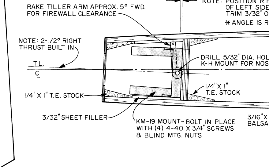
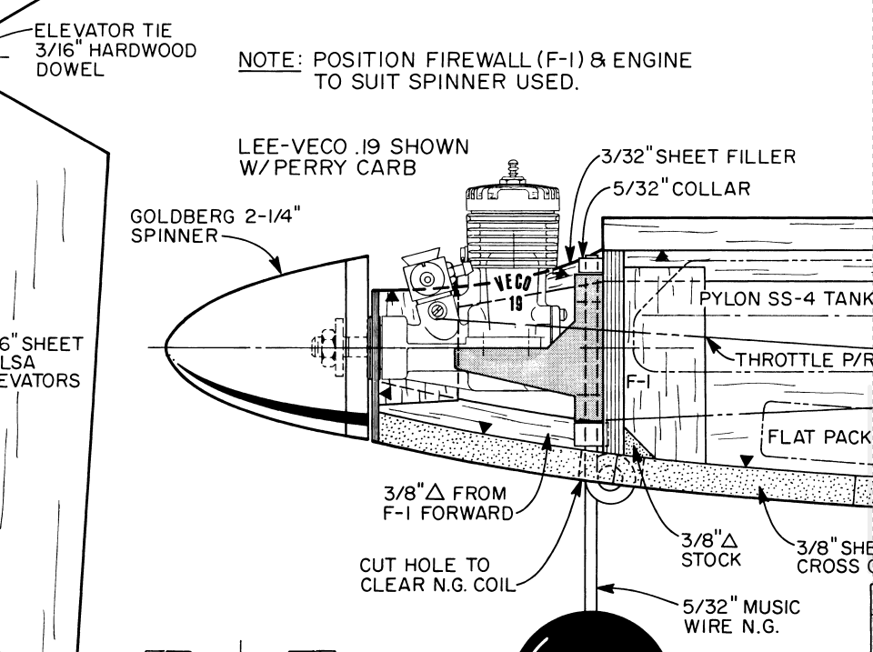
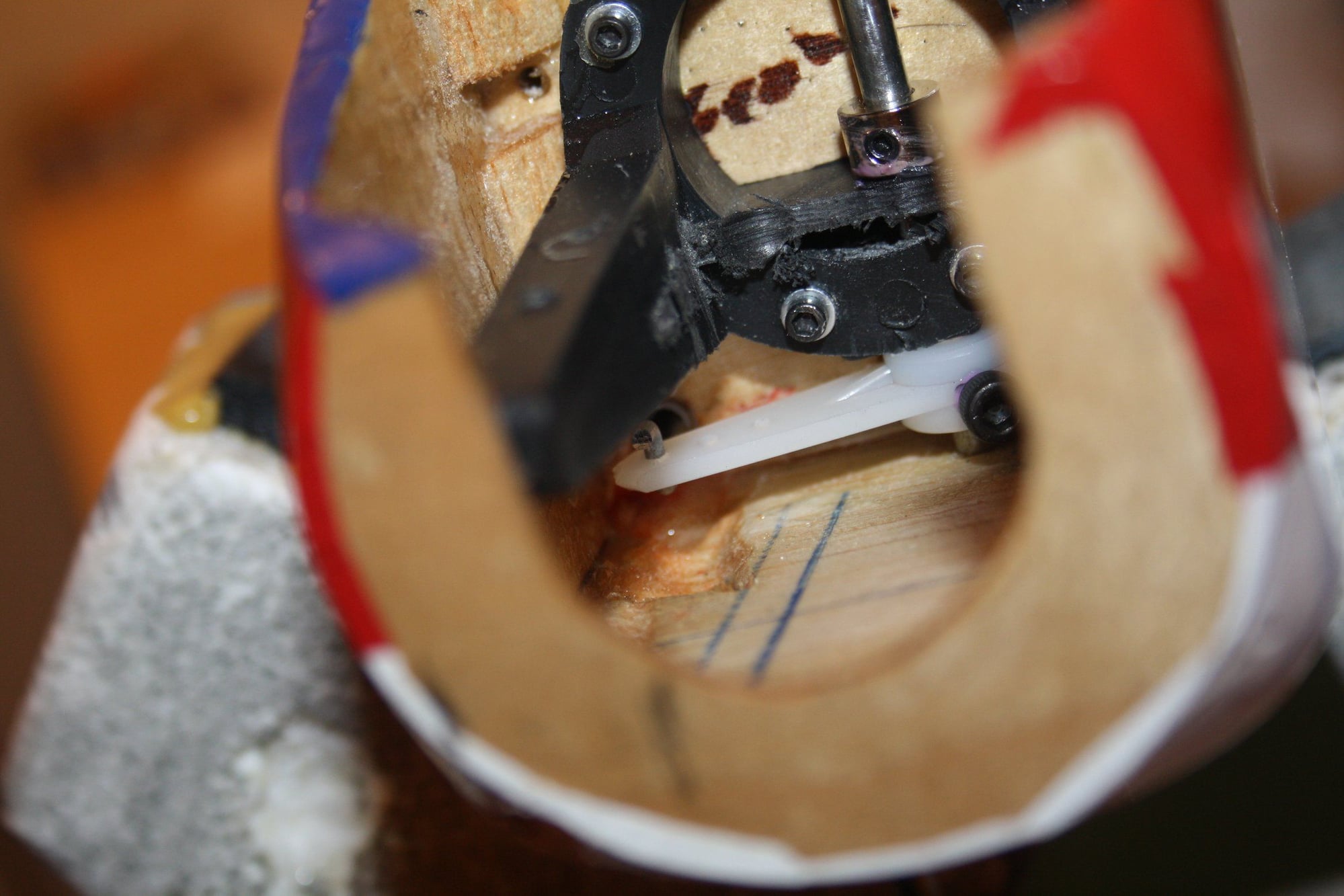
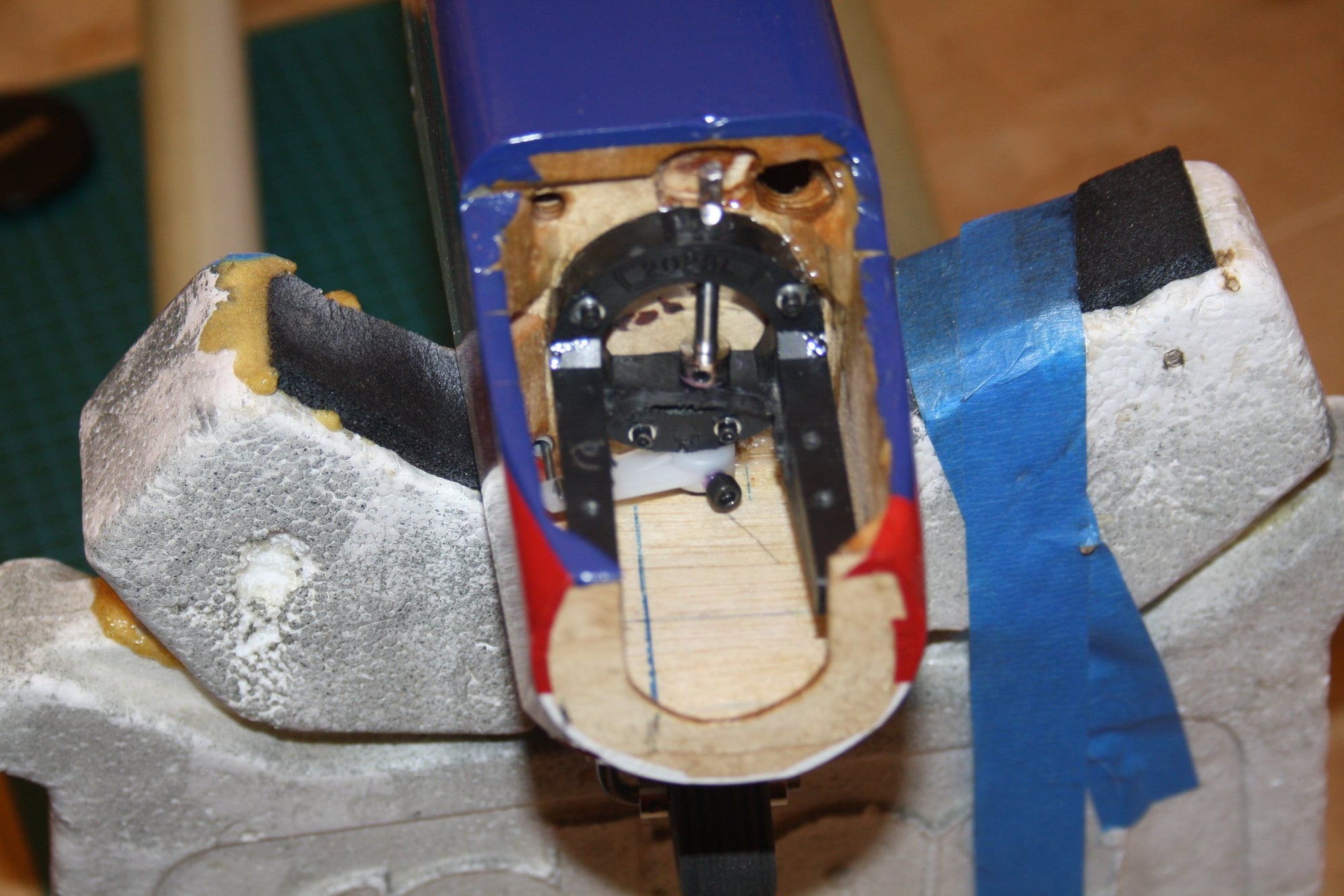
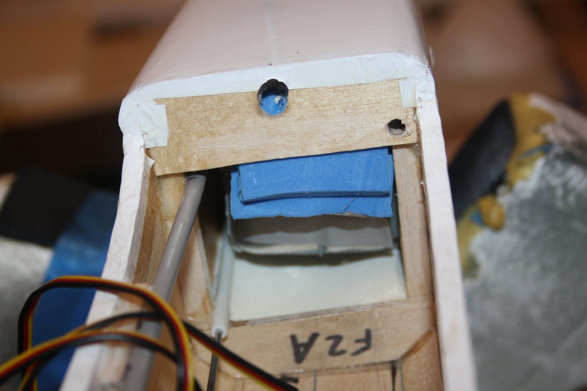
I do not think that the steering for the New Era III was actually possible as "designed". The plans show the horn in both the top and side view, as being under the firewall.
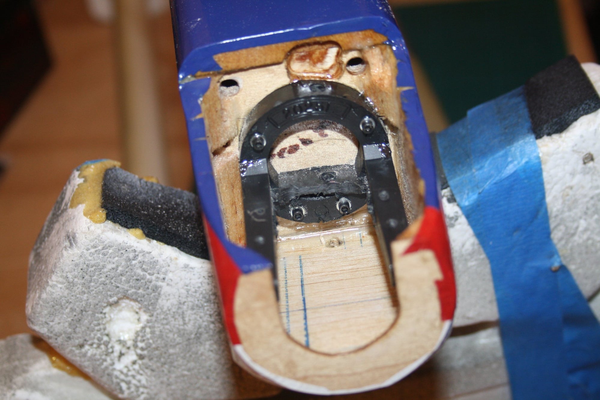
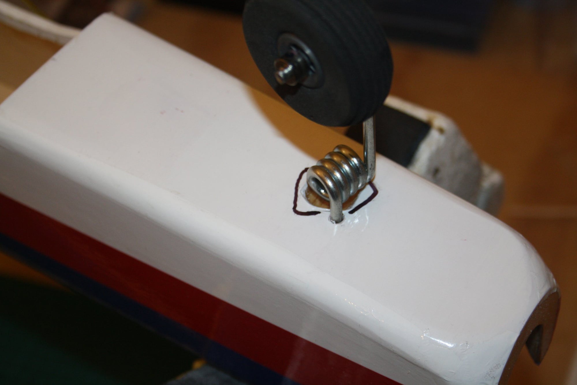
Also, note the spring of the landing gear is sunk into the balsa bottom sheeting.I did sunk my landing gear a while ago and today I realised that in order for it to allow steering I need to cut much more then my original cut.As to the horn, the photo from the front demonstrate that there is no way to have it anywhere but the top of the engine mount, which is where I am going to place it. To accommodate its larger diameter, I had to cut a relief into the firewall.
Cheers,
Eran
I do not think that the steering for the New Era III was actually possible as "designed". The plans show the horn in both the top and side view, as being under the firewall.
Also, note the spring of the landing gear is sunk into the balsa bottom sheeting.I did sunk my landing gear a while ago and today I realised that in order for it to allow steering I need to cut much more then my original cut.As to the horn, the photo from the front demonstrate that there is no way to have it anywhere but the top of the engine mount, which is where I am going to place it. To accommodate its larger diameter, I had to cut a relief into the firewall.
Cheers,
Eran
 08-30-2018, 06:23 AM
#77
Thread Starter
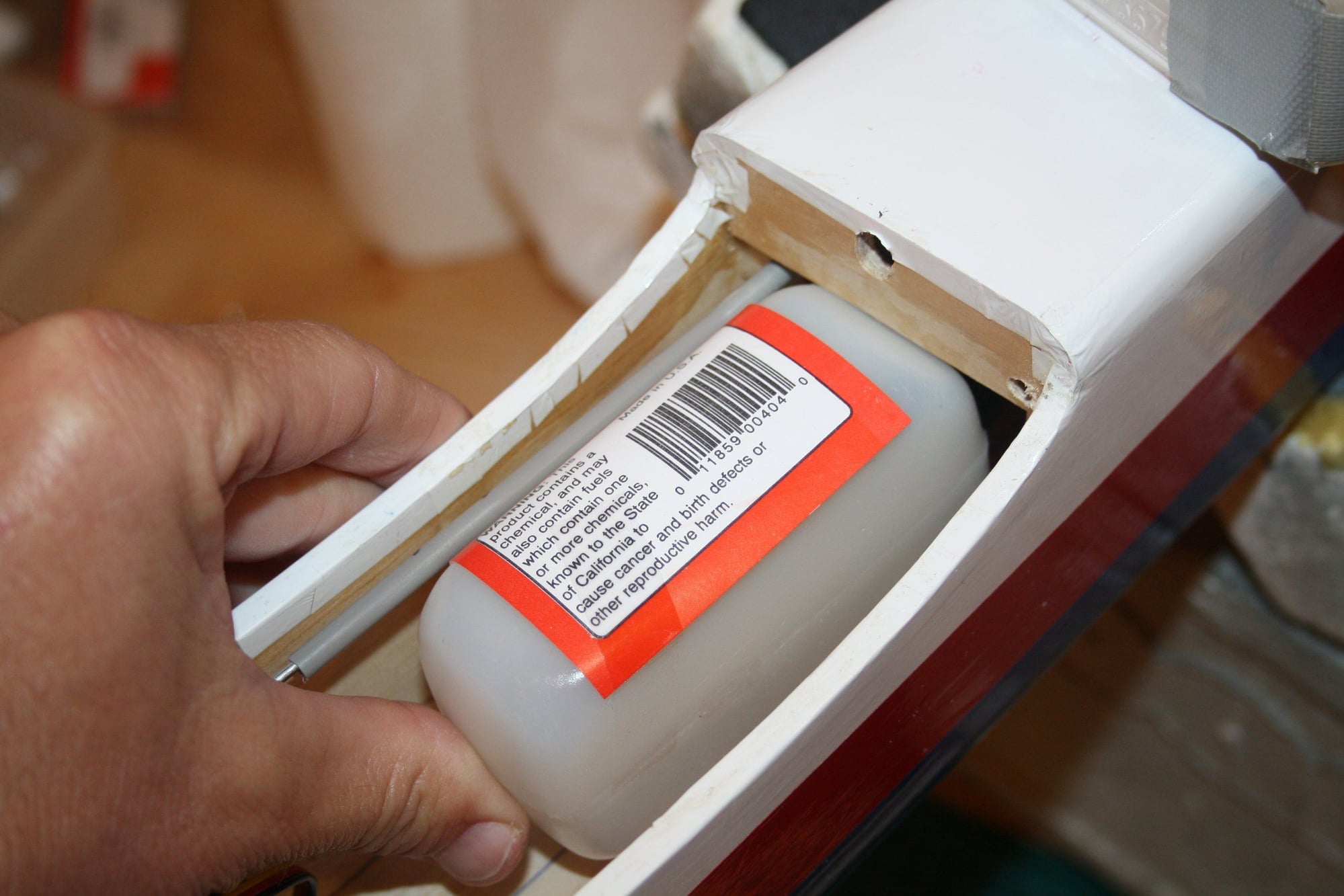
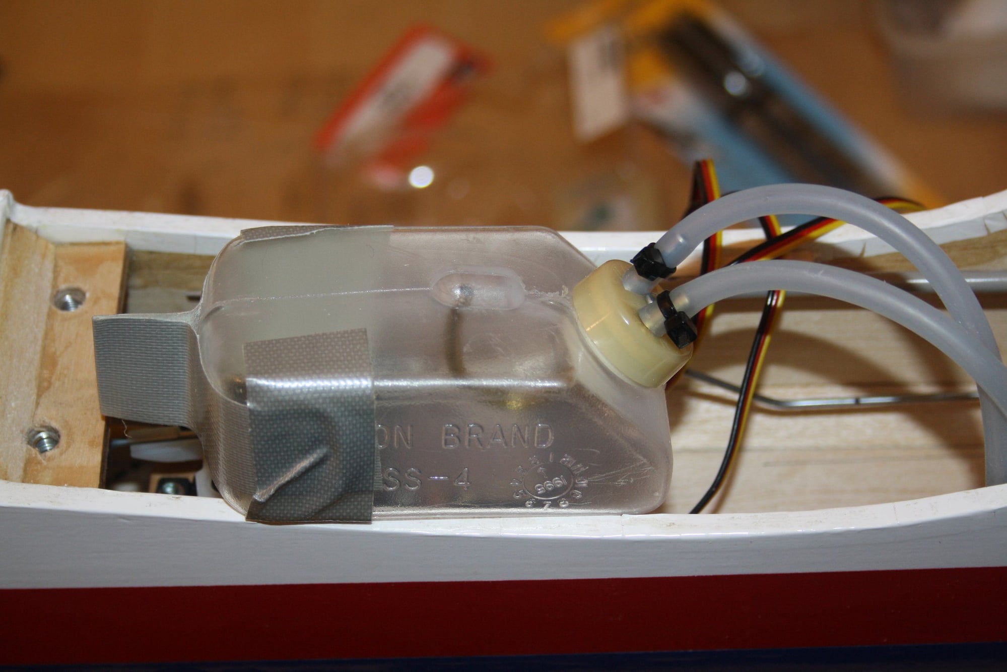
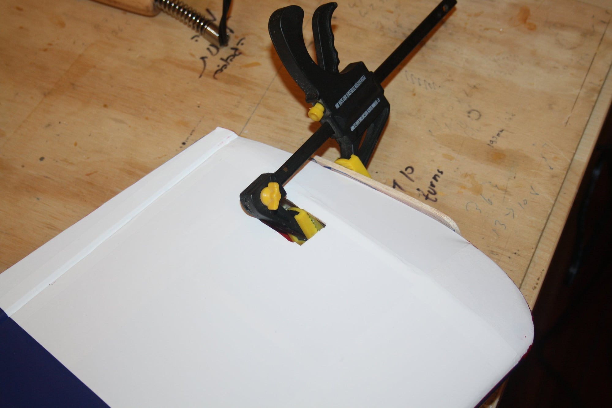
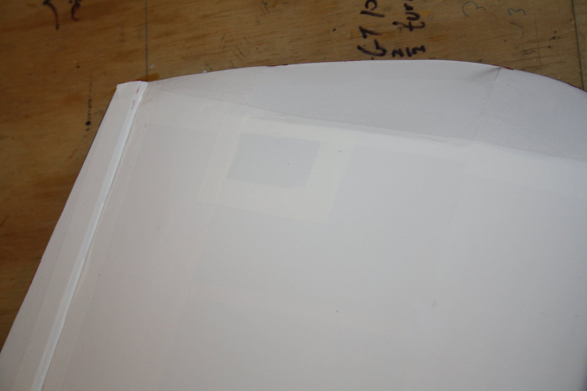
I was dealing with yet another setback today, this time with the fuel tank.
As I predicted (in my head) when purchasing this fuel tank (as per the plans), there is no way the clunk can reach the "top" when inverted. The distance from the cup and its angle (pointing the brass tubes downwards) just not going to work.Since there is no hatch, all the fuel tank handling is done from the back through the former, hence, the tape "pull back" solution.
I still cannot figure out in my head a good way to get a rod working past the fuel tank when in situ reaching satisfactory to my steering solution.
.20 size is a size too small. I just lost interest in this project. I need a break.
Cheers,
Eran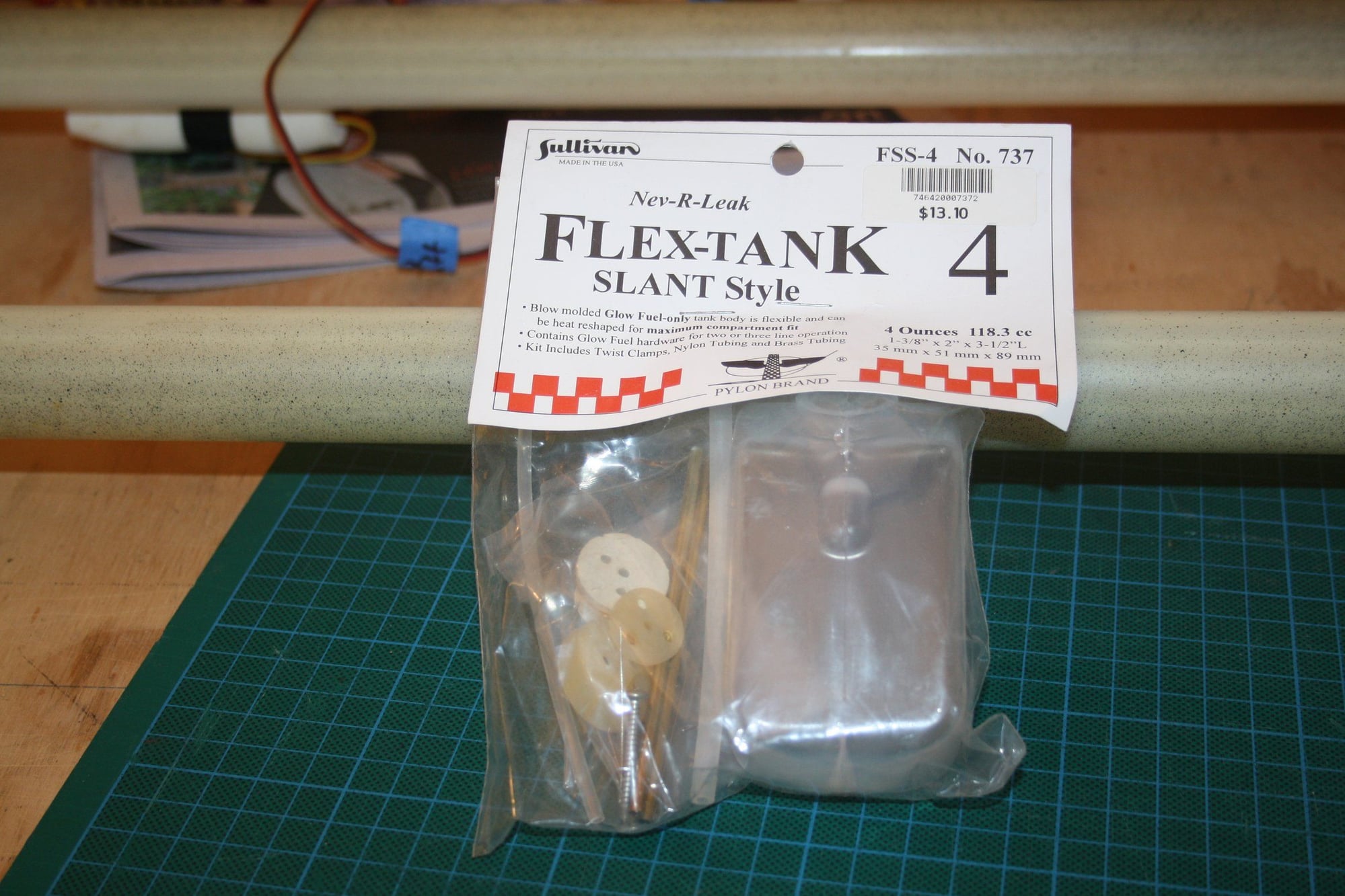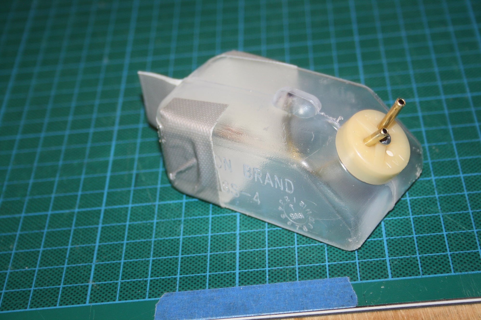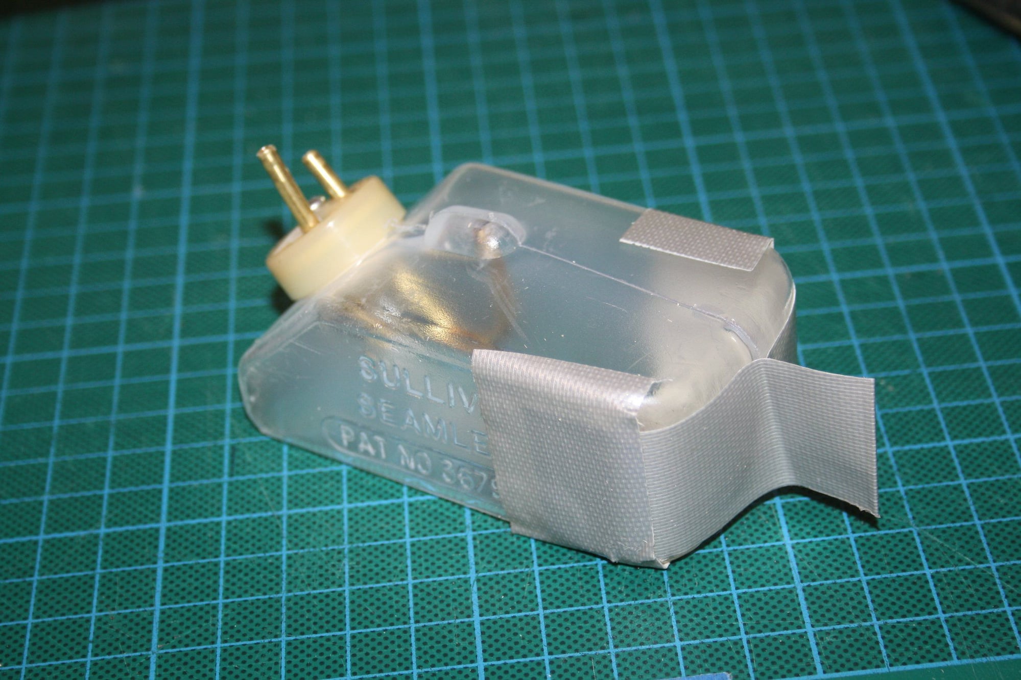
08-30-2018, 02:42 PM
#78

Eran, don�t lose interest. Just set it aside while you think out these problems. Scratch building is problem solving building. Think out a solution.
I don�t do nose gears, but most that I see the steering arm is located on the bottom. If you can bend you own gear, I would make it longer so the coil spring clears the bottom of the engine compartment. Fill in and cover the bottom. Place the steering arm on the bottom. Bend the axle part so axle is in same location as shown on plan. Hopefully you will have enough room to do this. Run your steering rod to the bottom and steering rod will then clear the fuel tank. I would run the steering rod inside some plastic tubing. Tack glue the tubing along the run. I use GOOP glue for tack glueing plastic tubing.
You can also run the steering rod along the top next to the fuel tank. Again run in plastic tubing. I�ve been using fishing tank plastic tubing. Running throttle cables.
I do coil spring tail wheels so doing a nose gear should not be too difficult.
For the tank just bend the brass tubing so it points straight to the back and be mid-way in tank height. I use tie-wraps to secure fuel tubing to brass tube. Clunk should then move freely top to bottom.
These are suggestions. Think it out and solve the problems.
08-30-2018, 03:44 PM
#79
Thread Starter
ETpilot - Thank you for the reply. It is appreciated.
The only reason I am building these old designs is to replicate them as close as possible (within reason of modern radio gear and engines) to the original.
This is my 5th scratch built / kit building in a row for the last 4 years (out of probably over 12 scratch built / kits I built so far). It is also (by some margin) the smallest one, which is the frustrating factor. There is no space for anything. I predominantly build 20cc-50cc size aeroplanes recently.
The error on this build is my own. I didn't see the pin-hole size hole in the firewall drawing for the steering rod, neither I "scooped" the firewall in the required location (under the engine mount) while it was on the bench. Doing it now will be very difficult. I will see if I can get there somehow to get it done. If not, I may cut out the entire front to allow access, I will think of it again at later stage.
As to the fuel tank - as an Engineer, I am lost for words. However, if it was designed ONLY for pylon racing, then there is no need to fly inverted... However, this is the fuel tank specified on the plans.
Cheers,
Eran
08-31-2018, 03:43 AM
#80
Building to replicate does add a new dimension to the problem. Hopefully you can find a solution with what you have so far. If not, cutting the front for access may be the way to go. Good luck with the fix.
09-02-2018, 08:39 PM
#81
Thread Starter
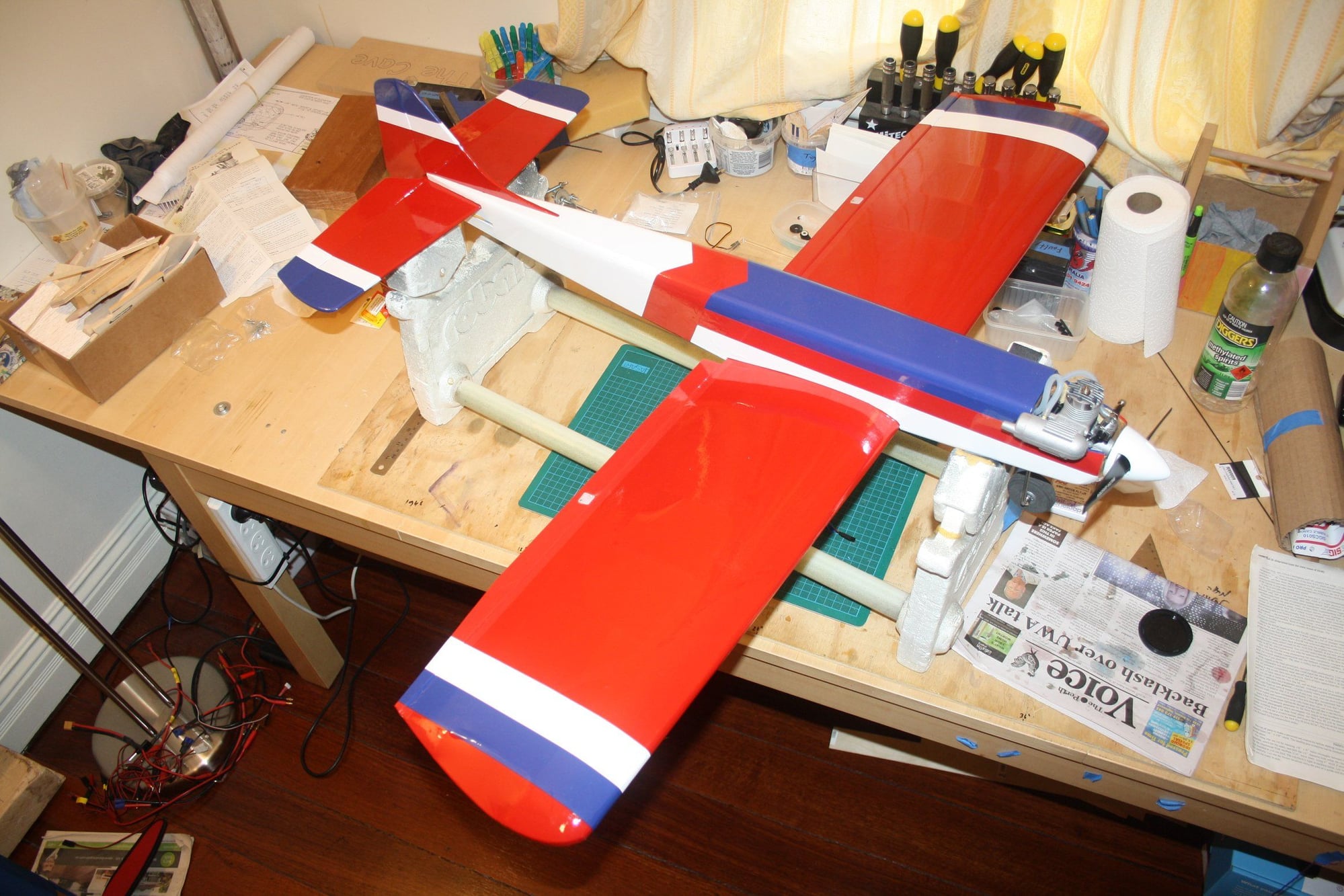
To be able to get something done, I deported the fuselage out of the Cave so I won't need to look at it.
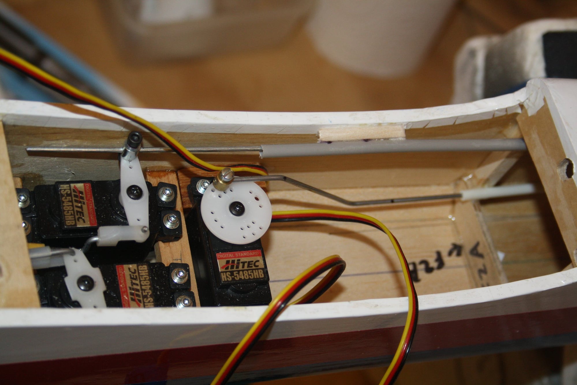
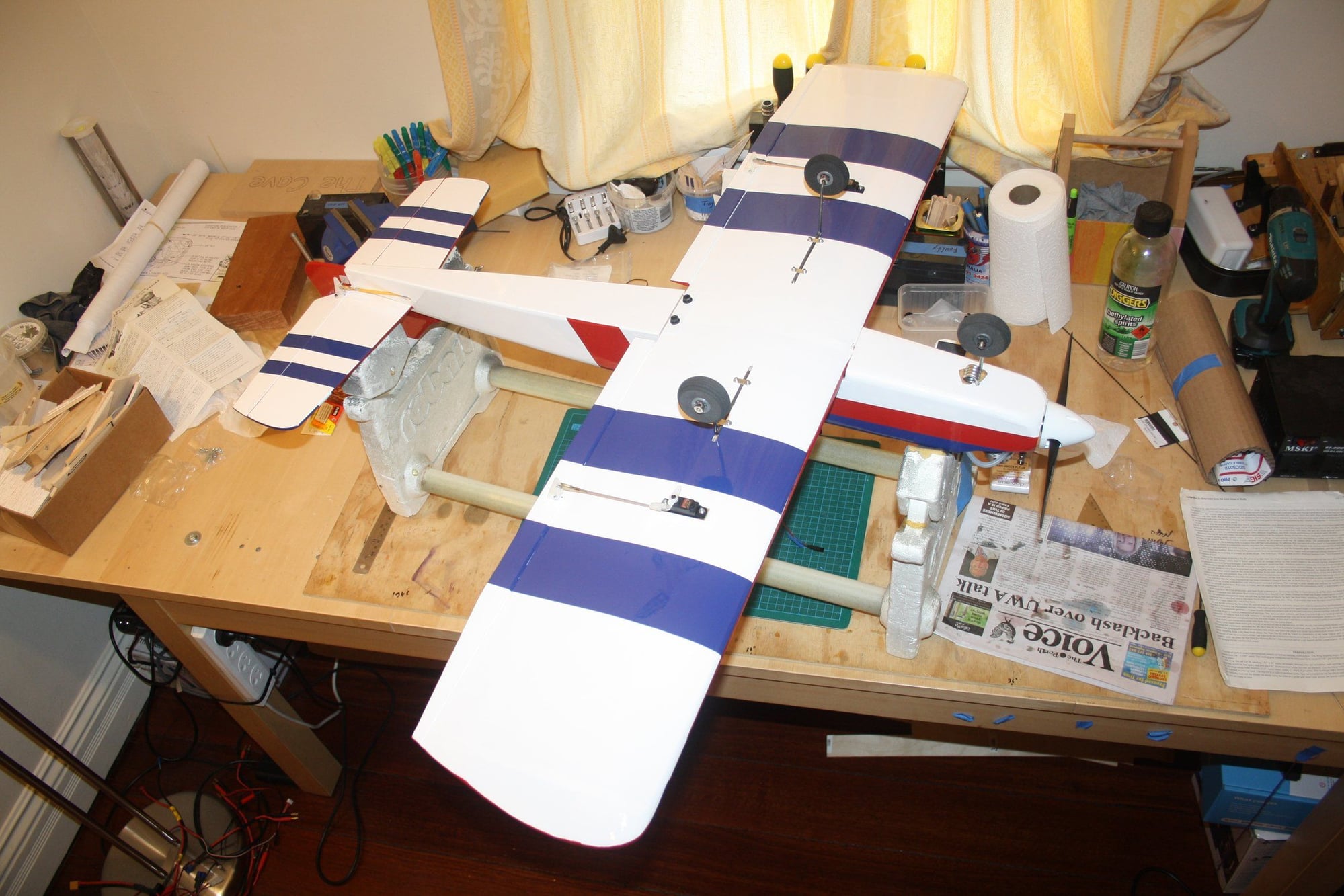
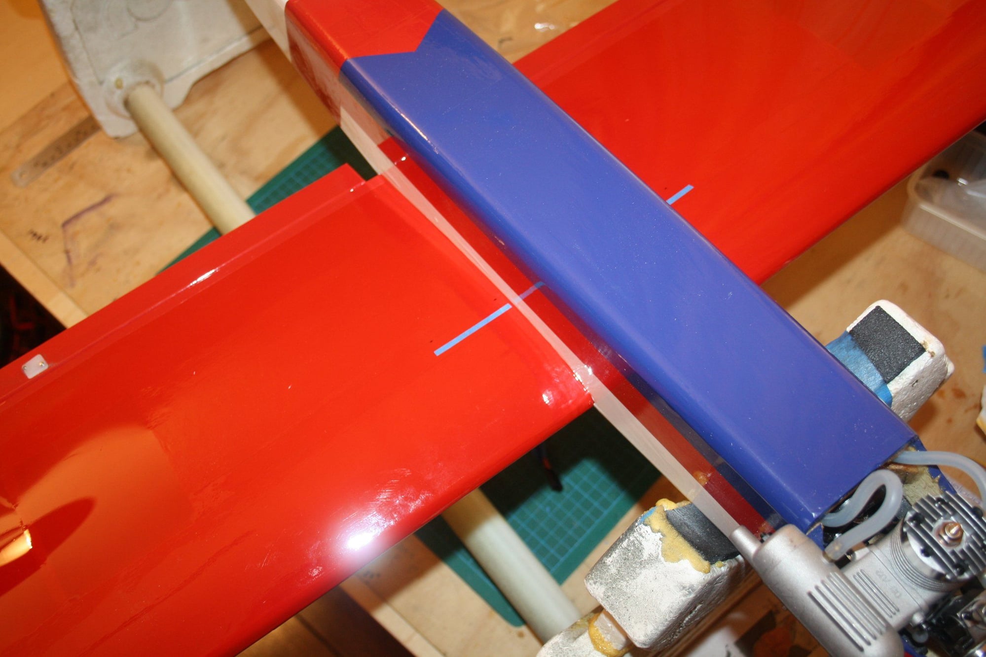
I decided to go ahead and complete some work on the wing, so I set up the ailerons servos and finlised to covering scheme on the top.
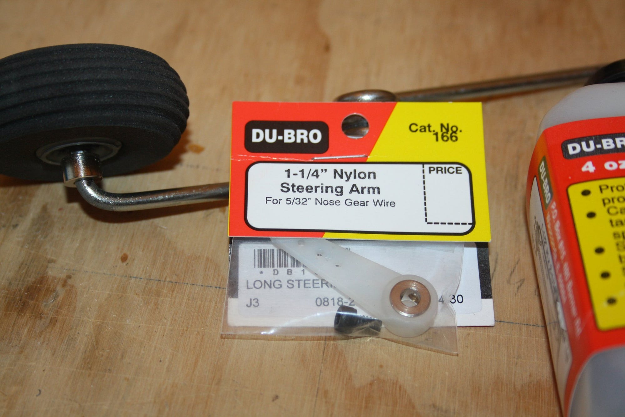
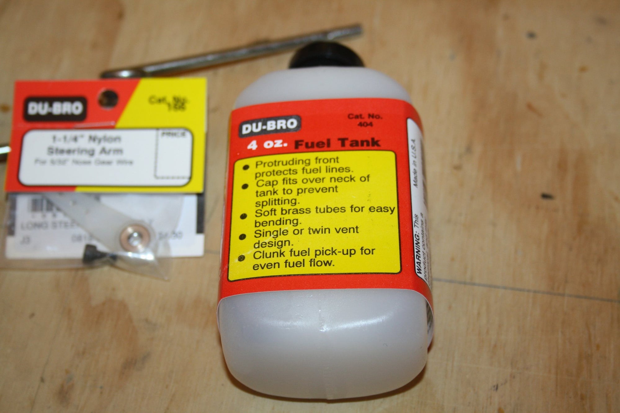
I did some RC shopping, got a new fuel tank and steering arm. I may give it another go sometime this week.
Cheers,
Eran
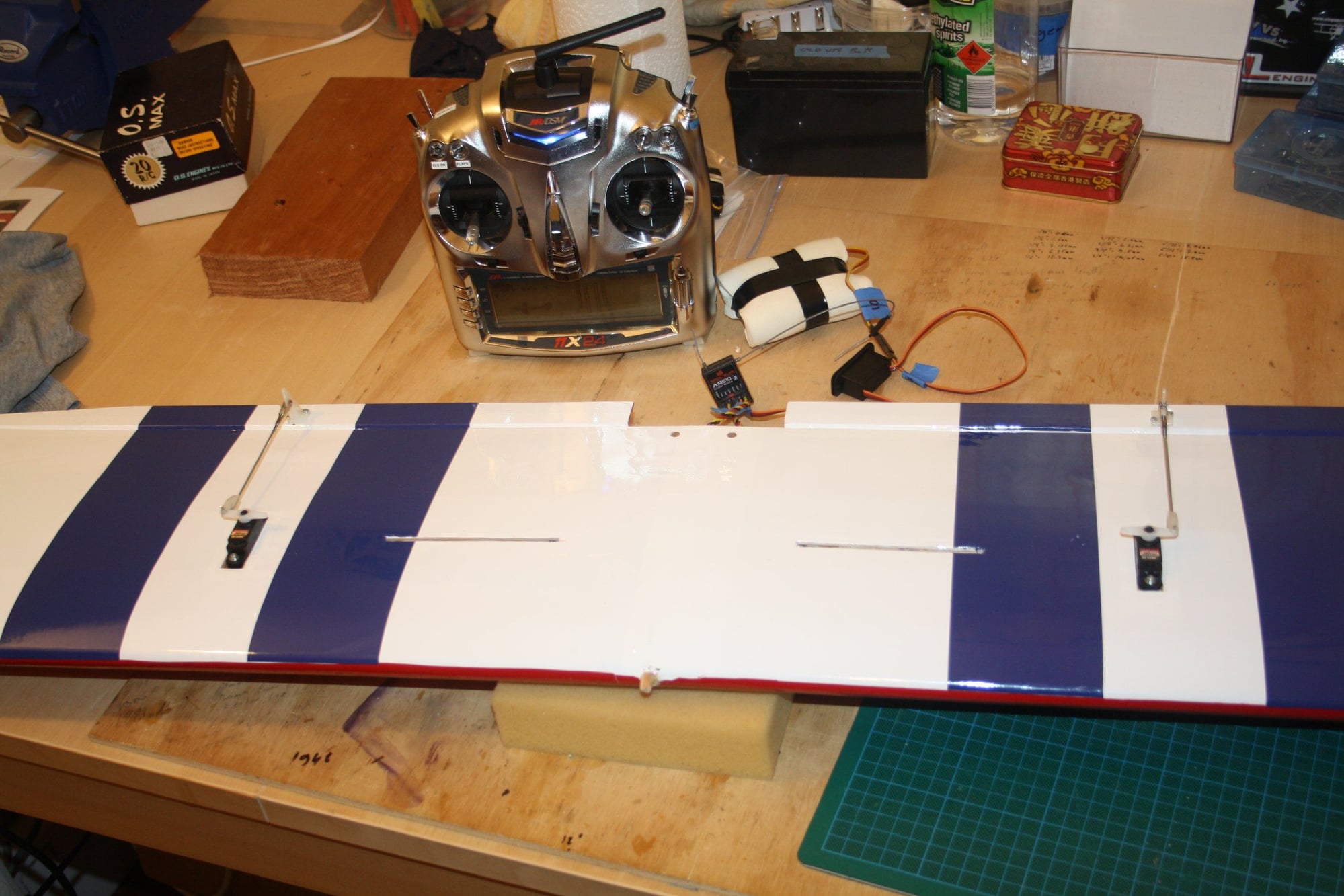
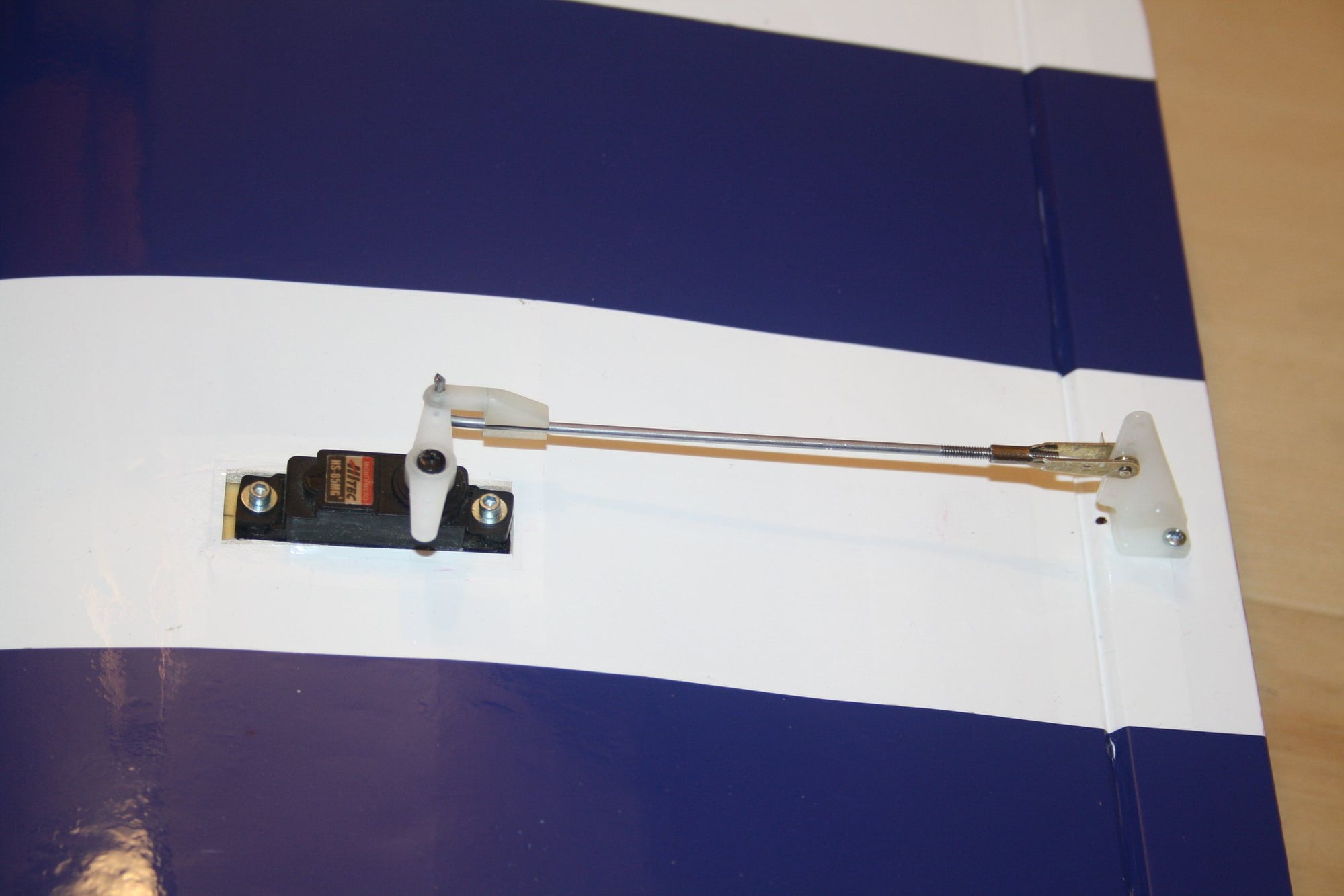
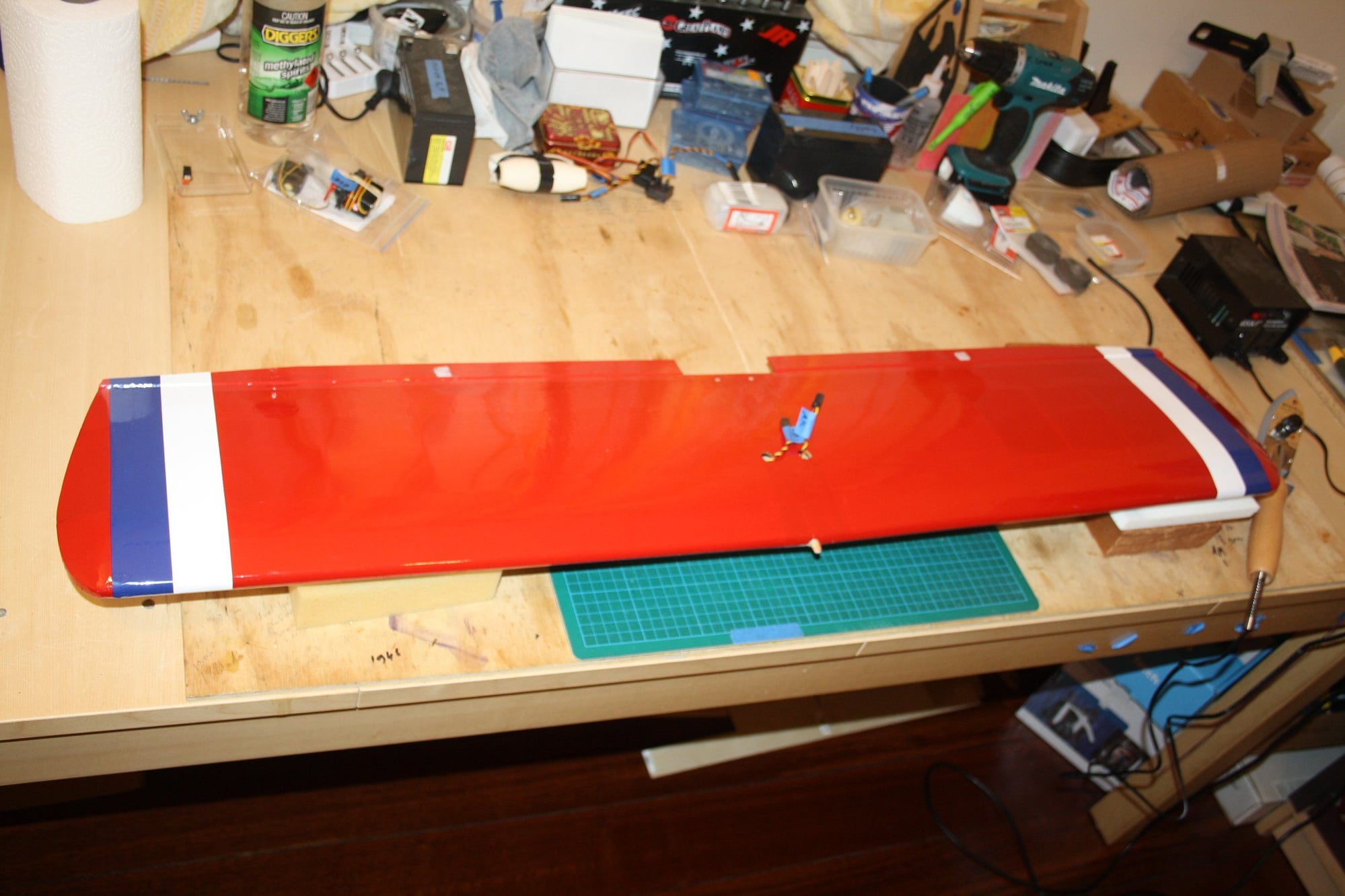
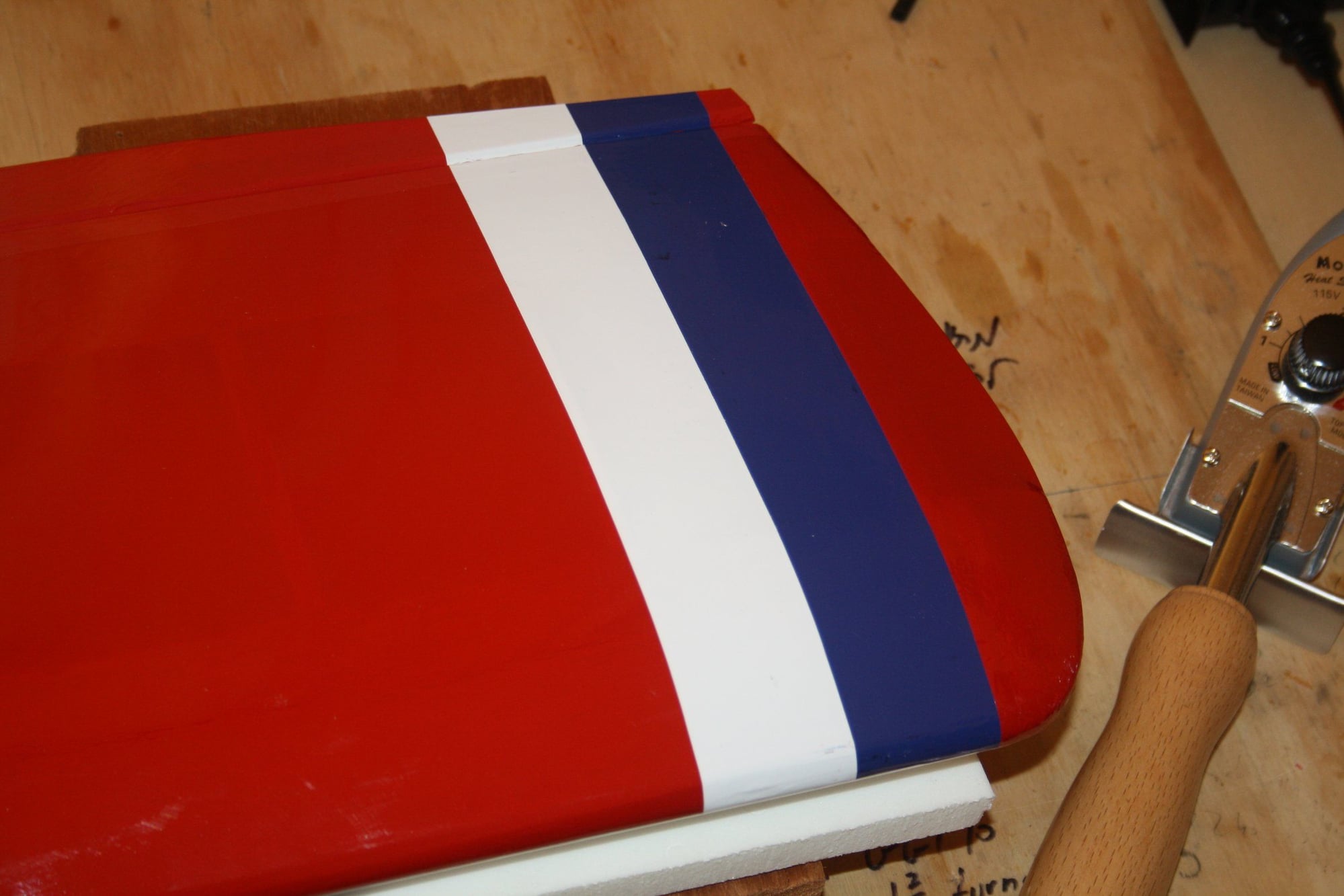
I decided to go ahead and complete some work on the wing, so I set up the ailerons servos and finlised to covering scheme on the top.
I did some RC shopping, got a new fuel tank and steering arm. I may give it another go sometime this week.
Cheers,
Eran
09-03-2018, 02:38 PM
#82
Eran, I'm glad you decided to keep at it. I may misunderstand, but it seems to me all you need is a Robart Carbide ball cutter on a rotary tool. I've used mine so many times I don't know what I did without it. It seems to me you could just cut right into the bottom with it and make plenty of space for the coil to be recessed. https://robart.com/collections/hobby...-8-ball-coarse
Jim
Jim
09-03-2018, 03:43 PM
#83
Thread Starter
buzzard bait - Thank you for the reply. I do have similar tool and this was my first plan of attack for the relief in the firewall when I get to it. It may just work.
It is the drilling of the hole for the push-rod that is impossible to do without damage to the front.
Kind Regards,
Eran
It is the drilling of the hole for the push-rod that is impossible to do without damage to the front.
Kind Regards,
Eran
09-03-2018, 10:18 PM
#85
Thread Starter
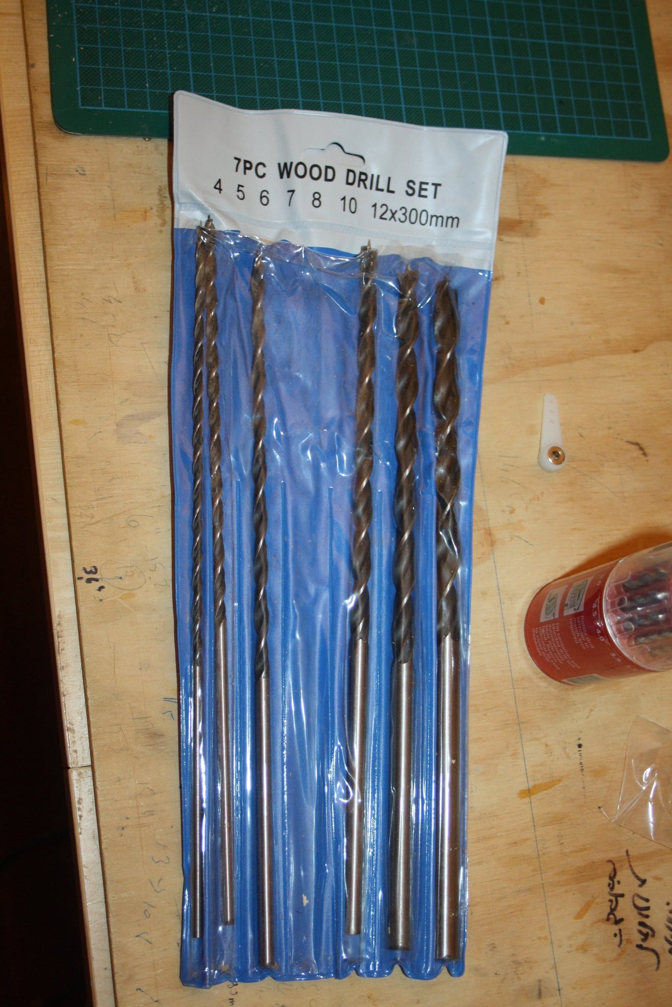
buzzard bait - No worries. I do have the very long drill bits.
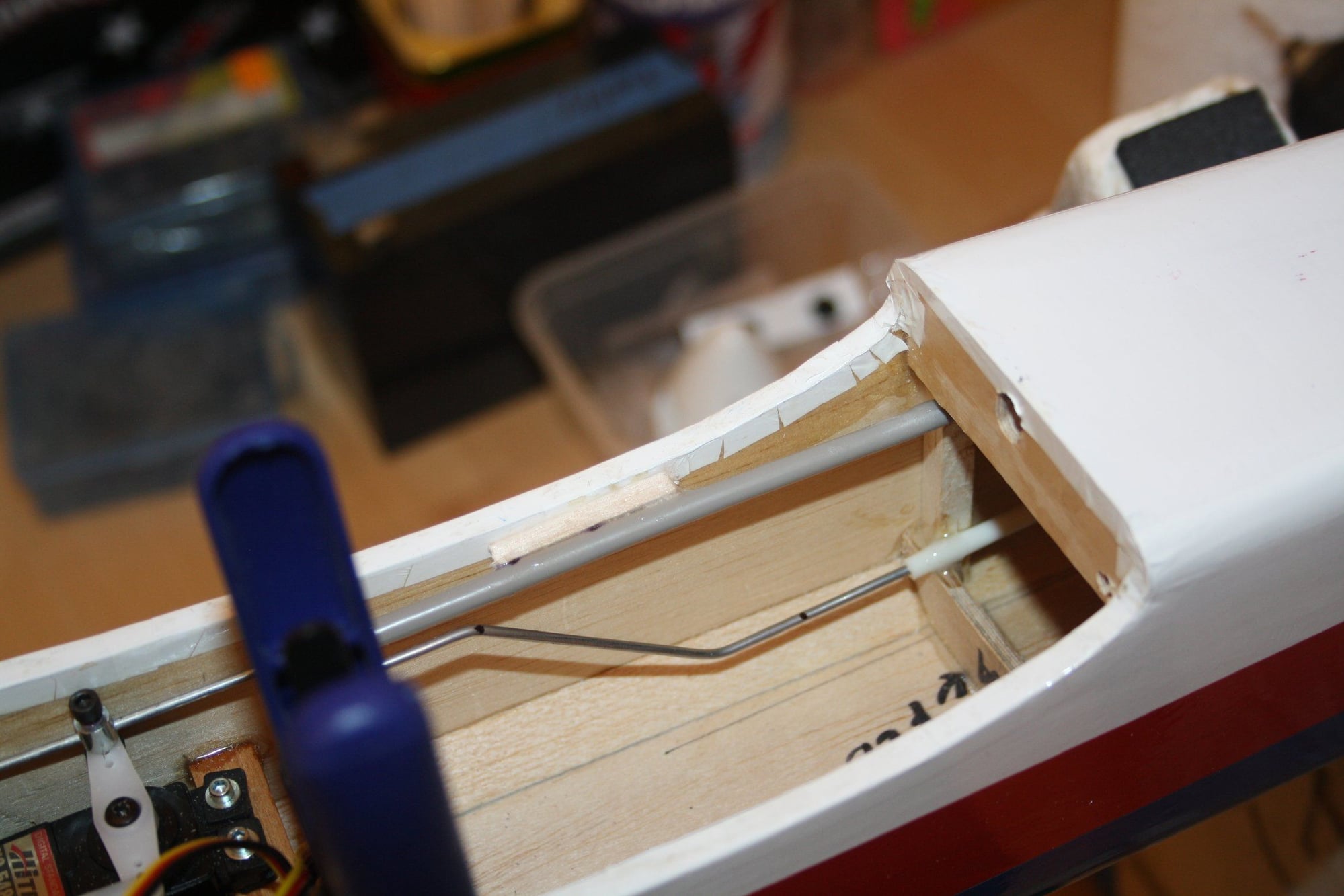
It is the fact that in order to have a horizontal line to the location requires going through the "cheeks" curved section where they meet the plywood at the back of the spinner. I will show it in a photo when I will do it.
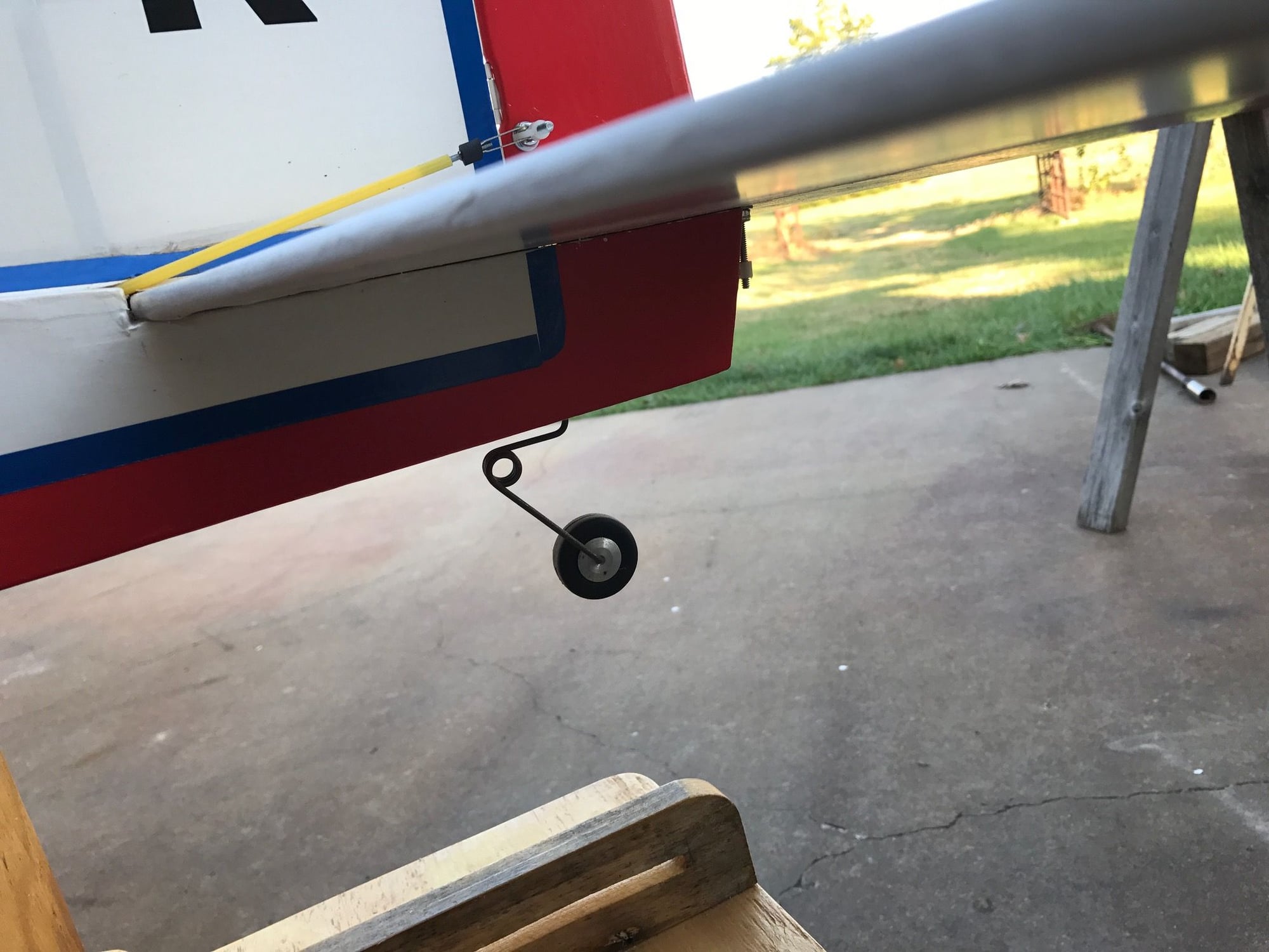
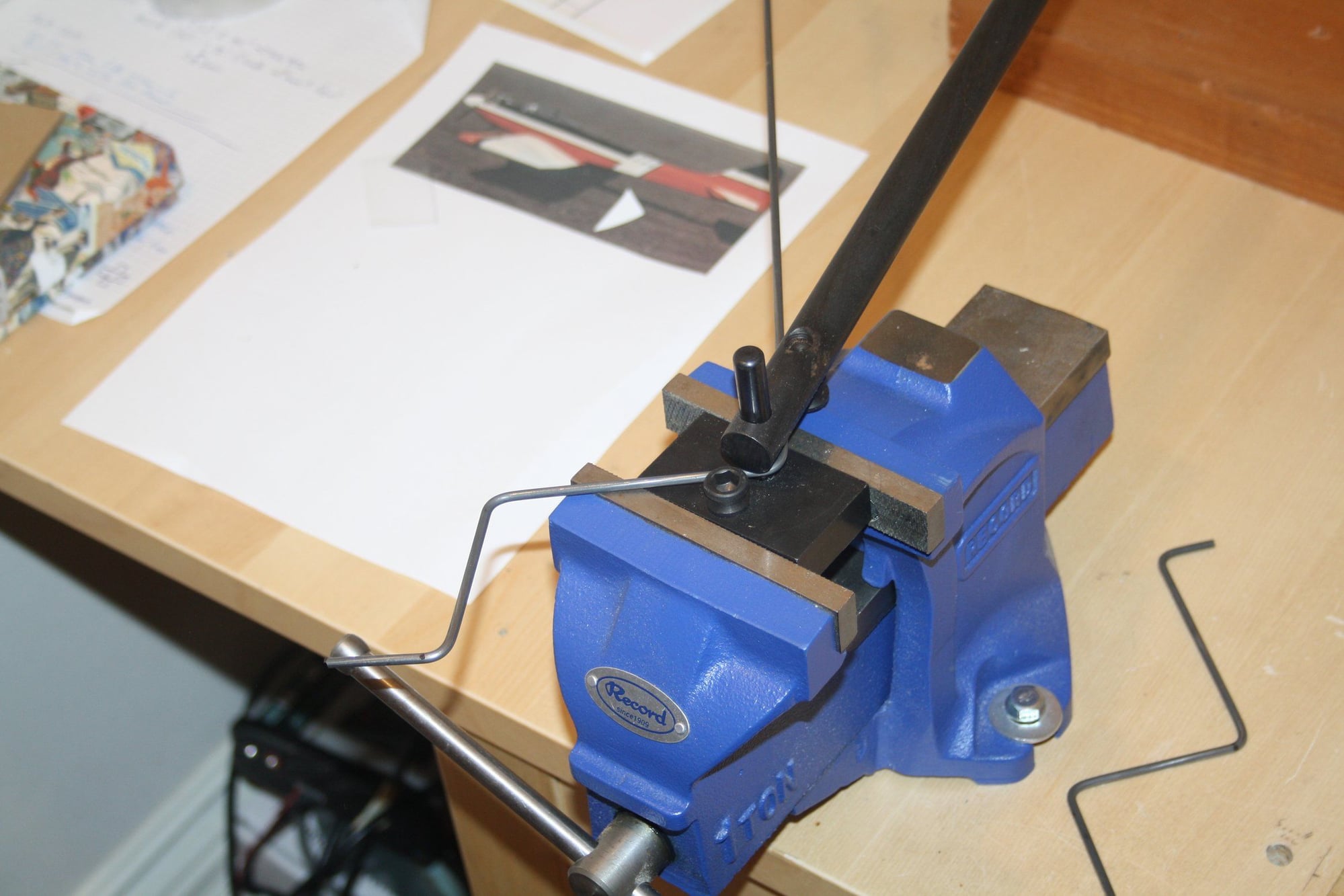
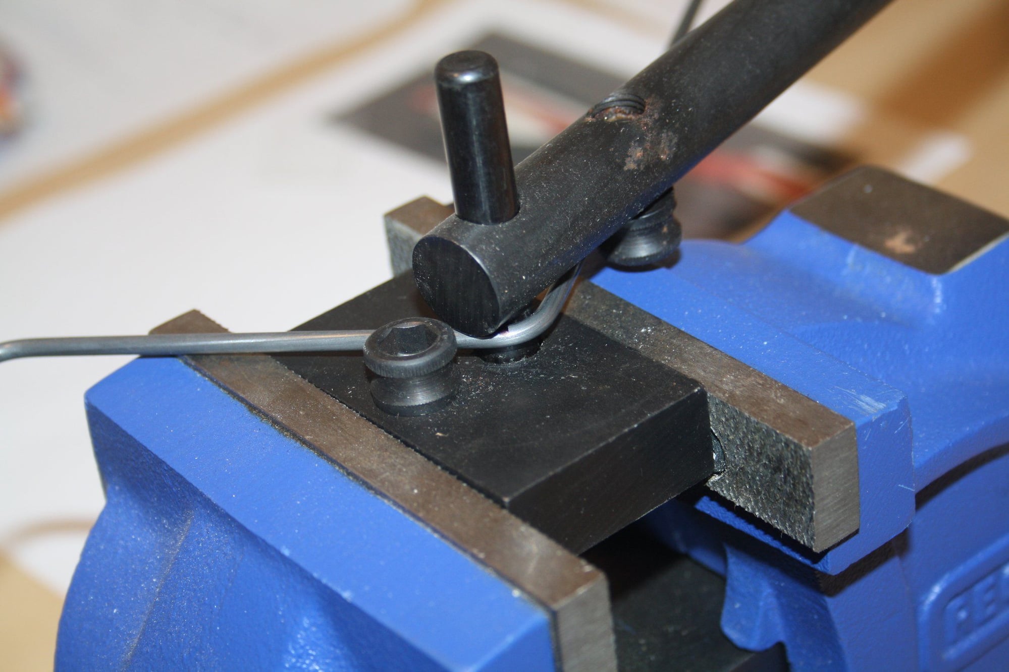
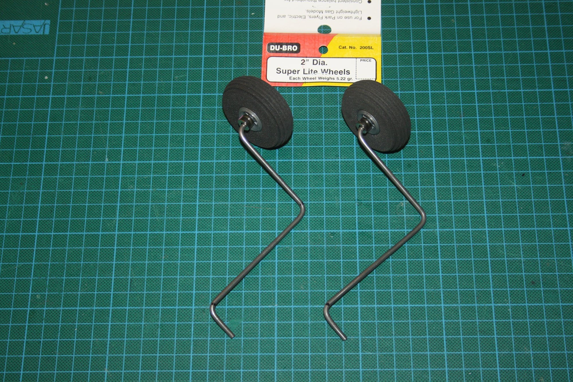
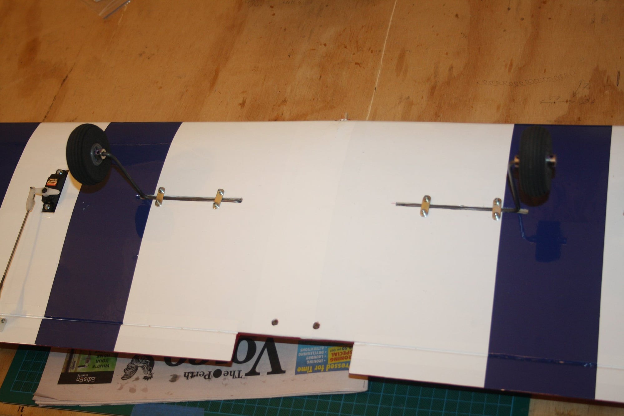
Today I completed the wing with the installation of the landing gear.
Cheers,
Eran
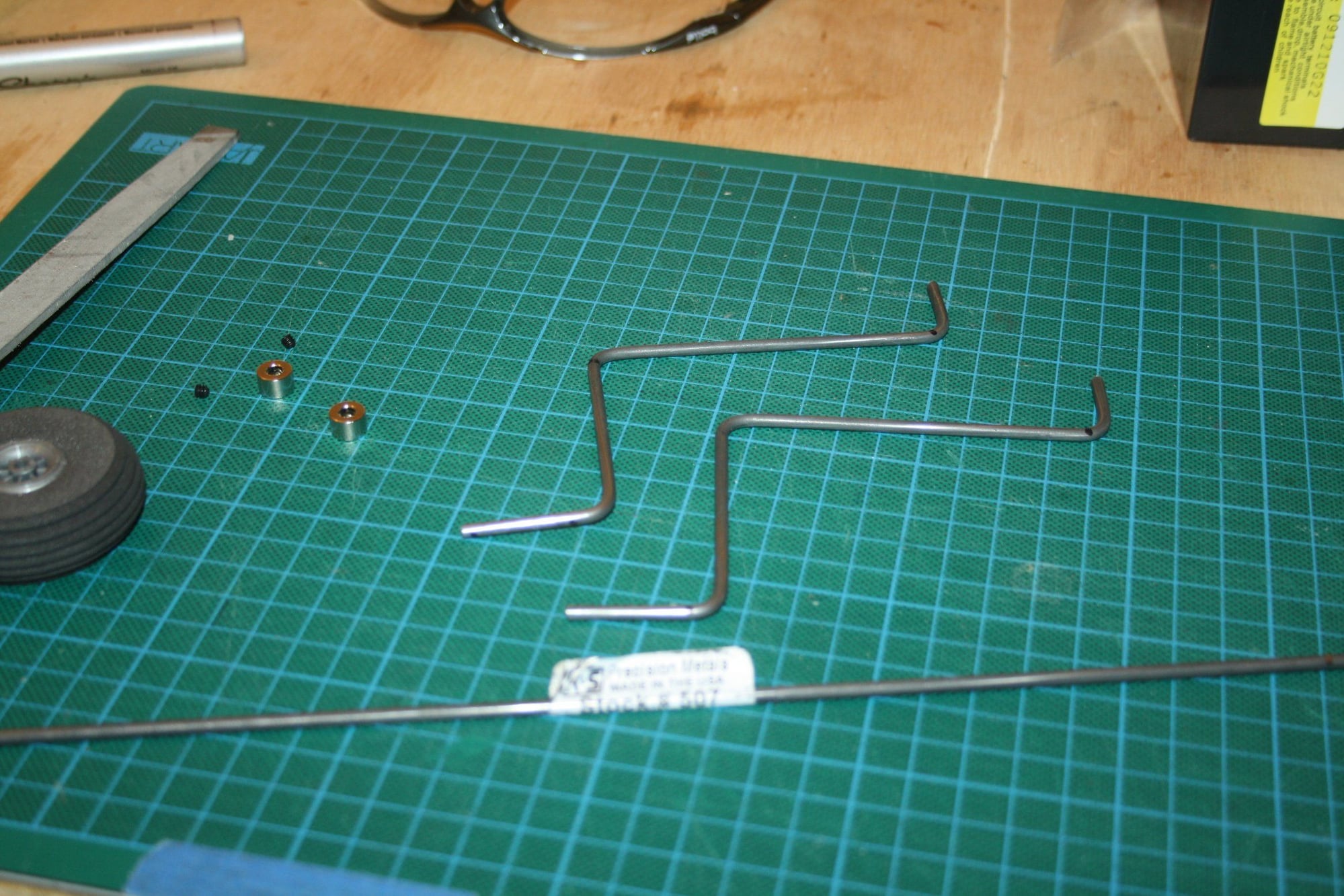
It is the fact that in order to have a horizontal line to the location requires going through the "cheeks" curved section where they meet the plywood at the back of the spinner. I will show it in a photo when I will do it.
Today I completed the wing with the installation of the landing gear.
Cheers,
Eran
09-04-2018, 06:06 AM
#86
Great, I love my K&S heavy wire bender, but it took me some practice to get predictable locations on the bends. Looks like you nailed it.
That's going to be a terrific airplane, they have been getting rave reviews for decades.
JIm
That's going to be a terrific airplane, they have been getting rave reviews for decades.
JIm
09-06-2018, 03:27 AM
#87
Thread Starter
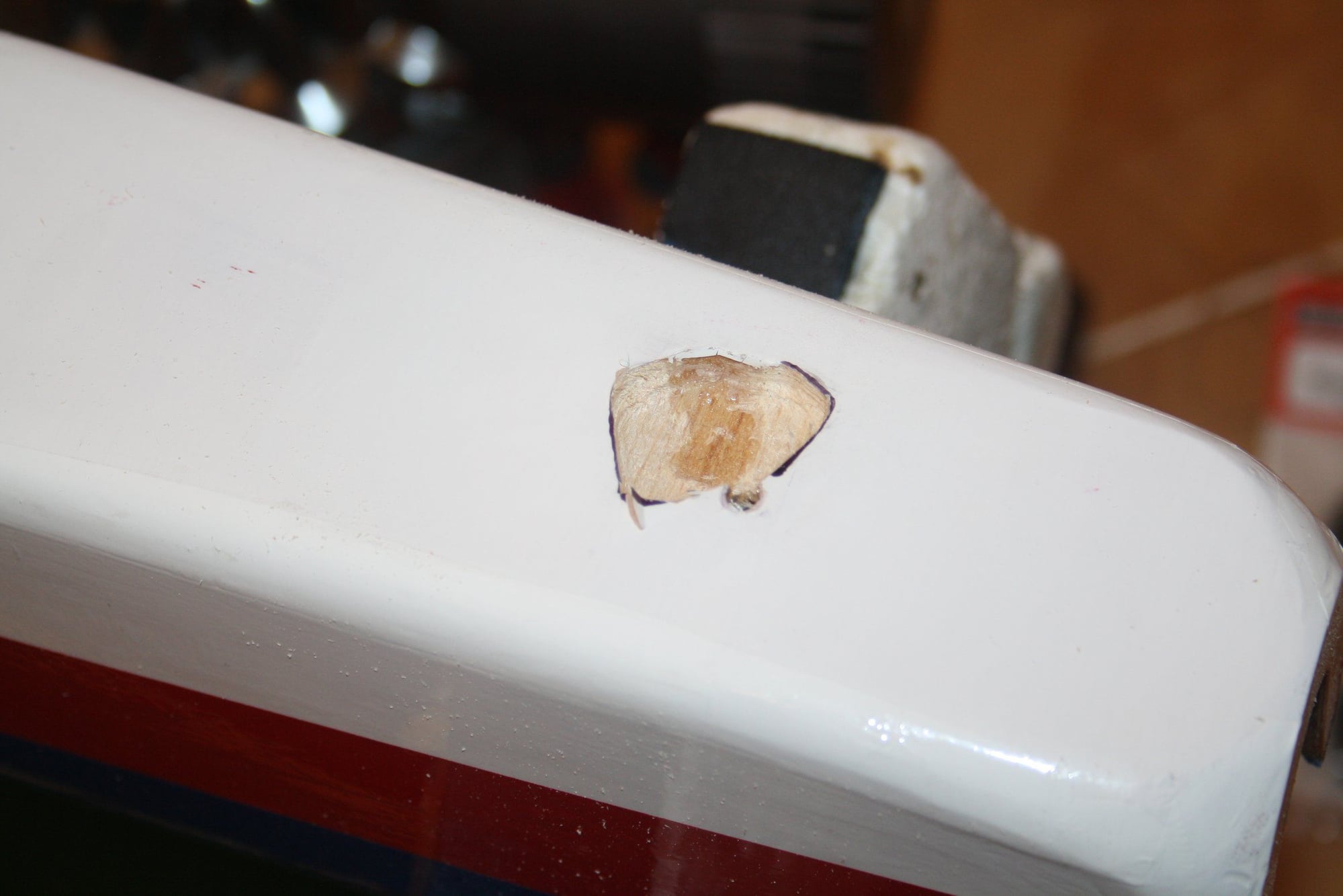
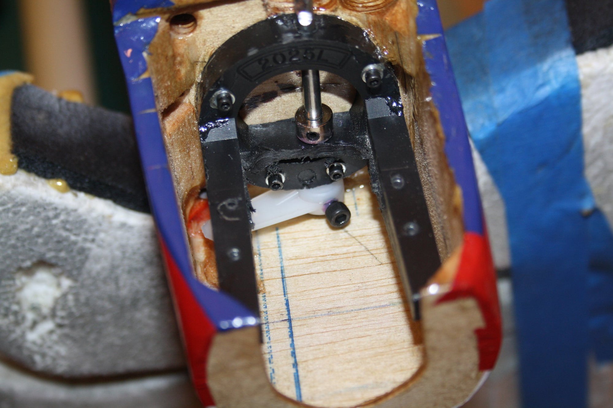
OK, it was time to face the fuselage again. Many hours were spent on resolving the steering, starting with removing the engine mount. Due to the amount of photos I will post few threads.
I marked the expected location of the rod exit from the firewall, made a calculated guess of the required alignment and drilled through the "chick" using 300mm drill.
Cheers,
Eran
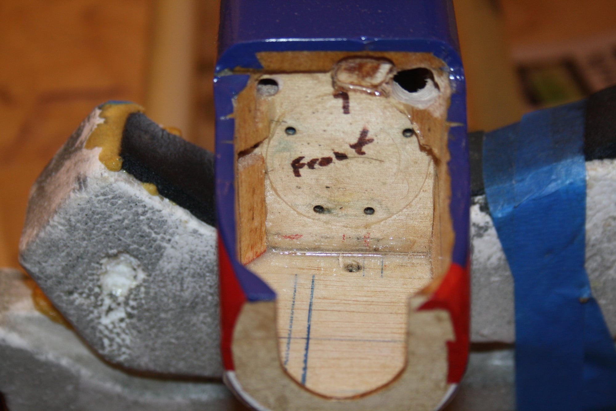


I marked the expected location of the rod exit from the firewall, made a calculated guess of the required alignment and drilled through the "chick" using 300mm drill.
Cheers,
Eran
09-06-2018, 03:31 AM
#88
Thread Starter
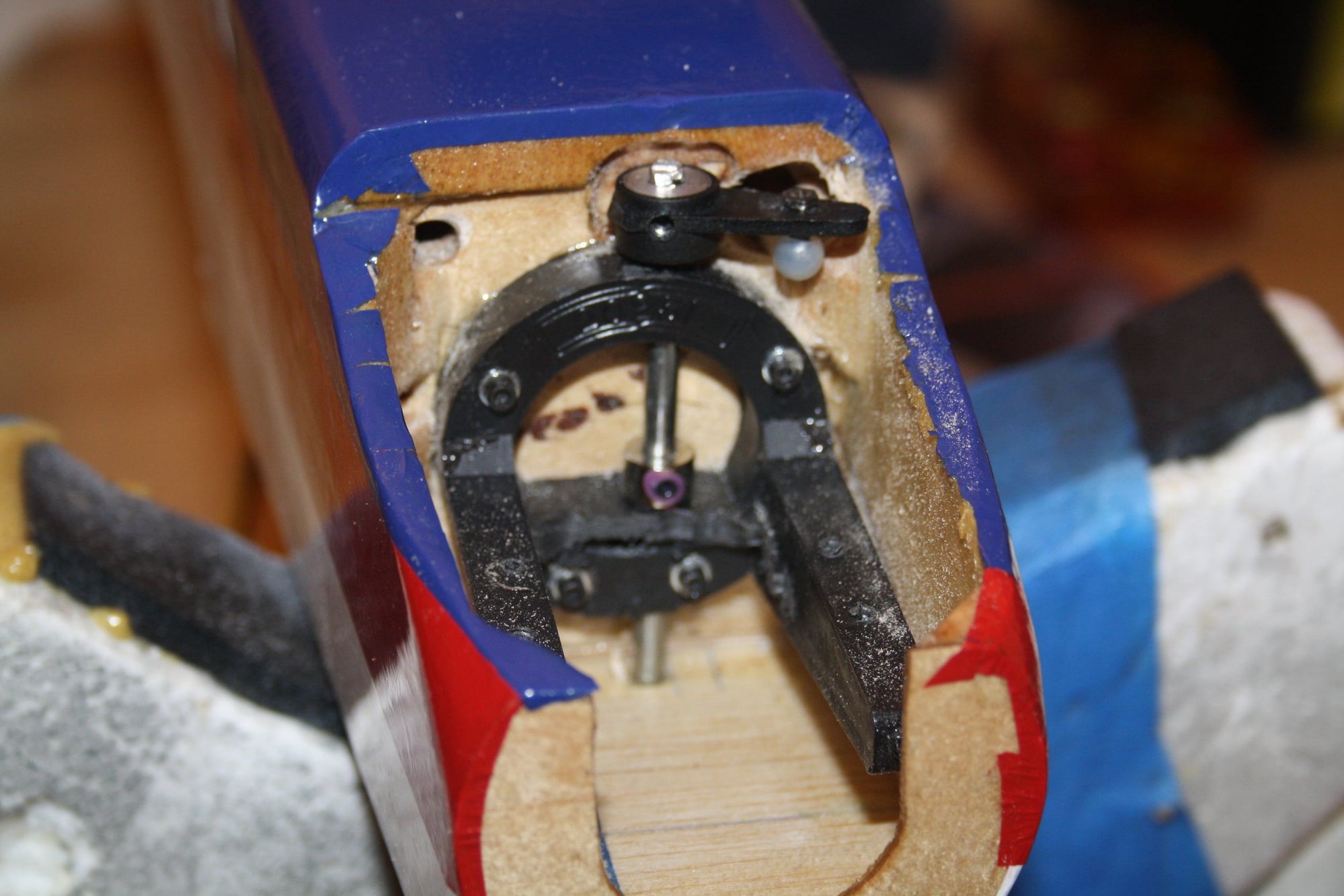
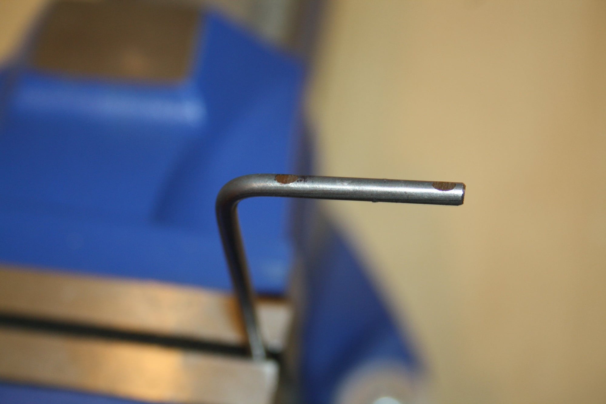
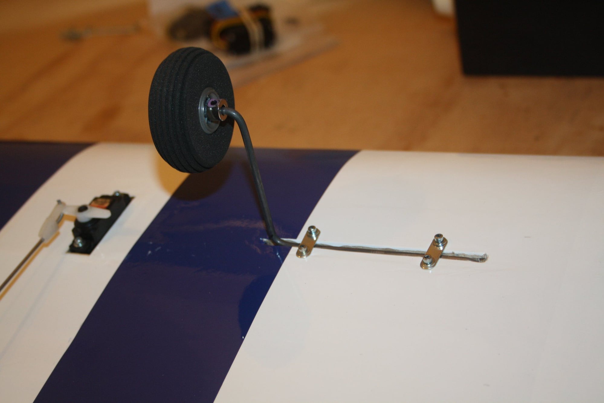
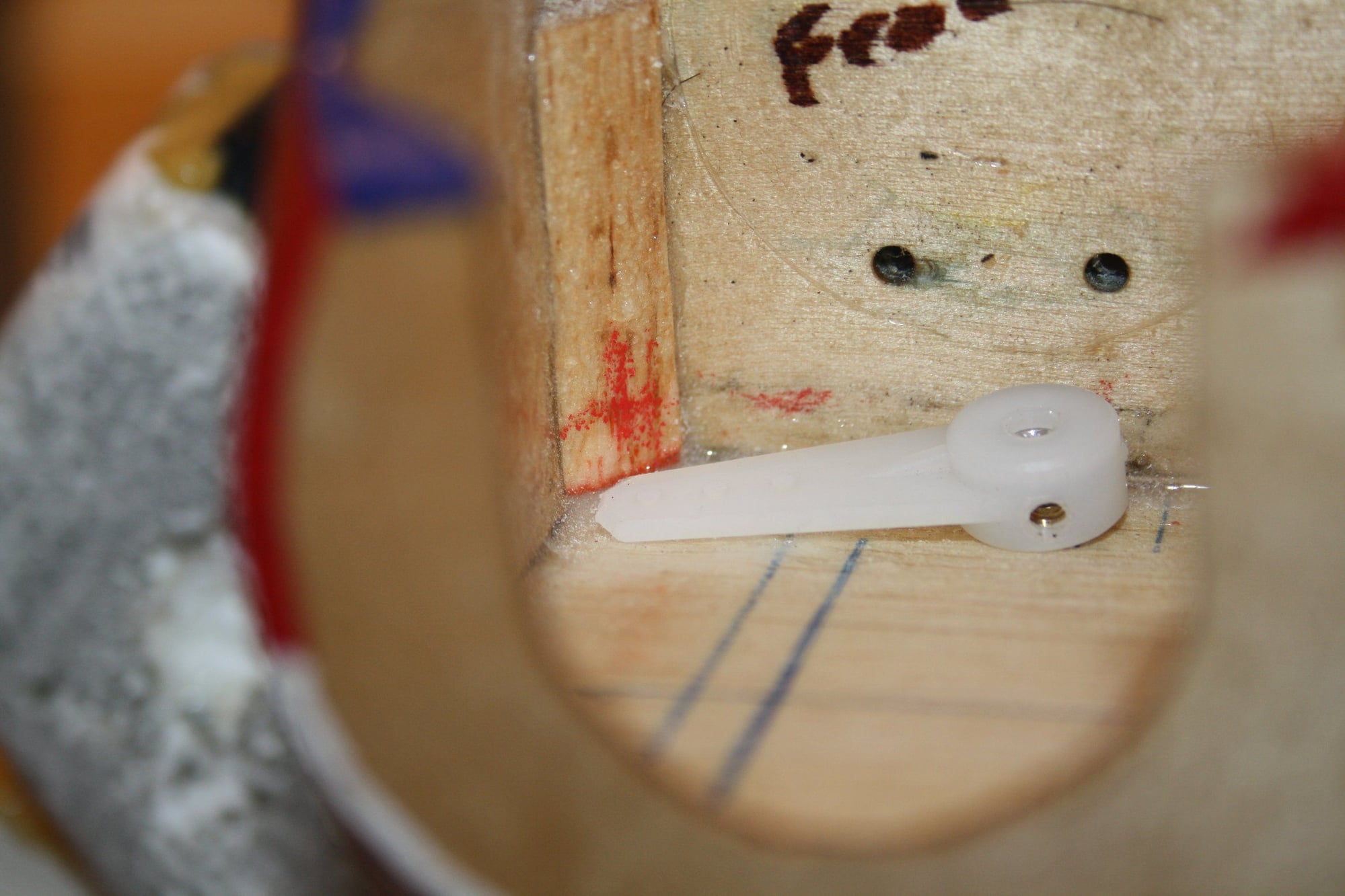
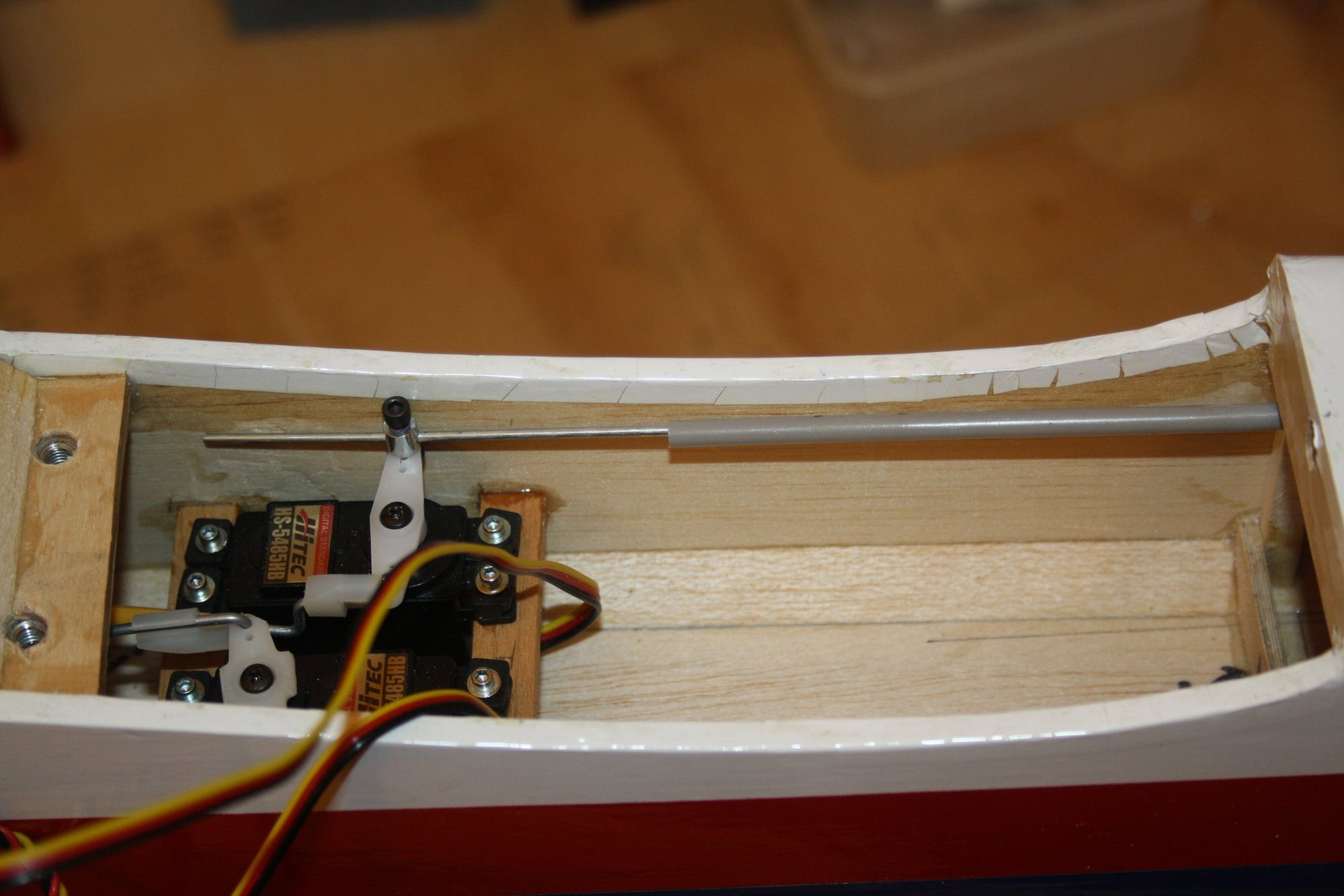
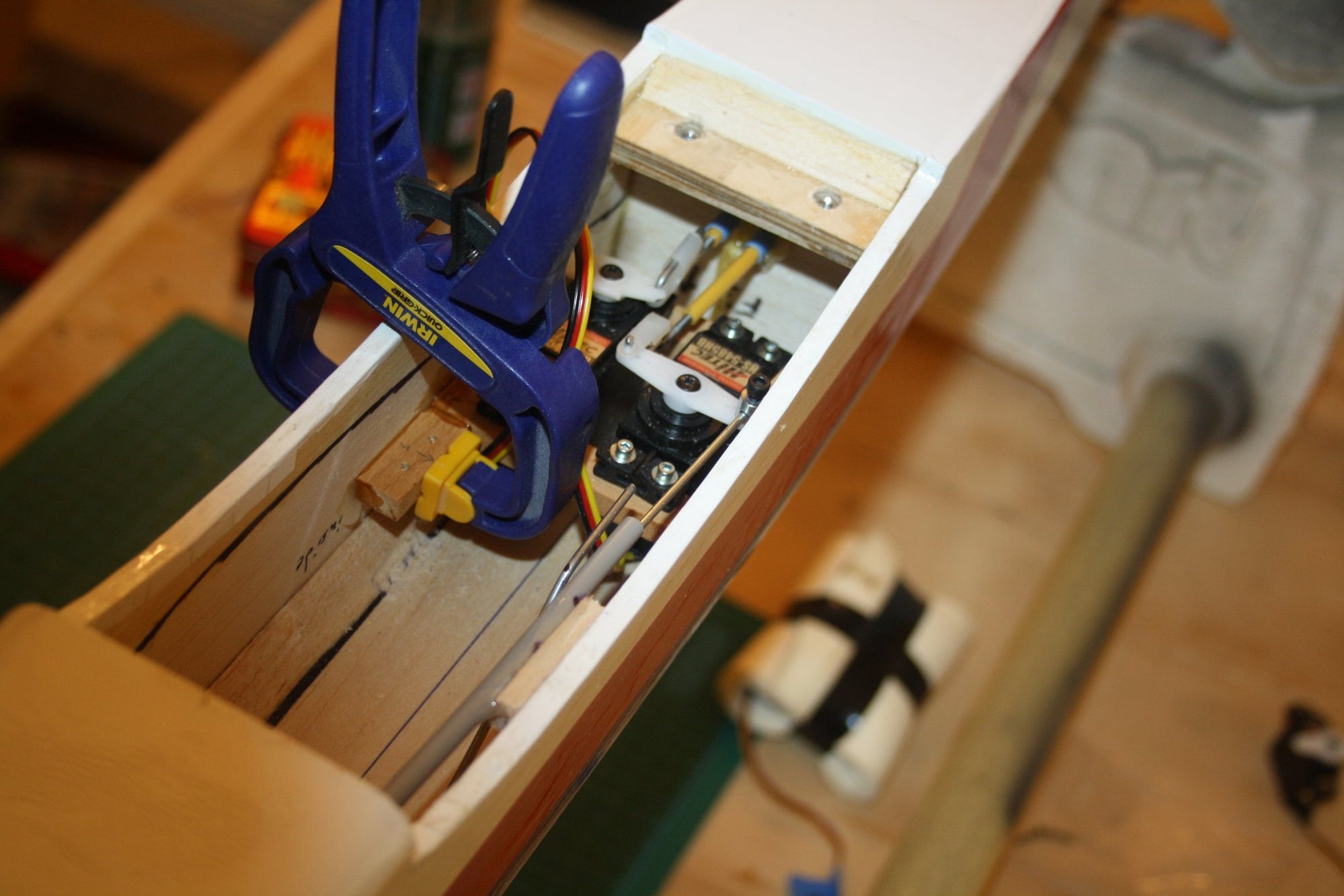
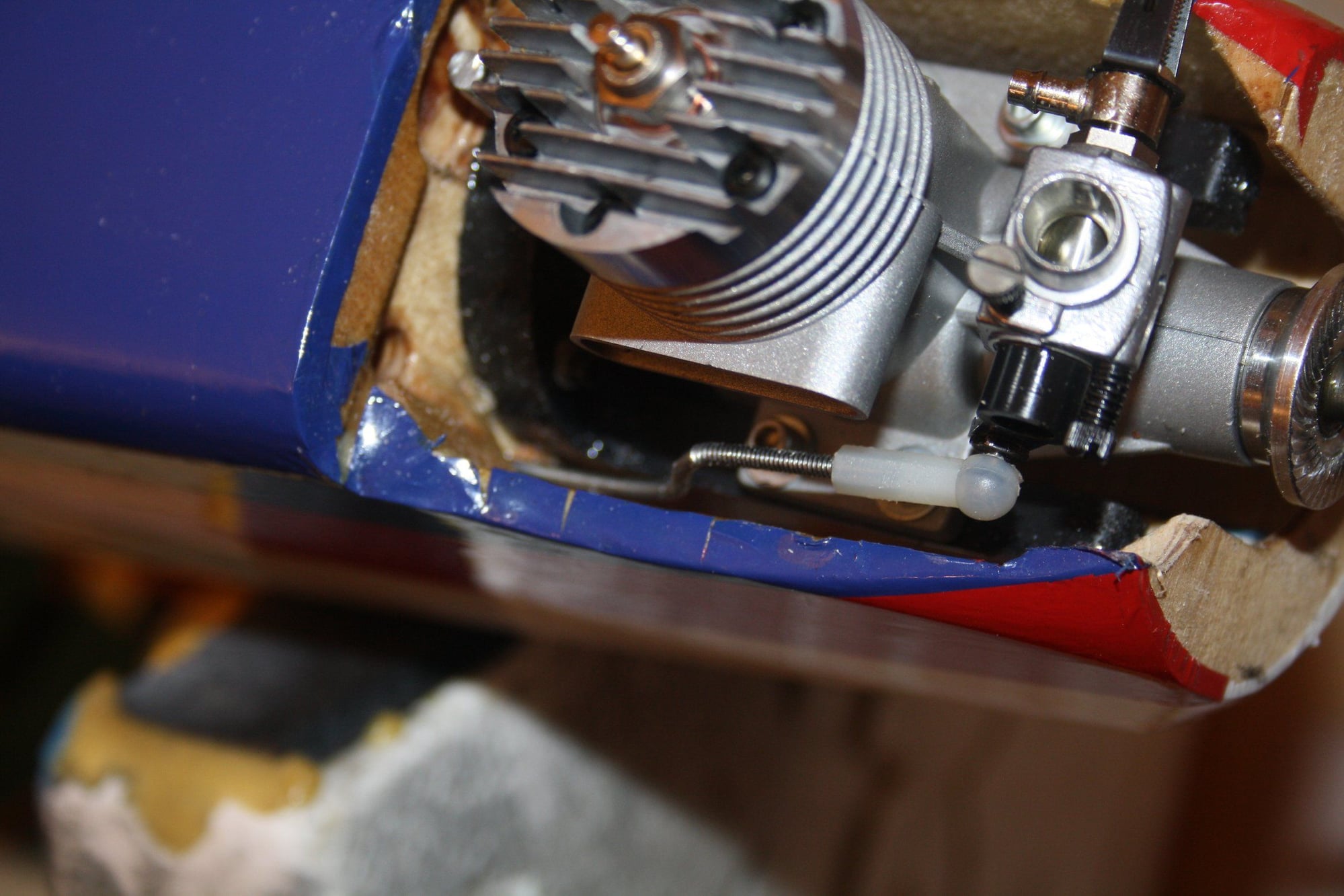
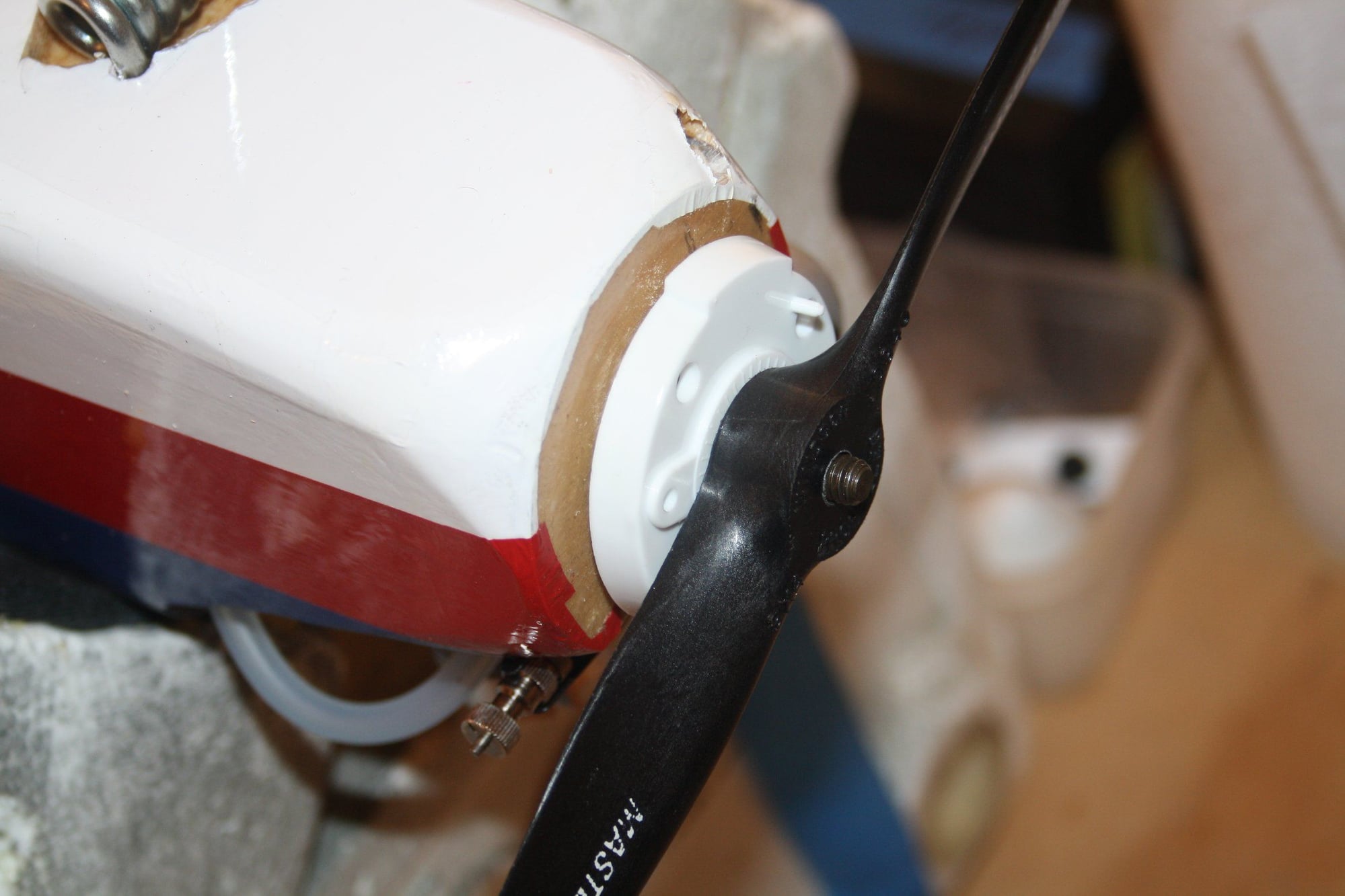
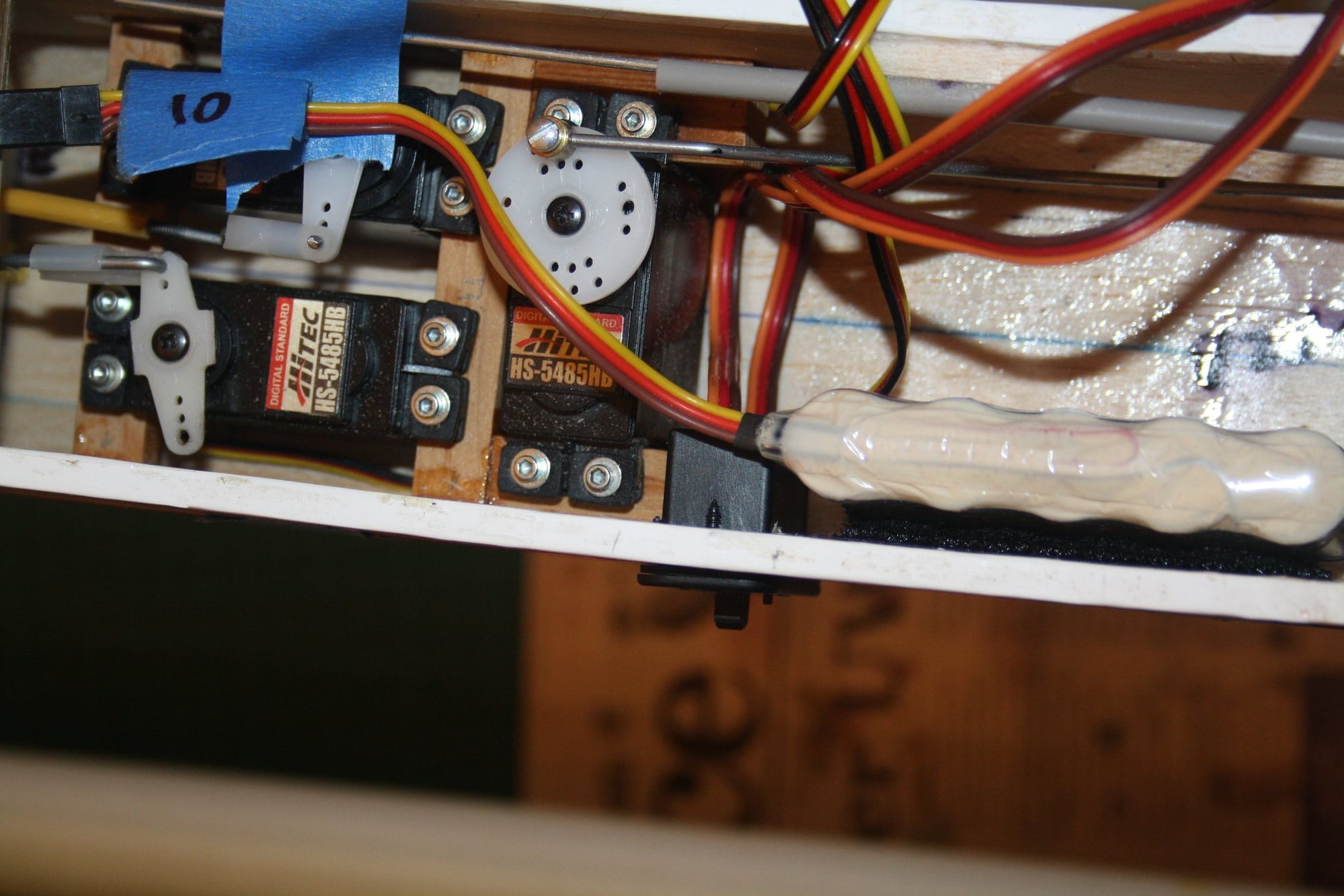
The steering arm is placed in an angle to the wheel, and an appropriate "flat" created for the grab screw.
Finally, all was assembled, the rod was placed into a plastic sleeve and connected to the rudder servo.
Cheers,
Eran
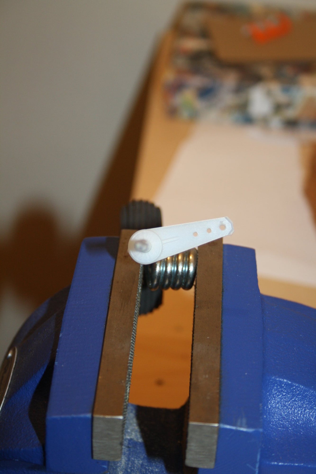
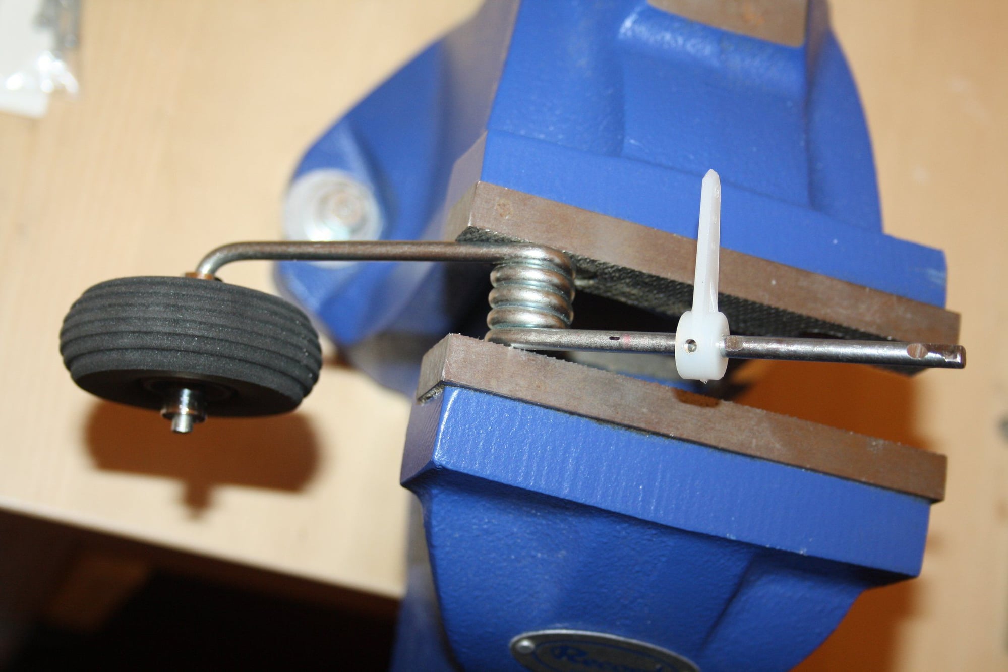
Finally, all was assembled, the rod was placed into a plastic sleeve and connected to the rudder servo.
Cheers,
Eran
09-06-2018, 03:34 AM
#89
Thread Starter
I also bought a different fuel tank to try and resolve the reach issue.
This idea was put on hold for the moment as the Du-Bro tank won't fit into the compartment without removing some material from the former.
Cheers,
Eran
This idea was put on hold for the moment as the Du-Bro tank won't fit into the compartment without removing some material from the former.
Cheers,
Eran
09-06-2018, 04:07 AM
#90
Looking good. Glad you found a solution without major surgery. It is all a tight fit on that airplane.
I might point out something in last picture post 88. I can�t tell from the picture, but make sure the steering rod EZ connector clears your wing. I moved some servos on a model and decided to use that type connector for throttle. I found the connector rubbed against the wing. I had to place the servo deeper into the fuselage.
I might point out something in last picture post 88. I can�t tell from the picture, but make sure the steering rod EZ connector clears your wing. I moved some servos on a model and decided to use that type connector for throttle. I found the connector rubbed against the wing. I had to place the servo deeper into the fuselage.
09-07-2018, 04:31 AM
#91
Thread Starter
ETpilot - Thank you for your reply. No problem in this case with the clearance to the wing. My servos touch the top of the fuselage which leaves a 1.5mm gap to the wing for the EZ screws.
I got the engine installed and set up the throttle servo. On installation of the spinner I realised that the back-plate is too thick leaving no threads for the prop nut. I will have to attend to this later.
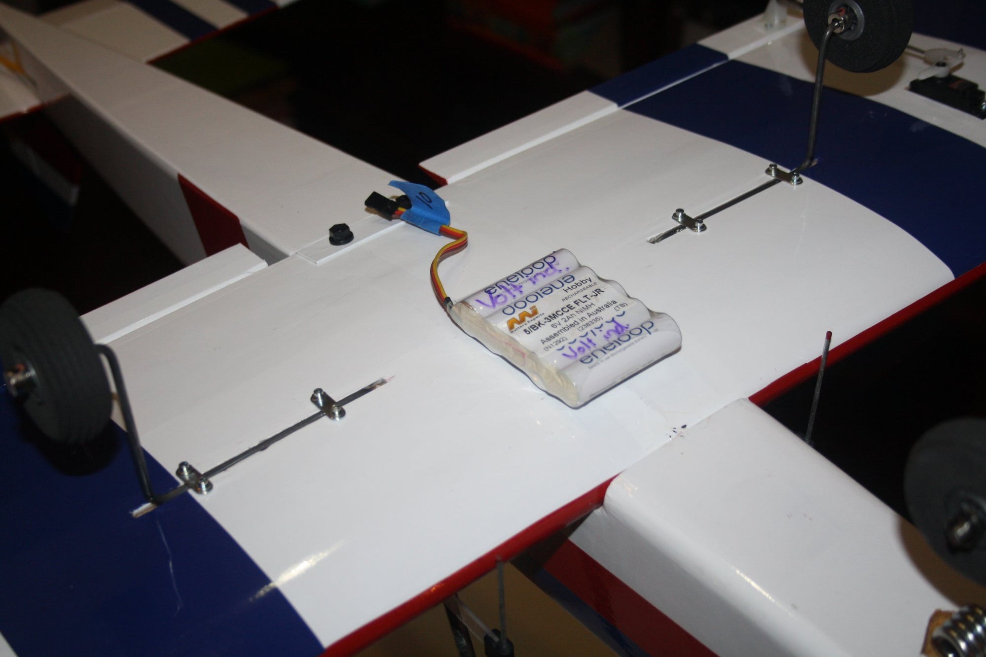
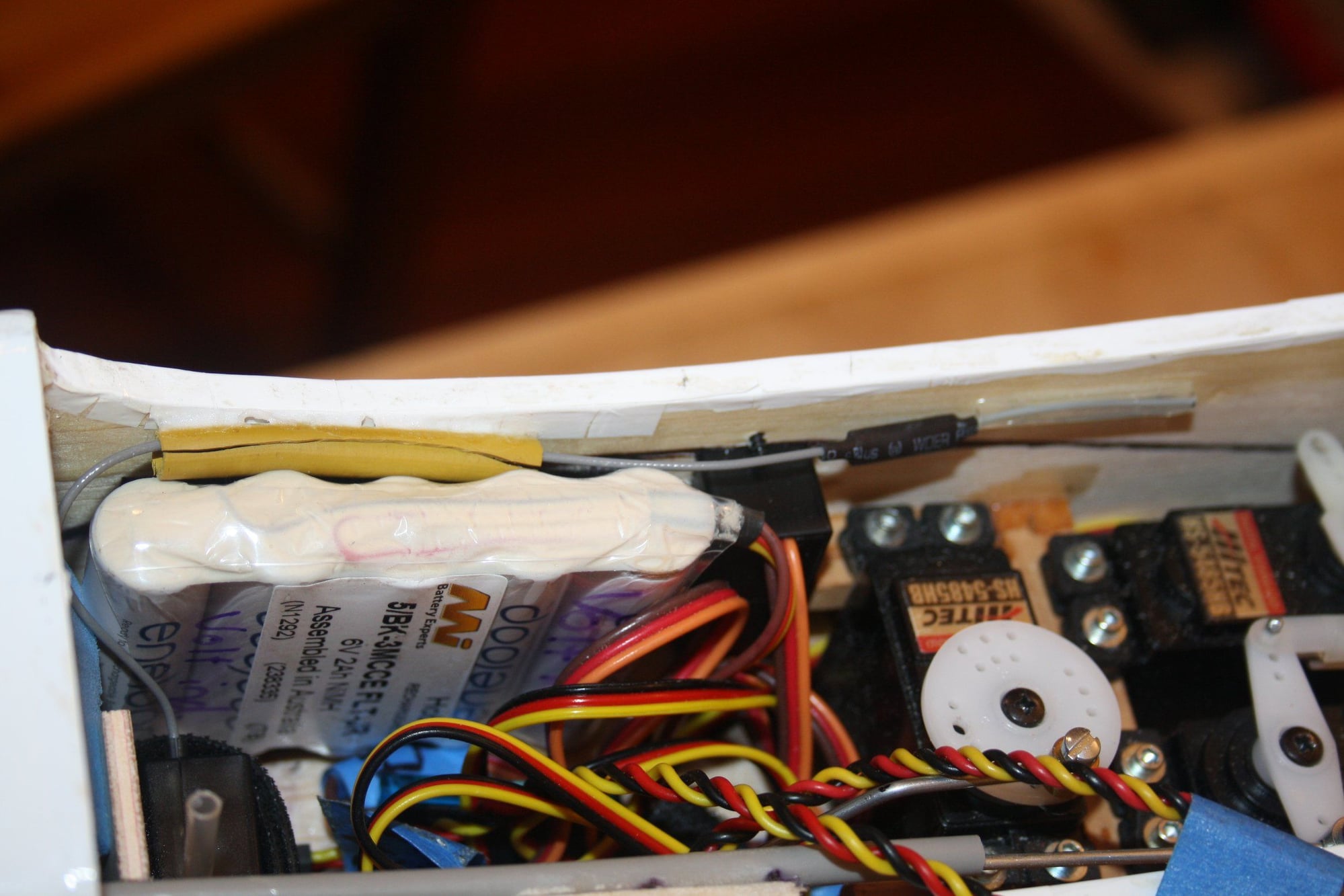
I installed the fuel tank encased in foam, and then did a quick CG check to figure out rough battery location.
Again, due to the amount of photos I will post additional thread...
Cheers,
Eran
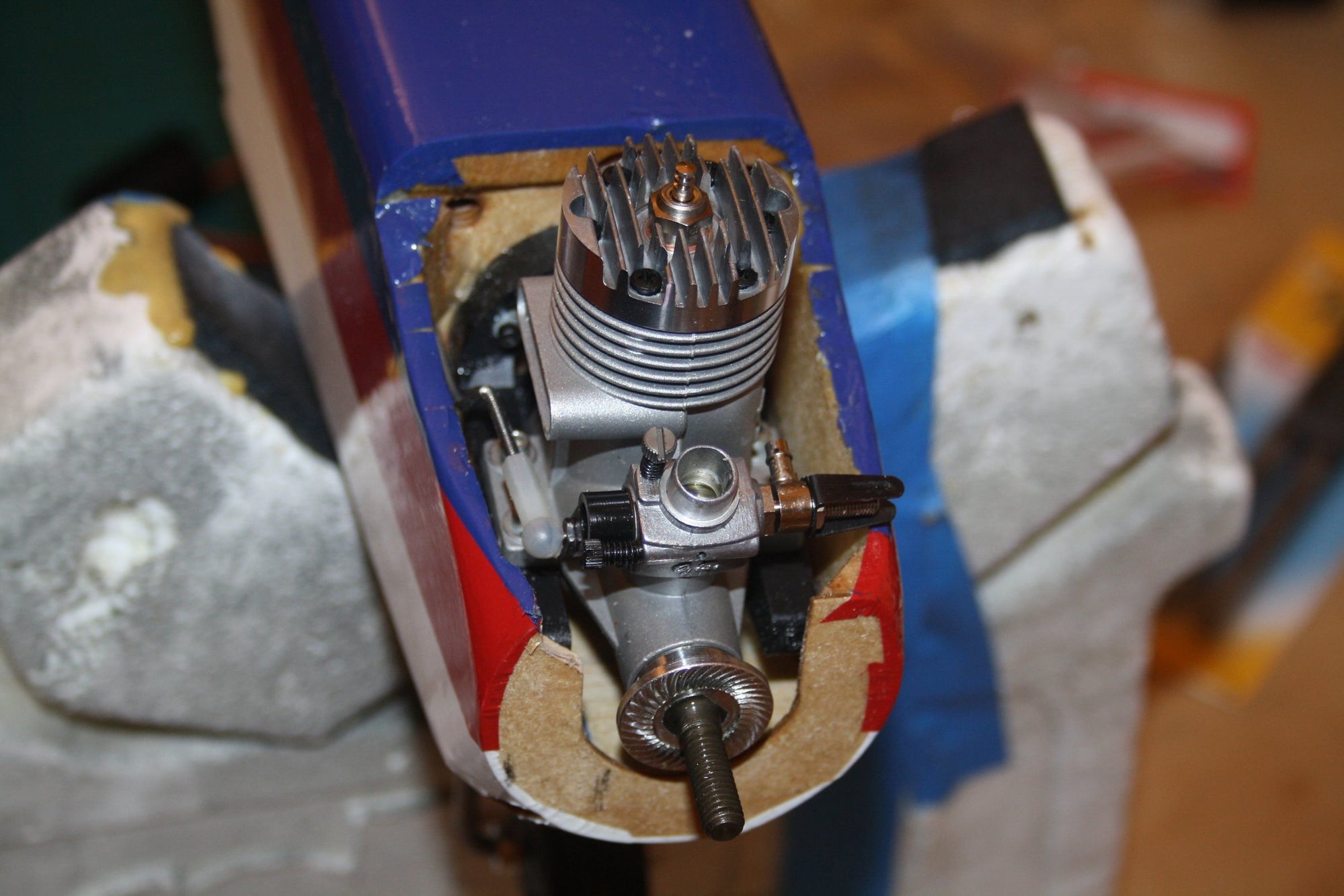
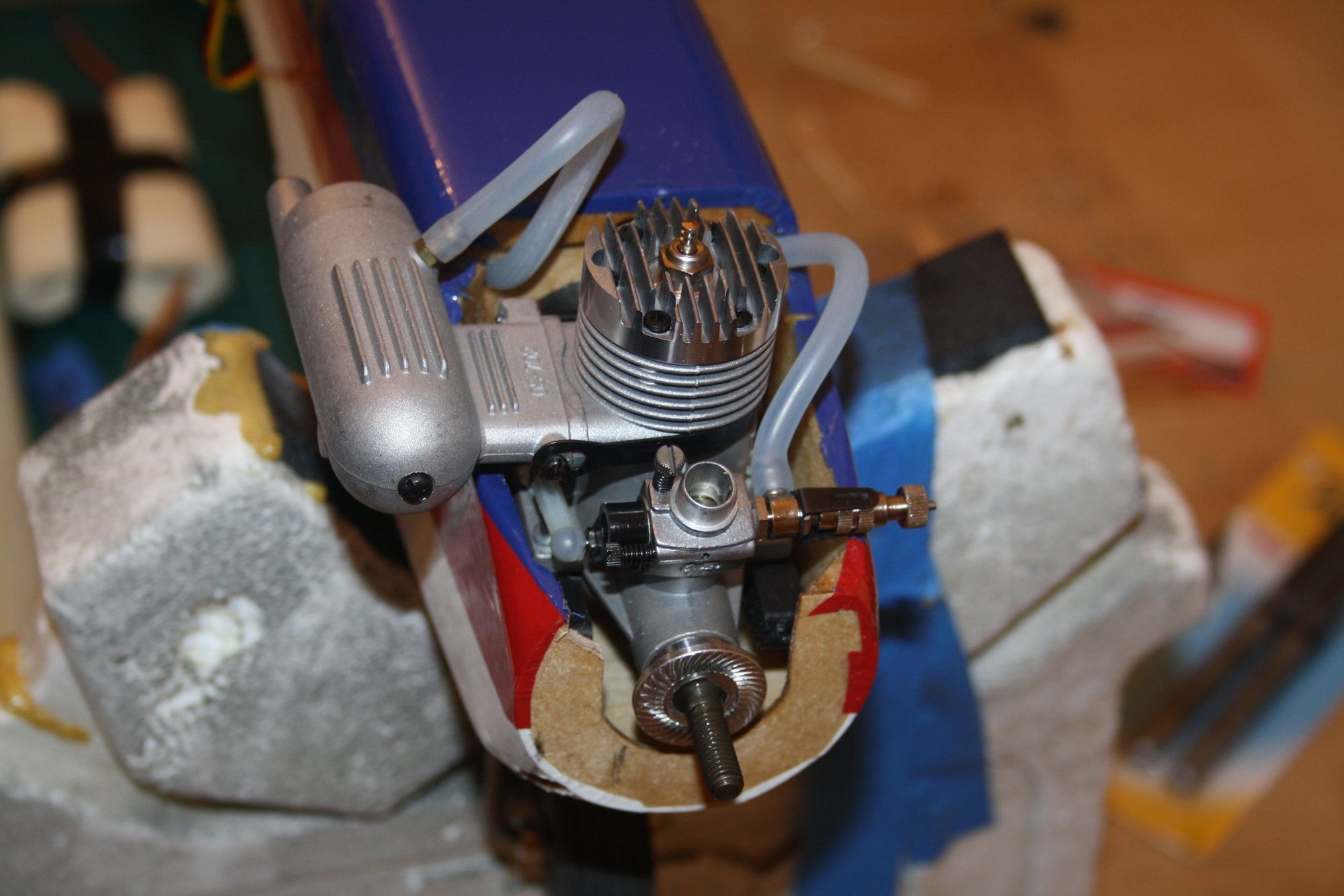
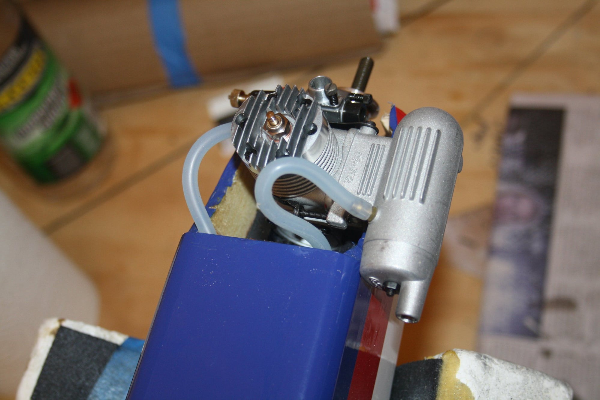
I got the engine installed and set up the throttle servo. On installation of the spinner I realised that the back-plate is too thick leaving no threads for the prop nut. I will have to attend to this later.
I installed the fuel tank encased in foam, and then did a quick CG check to figure out rough battery location.
Again, due to the amount of photos I will post additional thread...
Cheers,
Eran
 09-07-2018, 09:34 PM
#93
Thread Starter
Last push to get the New Era III out of the Cave. Again the photos will be placed over two threads
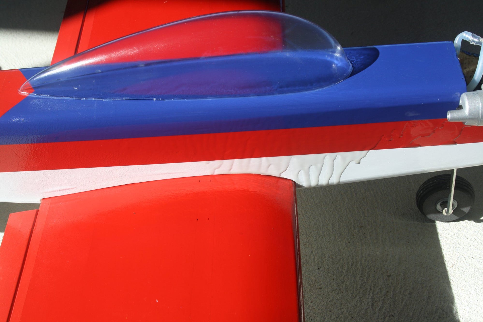
The canopy was glued into place;
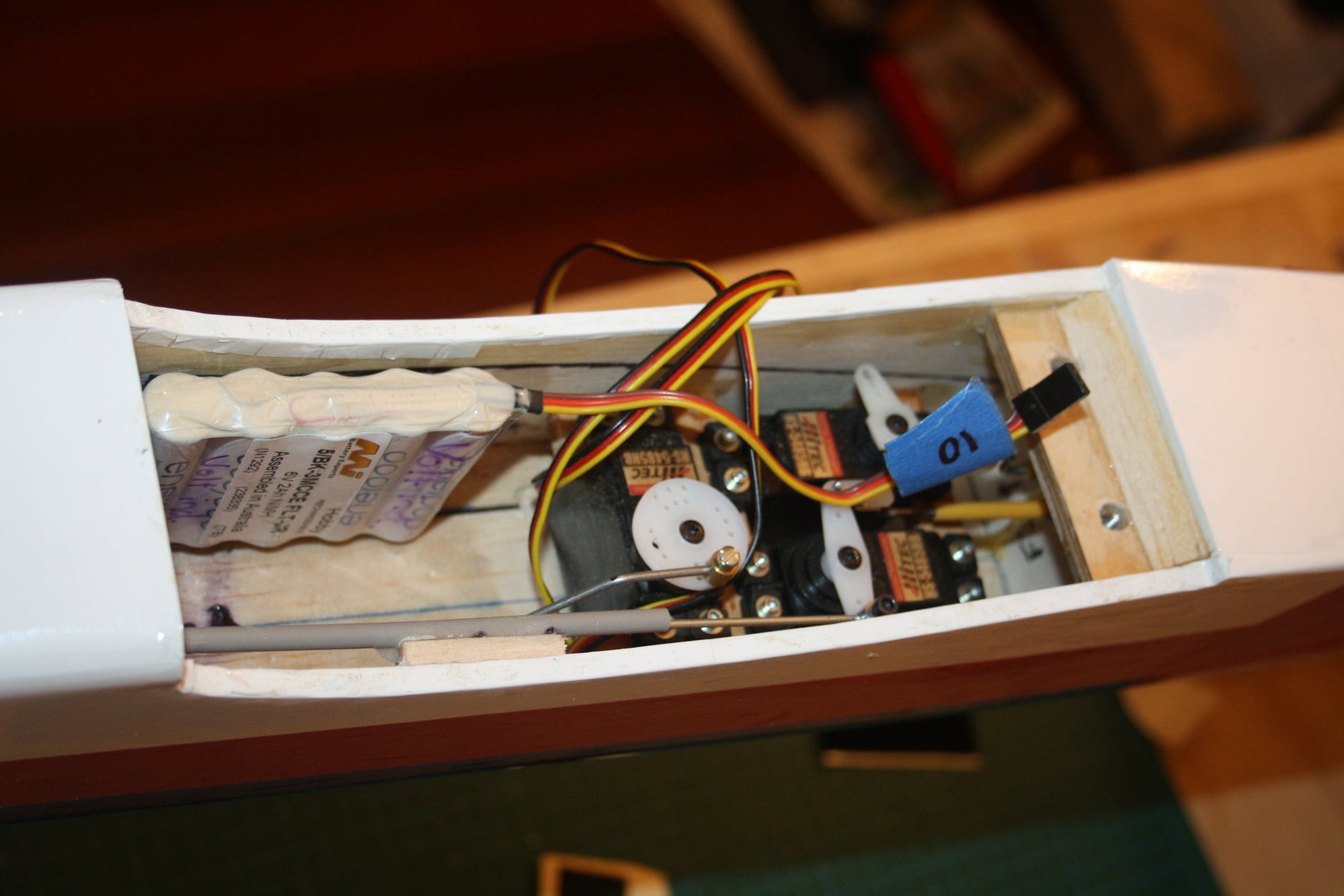
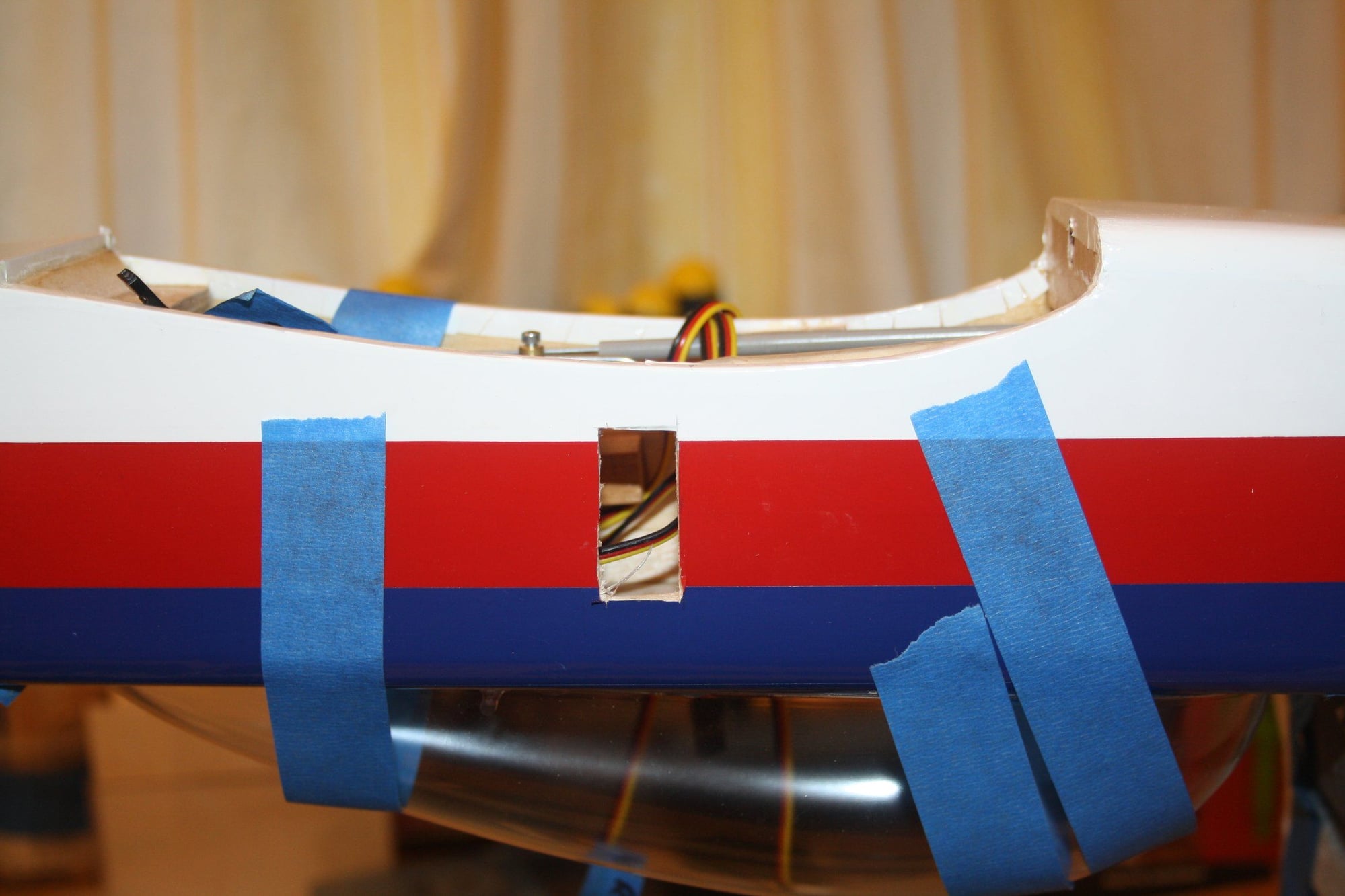
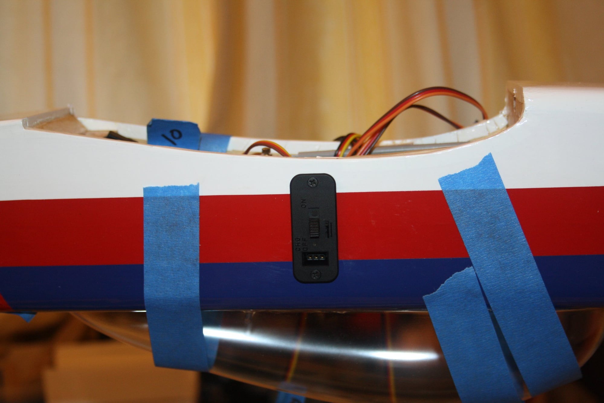
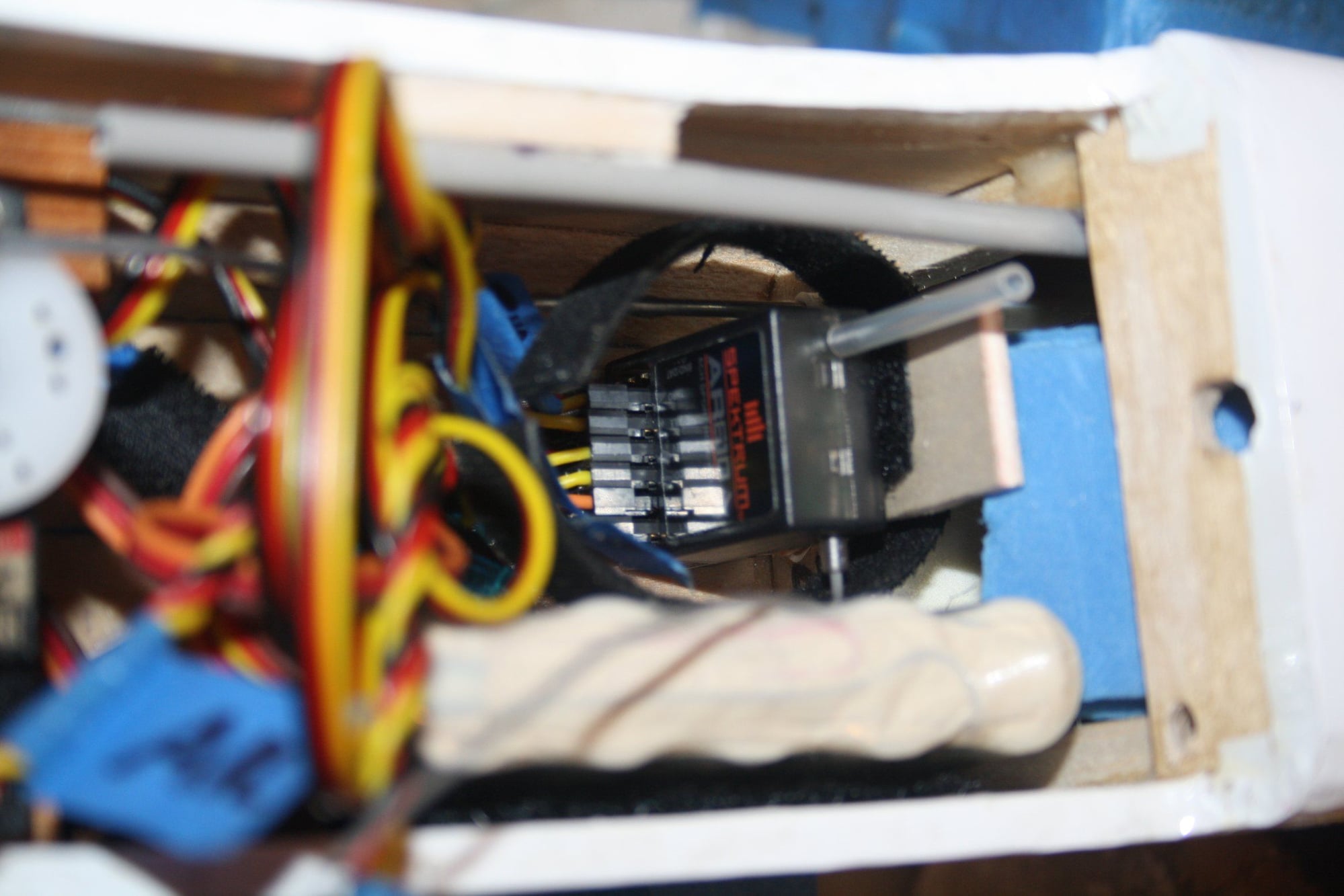
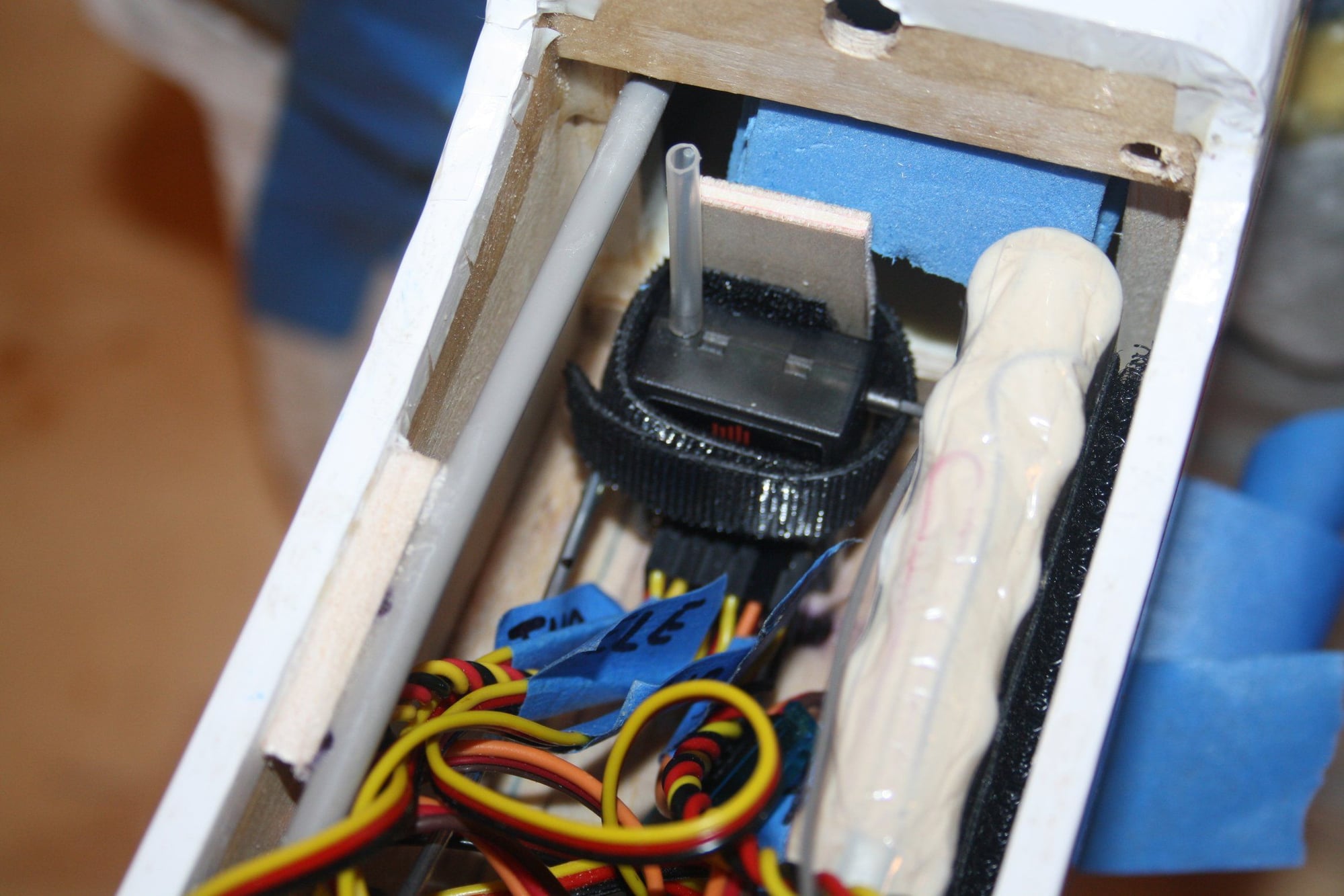
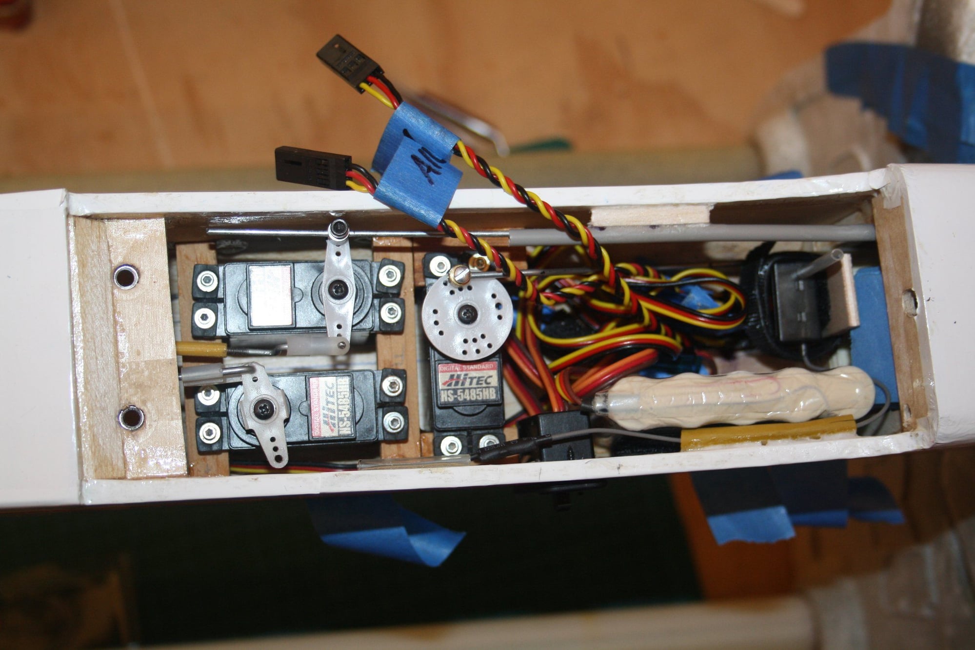
The Switch and Receiver were placed in the remaining space. It took a while to find a good place for the receiver which will allow diversity with the antennas orientation.
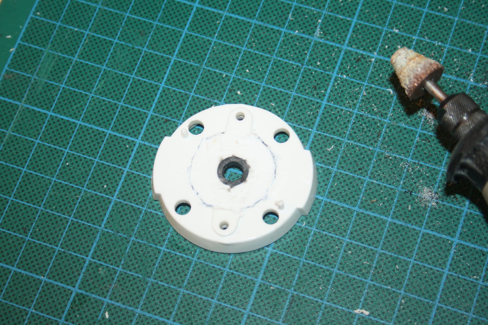
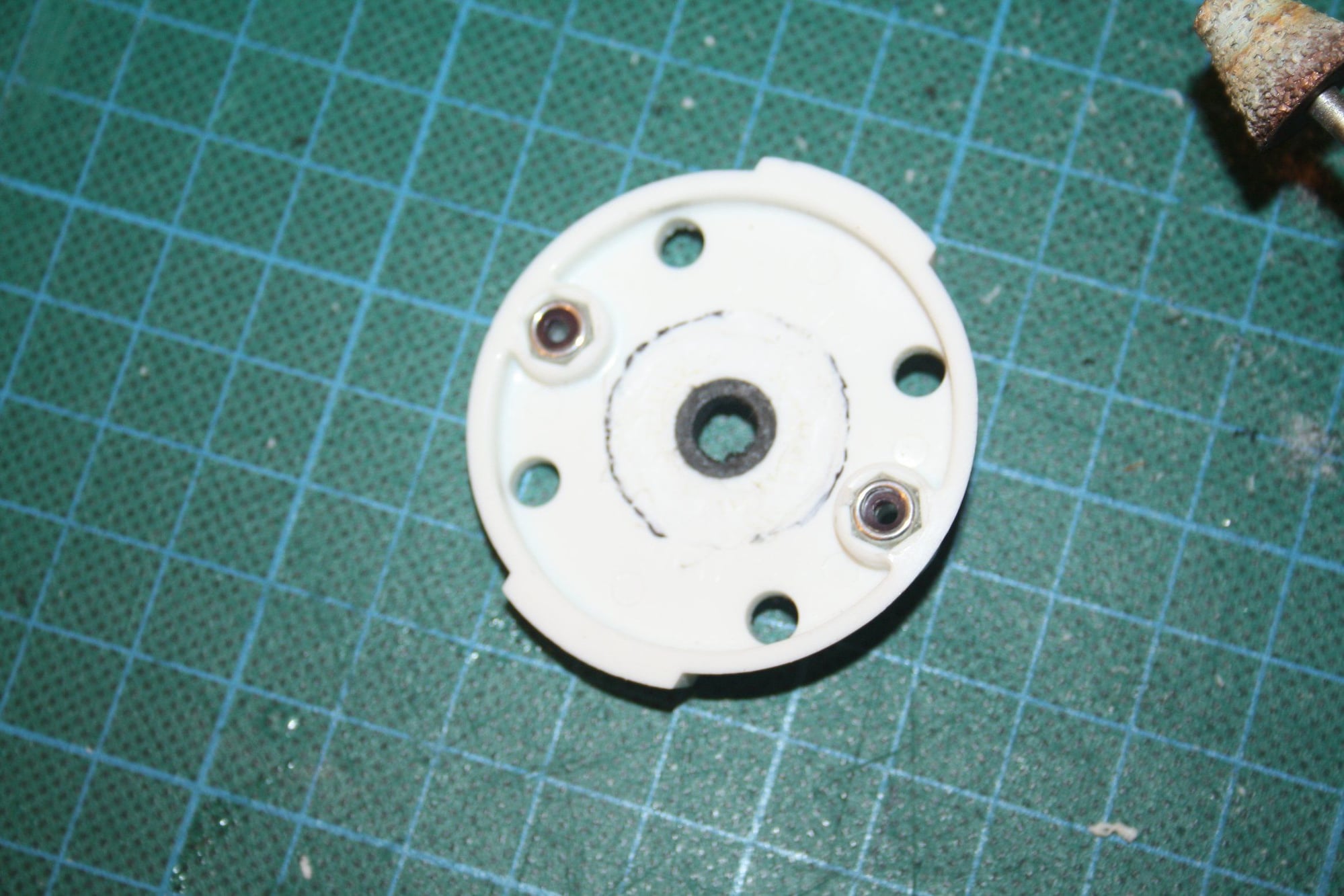
Then I removed material from both front and back of the spinner back plate to allow for additional the prop nut threads. I will probably figure out tomorrow if I was successful...
The aeroplane balanced perfect front to back, but required 10g at the right wing tip.
Hopefully at the very least I will get the engine run tomorrow,
Cheers,
Eran
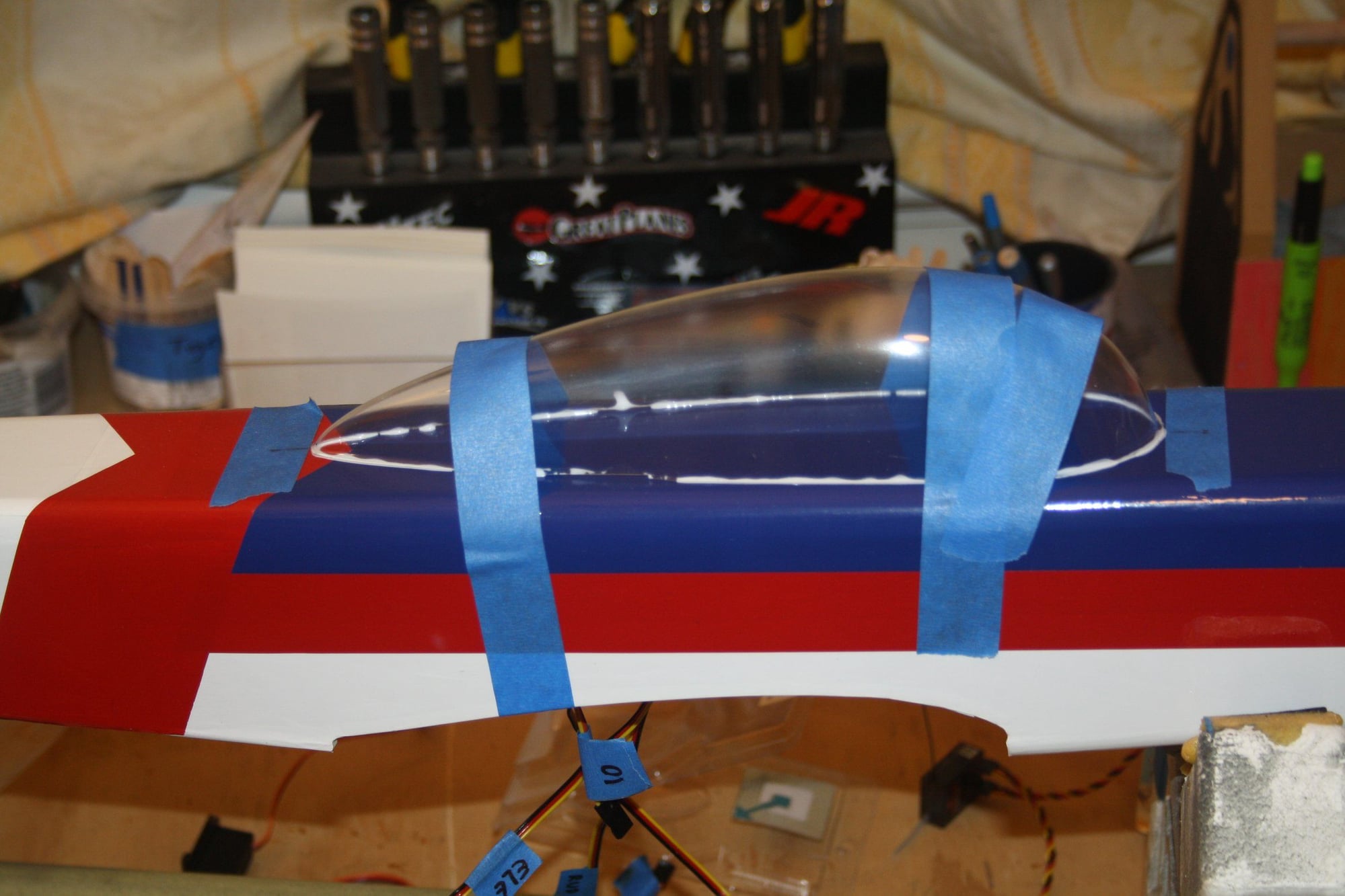
The canopy was glued into place;
The Switch and Receiver were placed in the remaining space. It took a while to find a good place for the receiver which will allow diversity with the antennas orientation.
Then I removed material from both front and back of the spinner back plate to allow for additional the prop nut threads. I will probably figure out tomorrow if I was successful...
The aeroplane balanced perfect front to back, but required 10g at the right wing tip.
Hopefully at the very least I will get the engine run tomorrow,
Cheers,
Eran
 09-09-2018, 02:21 AM
#96
Thread Starter
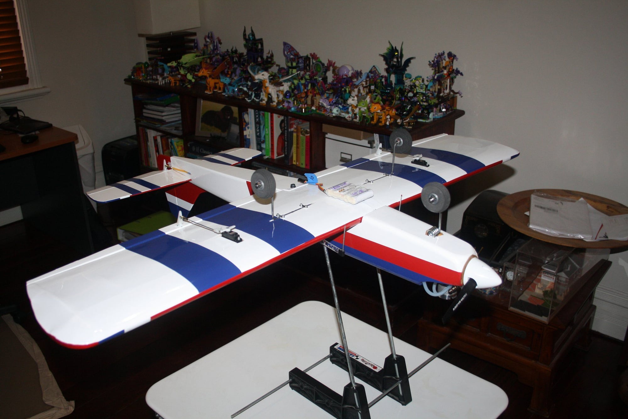
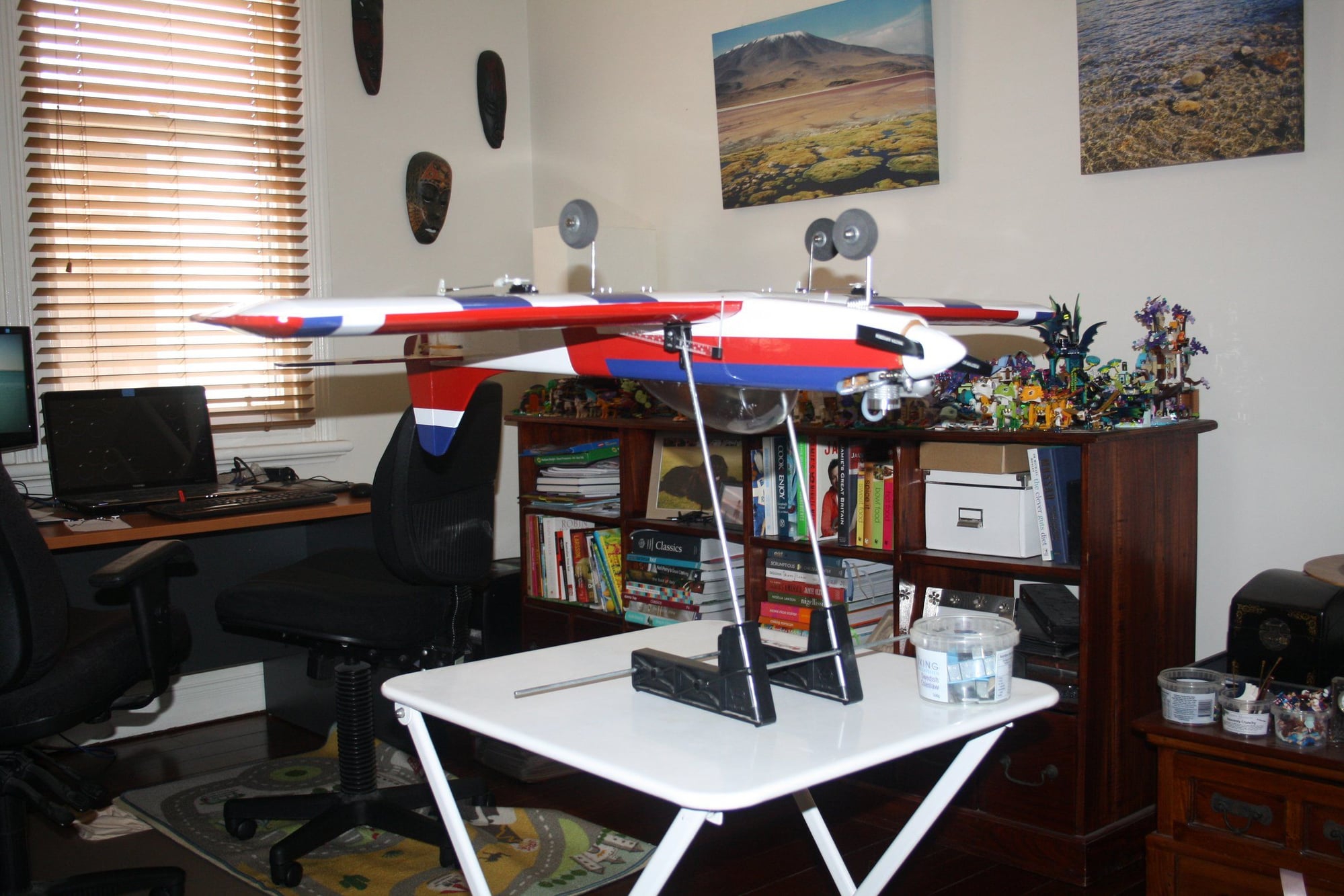
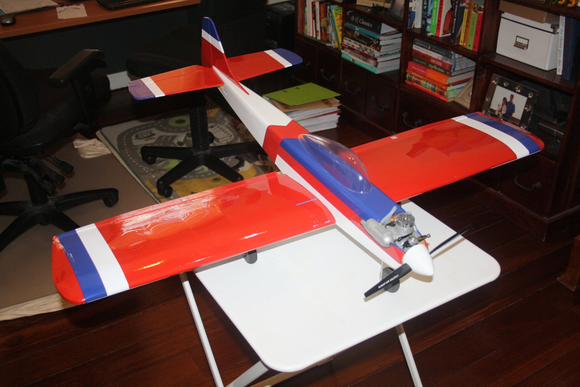
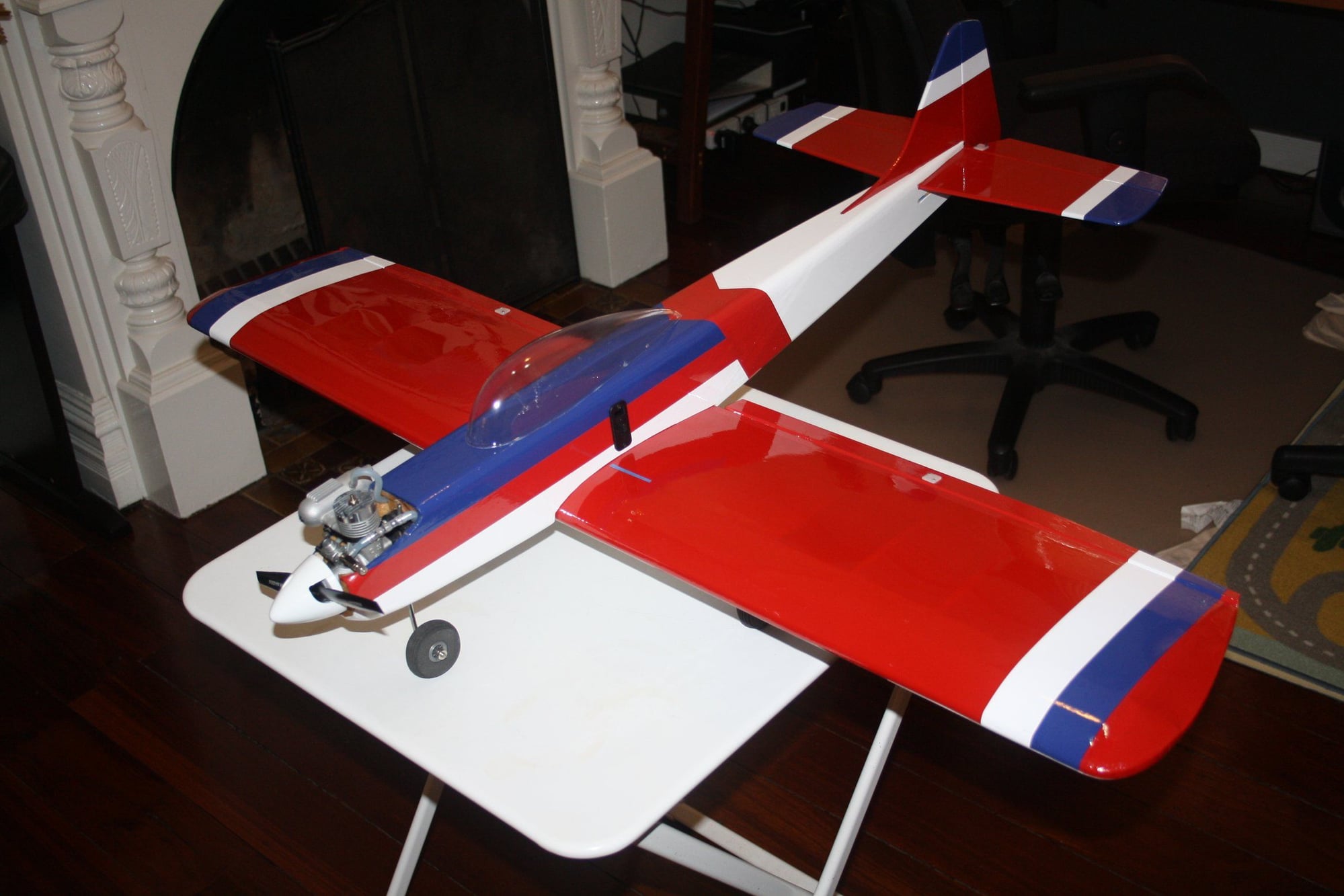
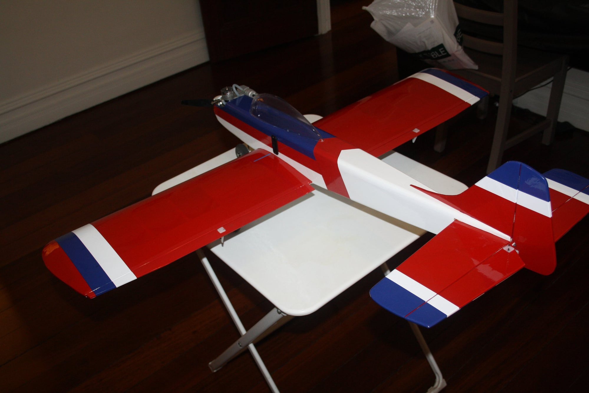
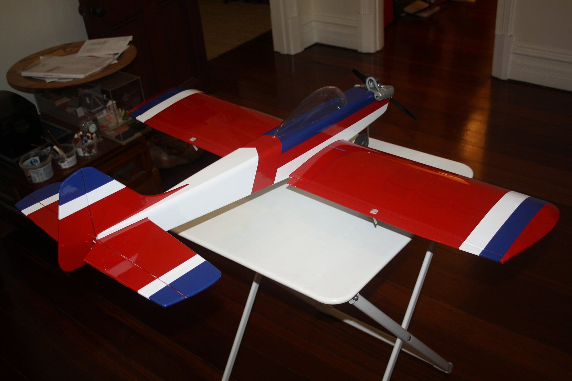
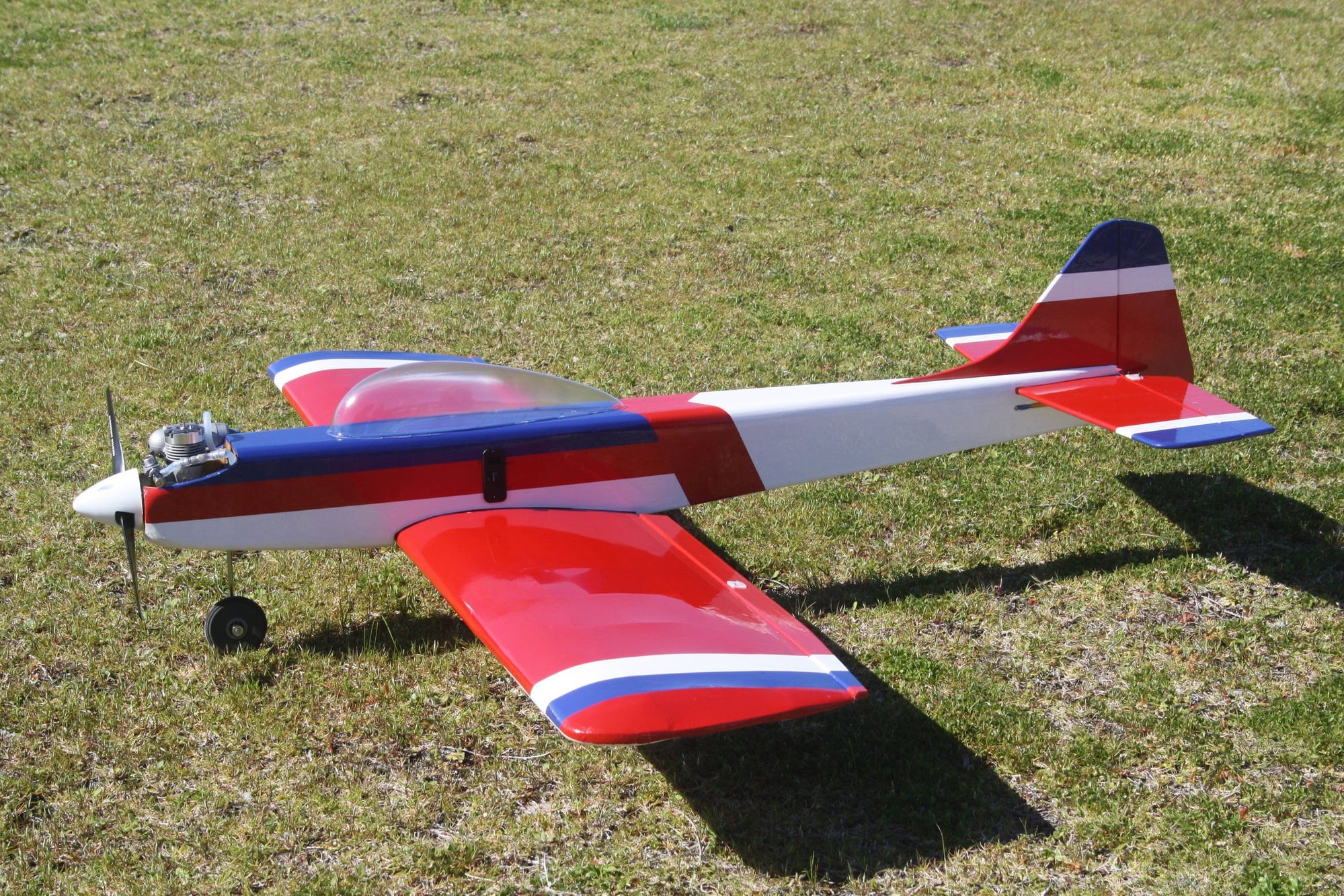
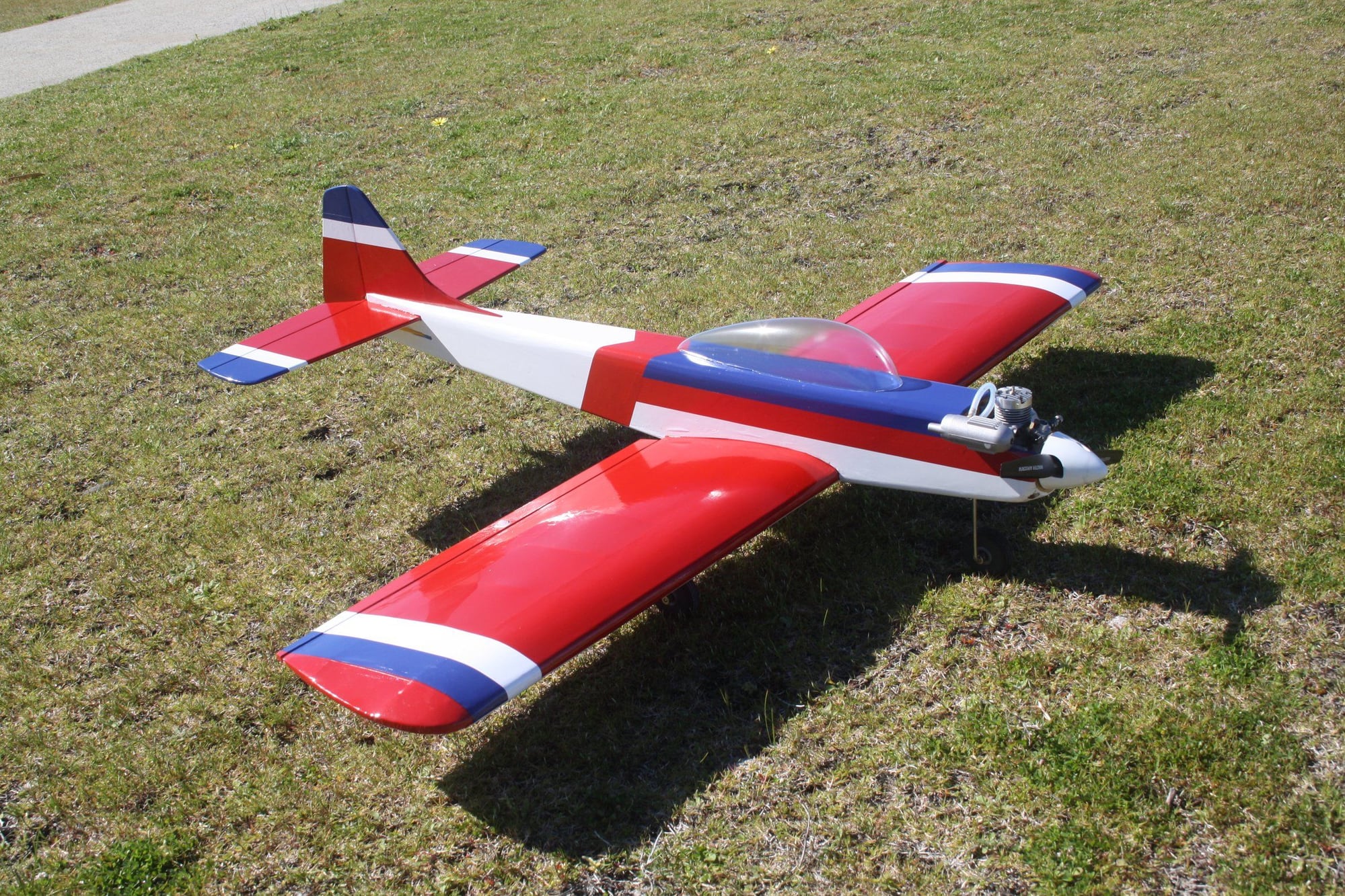
The New Era III project came to a very successful conclusion today.
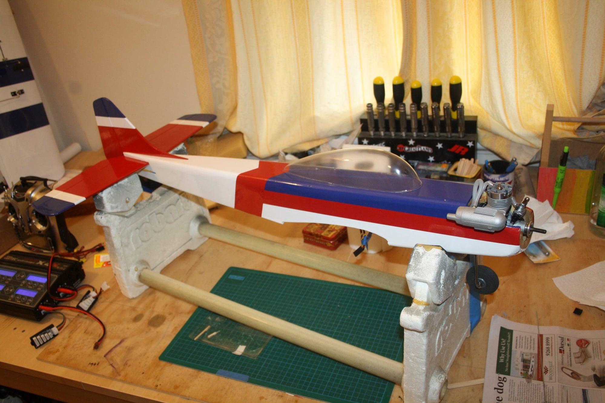
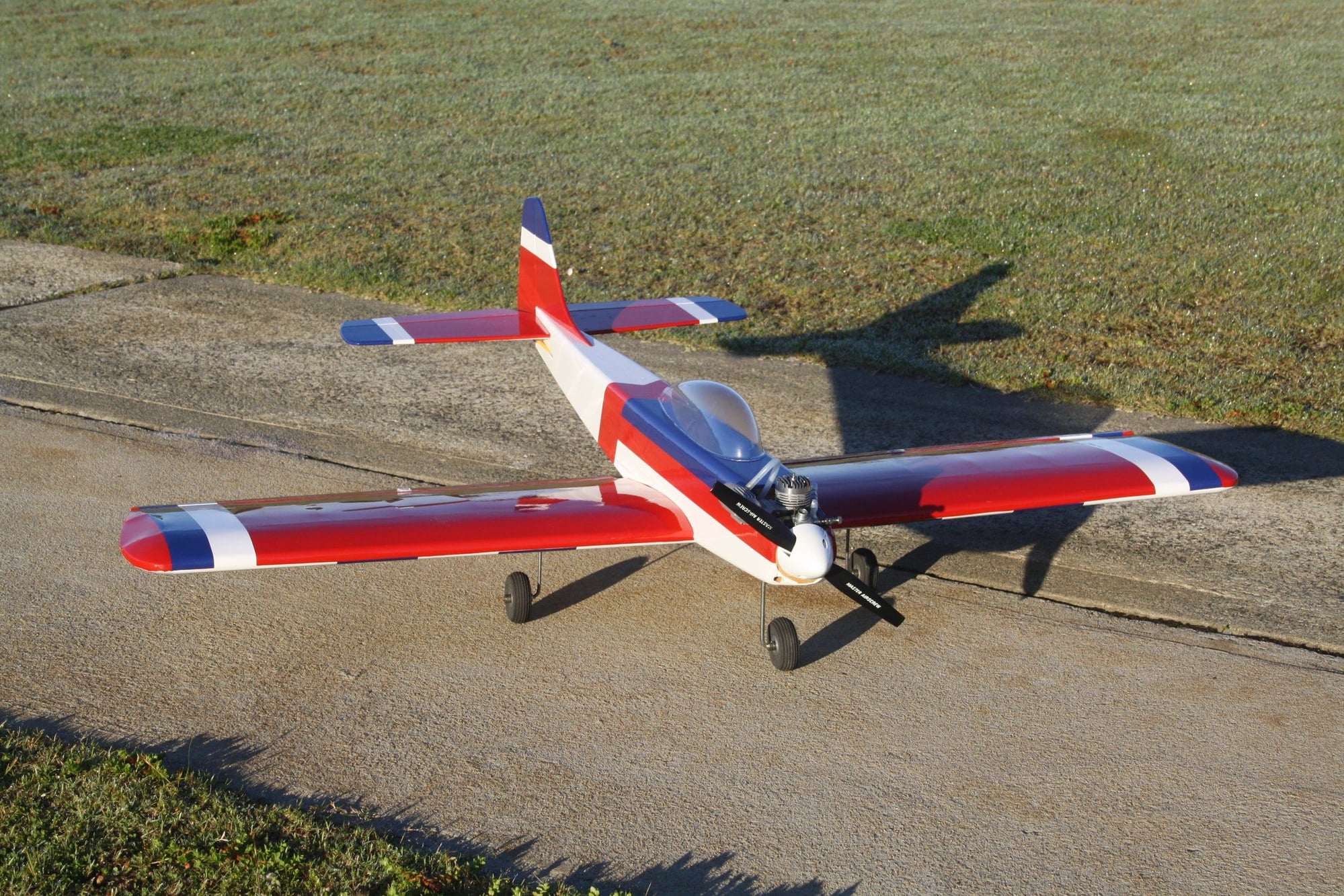
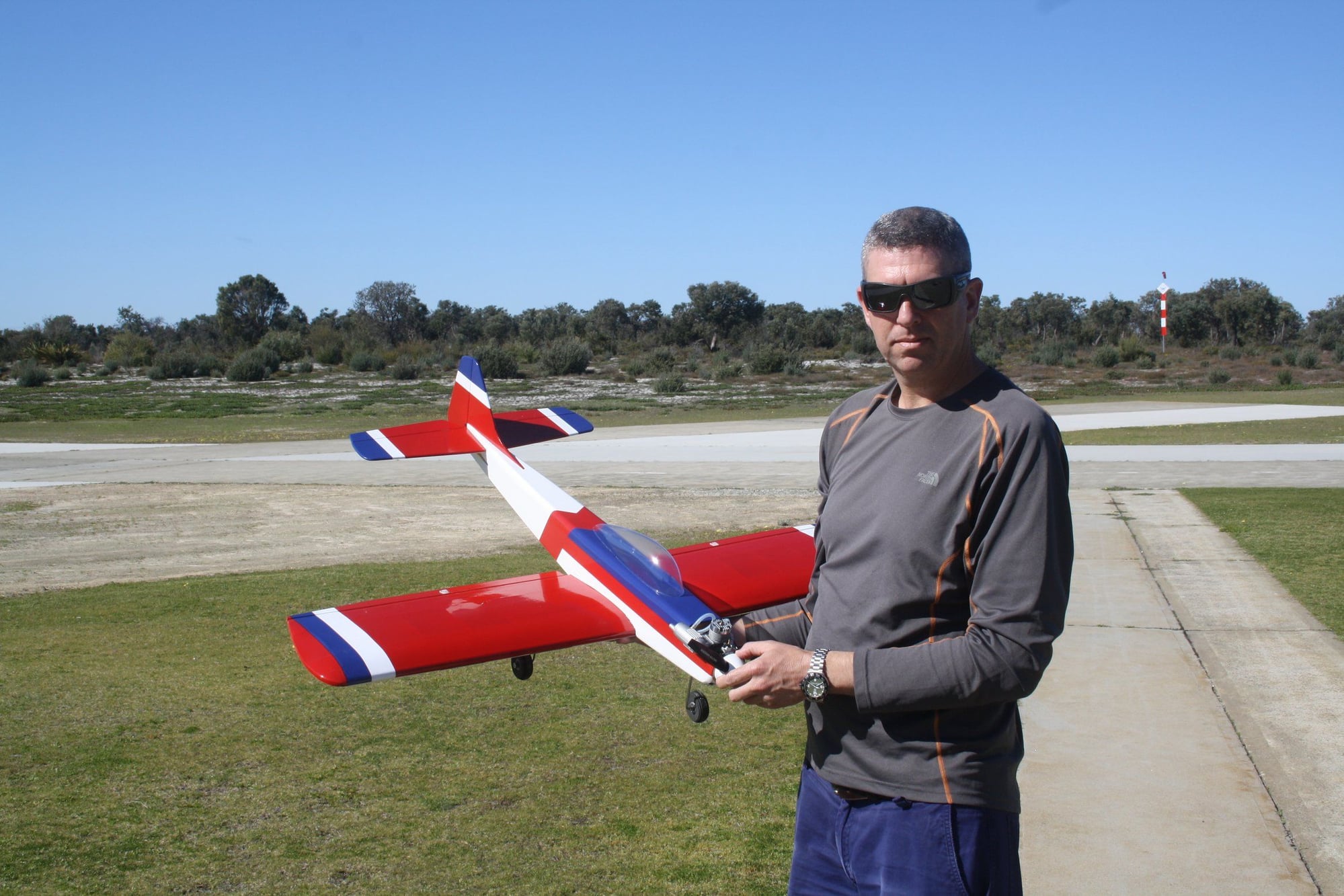
After the obligatory photos were taken, I placed the aeroplane on the starting stand for the first engine start of this brand new O.S. 20RC (which is over 50 year old).
On the third flip of the prop it started and it run beautifully. The manual stipulate 30 minutes run-in, however, after 10 minutes it was running so good I decided to run it in the air.
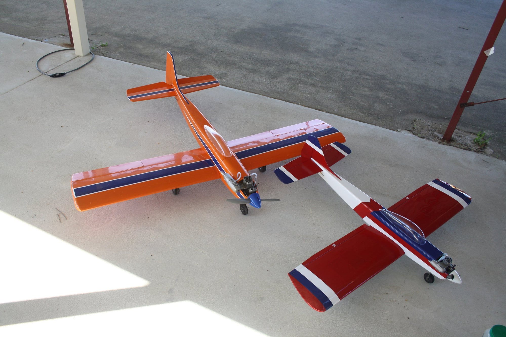
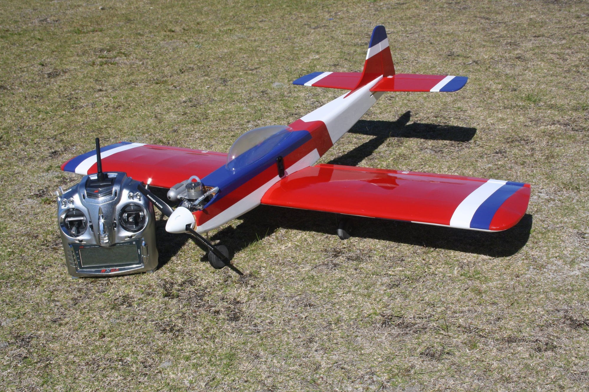
The maiden flight was uneventful, and after few clicks of trim it was flying great. A bit over sensitive on the ailerons, but an easy fix. I didn't perform any aerobatics yet as I was running the engine, but it seems to have enough power and control authority. Unfortunately I have no flying photos as my camera do not have suitable lens to capture such a fast small object. I only managed one flight with it today as it was at the end of my flying day (I did got few flights with the Kwik Fli III shown in the photos prior to this).
I am happy to say that I was proven wrong today about old engines. I could not believe how well the engine performed, and this is while being run quite rich.
Cheers,
Eran
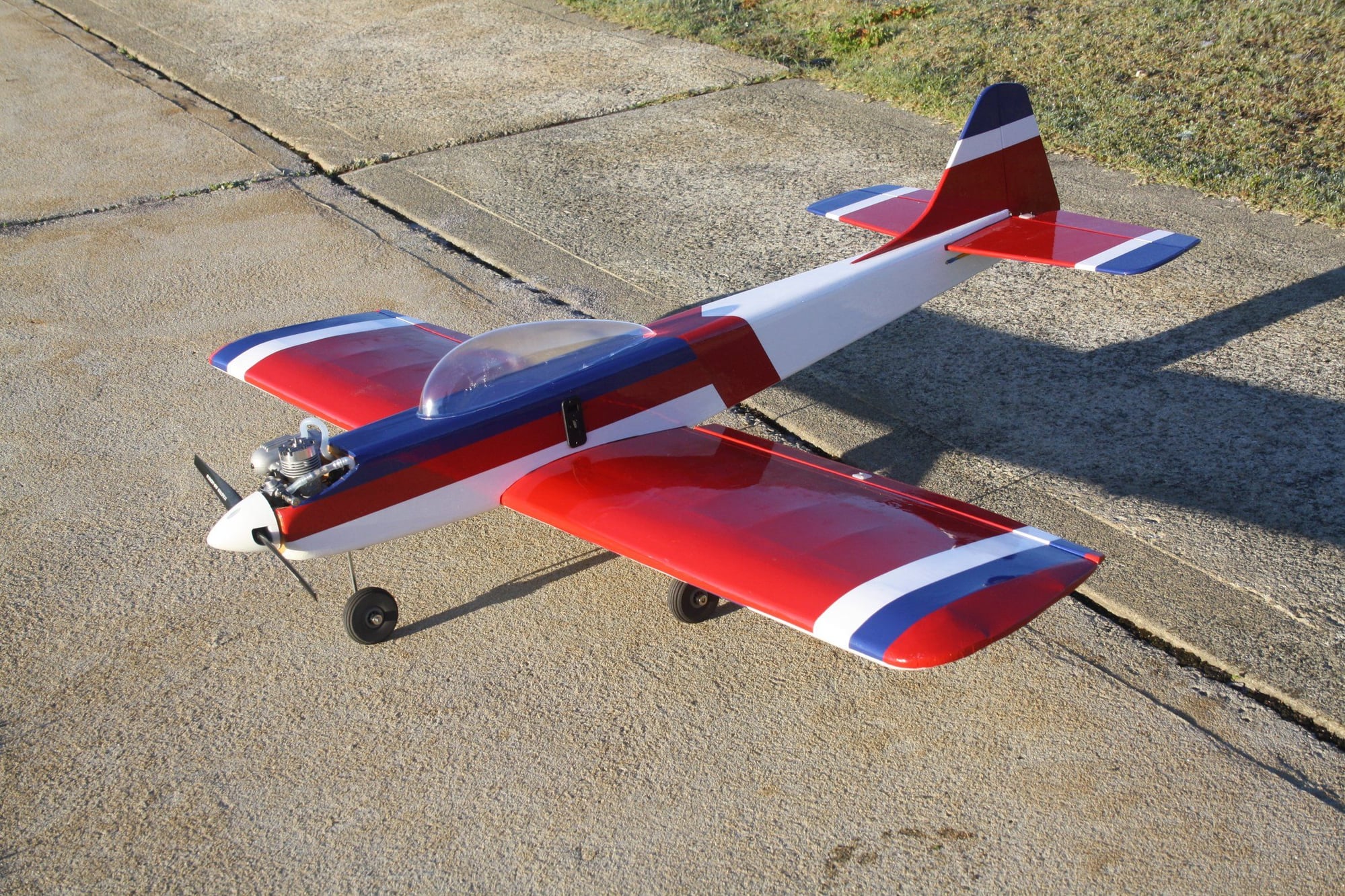
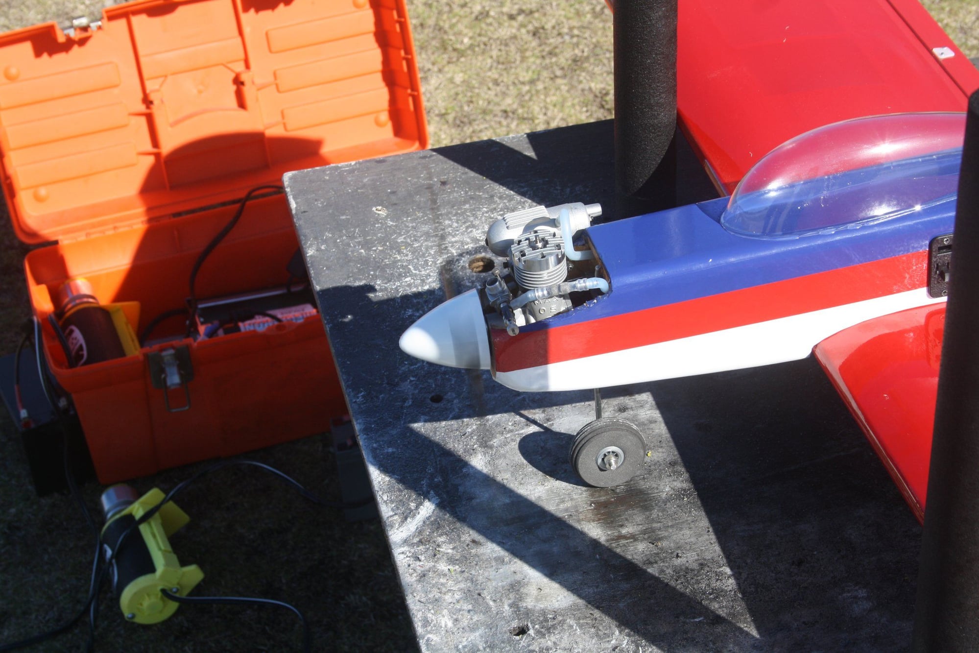
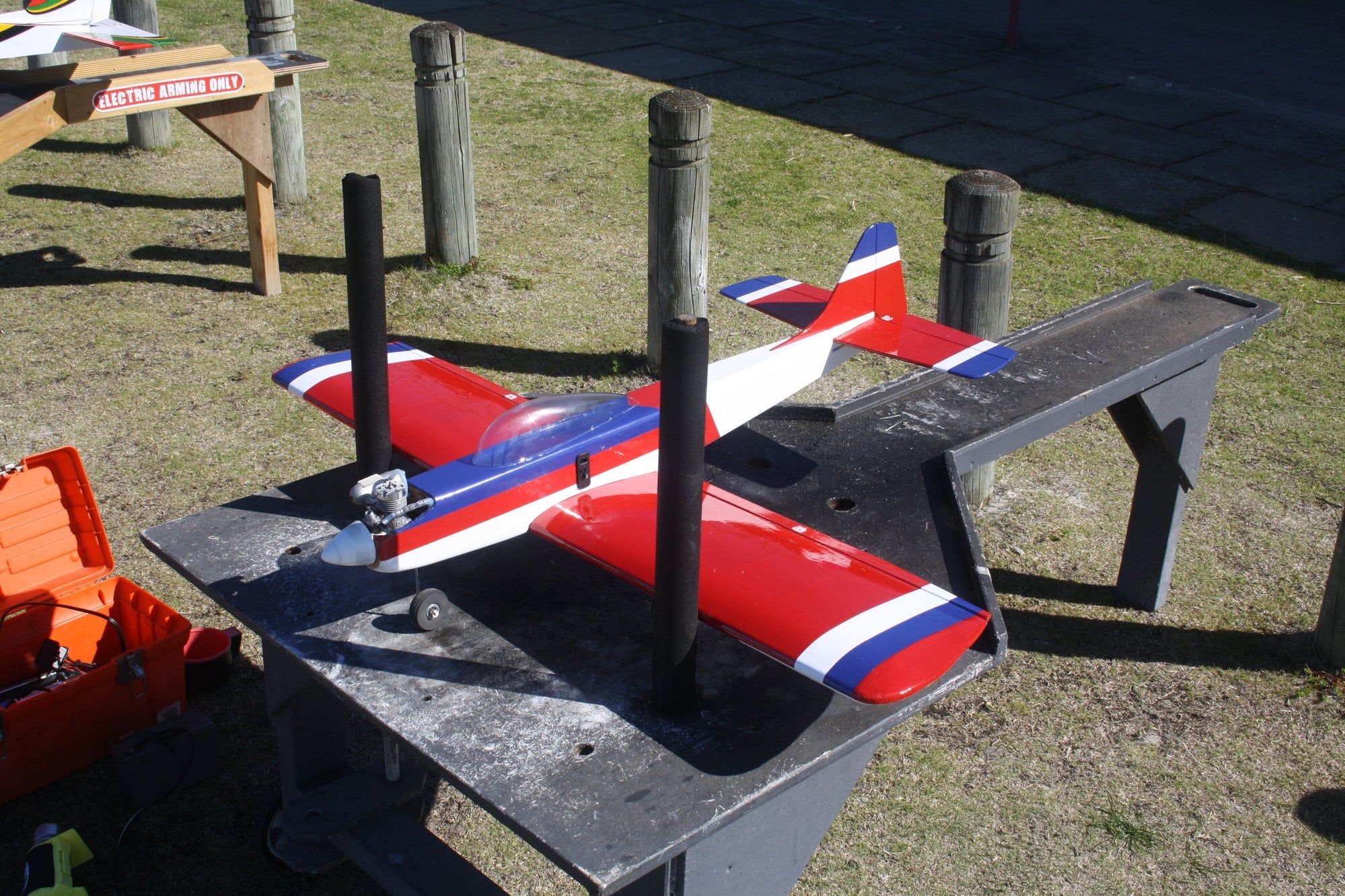
After the obligatory photos were taken, I placed the aeroplane on the starting stand for the first engine start of this brand new O.S. 20RC (which is over 50 year old).
On the third flip of the prop it started and it run beautifully. The manual stipulate 30 minutes run-in, however, after 10 minutes it was running so good I decided to run it in the air.
The maiden flight was uneventful, and after few clicks of trim it was flying great. A bit over sensitive on the ailerons, but an easy fix. I didn't perform any aerobatics yet as I was running the engine, but it seems to have enough power and control authority. Unfortunately I have no flying photos as my camera do not have suitable lens to capture such a fast small object. I only managed one flight with it today as it was at the end of my flying day (I did got few flights with the Kwik Fli III shown in the photos prior to this).
I am happy to say that I was proven wrong today about old engines. I could not believe how well the engine performed, and this is while being run quite rich.
Cheers,
Eran
09-09-2018, 04:06 PM
#99
I ran in to the same problem with the steering arm, I solved it by installing the bracket in the rear of the firewall and opening a hatch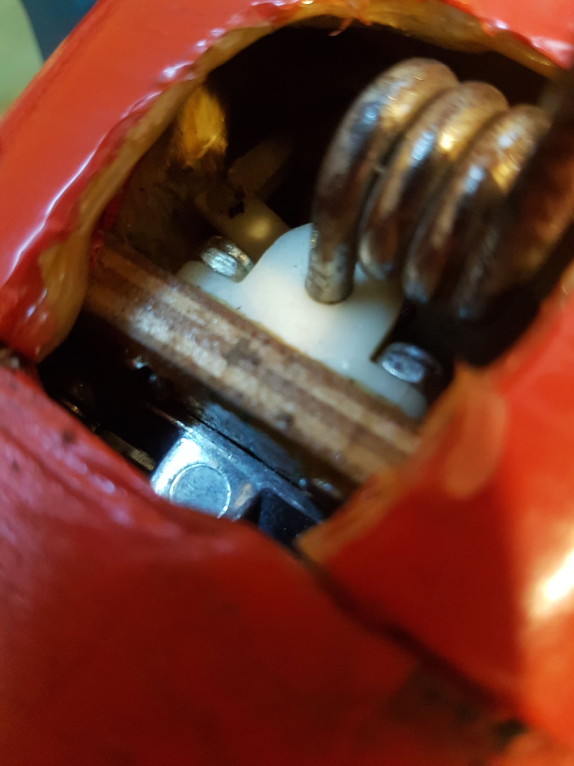
on the lower part of the nose.
on the lower part of the nose.
