


Flaps with aluminium's pieces
 07-26-2020, 11:42 AM
#26

My shop is large but very cluttered. A trip hazard at times. I’m working on a foam profile airplane. Today I hot wired the foam sheets thinning to 1/2” thick. I have some very thin foam sheets looking up at me.
I've only looked at the plans. Didn’t know of nor checked for an article. Will check it out.
I've only looked at the plans. Didn’t know of nor checked for an article. Will check it out.
 07-26-2020, 12:20 PM
#27
Well, I’ve looked for that article but cannot find it. The link for the plan only lets me download the plan. No article attached. I can’t find a separate link for an article. Can you provide a link for the article. The plan doesn’t have any reference regarding bottom sheeting. It does show a fuel tank bay hatch and a radio bay hatch but no reference as to hatch thickness.
07-27-2020, 01:09 PM
#28

Thread Starter
The Pharaoh's plane is the worst plane I've ever come down. Measurements of wood are missing or incorrect, some wrong instructions and worse, the slots in the trainers are completely misaligned and poorly drawn. I will have to make many corrections to continue, since I already glue many of the pieces. I'll send you the magazine´s article.
07-27-2020, 04:17 PM
#29
Unfortunately, you sometimes get plans with missing or incorrect information. Reviewing the plan I can see where some additional info is needed.
Just problems we need to work out. I just downloaded the article and will review. Thanks.
Just problems we need to work out. I just downloaded the article and will review. Thanks.
07-27-2020, 06:05 PM
#30
Just some points. Regarding the flaps pictured in the article shows the optional flap cover plate installed. You still get the open gap for the flaps. I pointed that out earlier.
Bottom sheeting starts at F3 and is installed cross grain. Will be strong. Forward of F3 you have the radio hatch and fuel hatch. The plan doesn’t show the bottom sheeting. So if you build per the plan as pictured and then install the bottom sheeting you will have a step between the bottom sheeting and the hatch. Plan to install the hatch so it is even with the bottom sheeting.
In the pictures posted in post # 23 the top picture shows the top formers F4-F7 the proper size. In the bottom picture, fuselage in jig, those formers after F3 look short. Should be a gradual incline form F3-F7.
I’m not understanding what you mean regarding “the slots in the trainers are completely misaligned....”
 07-28-2020, 05:13 AM
#33
I’m going to print the article, your text message and plans as I’m going to different areas on iPad to gather information.
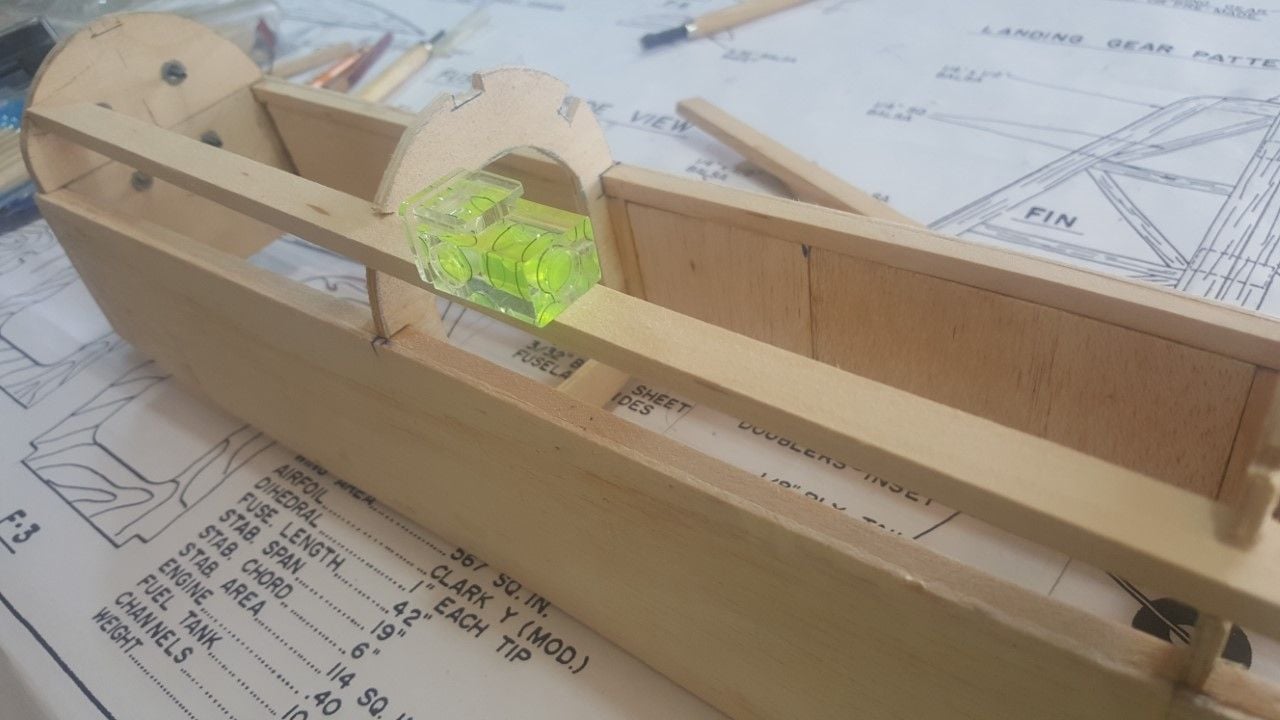
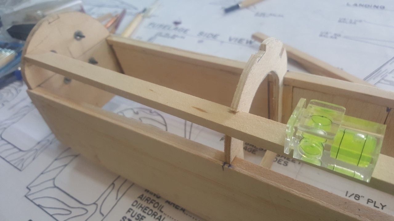
That hardwood piece runs parallel with longeron that supports side sheeting. There should be no inclination. Under the hardwood square are plywood pieces to help support the wing struts. Also hardwood and plywood would be glued to top sheeting and formers. Should be strong. The wing struts should be bolted at that location. With wing removable hardware above. Not a lot of info there. Anyway I’ll study it more with the paper prints.
These are problems you get with scratch building. Sometimes you have to improvise. I sometimes make cardboard templates to check things out.
Cardboard landing gear.
07-28-2020, 04:21 PM
#34
Ok, I’ve printed the documents. Much easier to work with paper rather than the iPad.
The hardwood wing strut support pieces run parallel to the fuselage sides which you have figured out. One way to check this is measure the distance from top of longeron to bottom of hardwood support. Cut 2 pieces of wood to this height and long enough to span from one side of the airplane to the other side. Place these pieces one by F1 and one by F3 across the fuselage. Place a straight edge on top of these pieces and mark your formers. This mark will be the bottom of the hardwood support. Doing it this way will be equal spacing on both sides of the fuselage. From that mark you can measure for the notch in the former. You may have to plane the outside edge of the hardwood to follow the curve of the formers. Any cuts you now have in the former that do not line up can be filled in with a glued in piece then properly cut the notch. You can reinforce, if needed, with a gusset glued on three sides of the hardwood and glued to the back or front of the former. On the bottom of the hardwood support you will glue in the plywood wing strut attach plates. The bolts go through these plywood plates and hold the wing struts. These bolts do not go through the hardwood supports.
You can do the same to the formers F4 to F7. Add gussets if needed. I agree that the leading edge of the wing requires a Ľ by ľ or ⅞ piece. The Ľ” square you are seeing may be the pieces needed to install the leading edge wing slat.
07-28-2020, 05:45 PM
#35
Thread Starter
Hello, thank you for your comments.As all the formers and spars were glued, I made again the wall of fire that I did not yet install, I made the right notch in the right place and subsequently I will expand the slot in F2 and F3, so that the lengths run horizontally and parallel and the aluminum supports of the wing are in the correct position with the rest of the wood that marks the plane. The mistake was annoying but when you have experience, it's easier to fix those details. With the F4 to F7 formers, as they're also attached to the fuselage, I'll do the same. I mean, I'll level each slot so the spars run straight. It happens as with women, who once dressed, no one imagines how bad they bring under the clothes, in this case, of the monokote.
___
___
08-01-2020, 04:53 PM
#36
Thread Starter
Hello. I began to fix the slots for spruce wood that will receive the aluminium struts. I will change them for 1/4 x 1/2 inch for add resistence. I have very care with level horizontal as vertical. Once that I have it, I'll make slots in fire wall and I'll glue it. I'll reforce the formers where they touch the longerous.
I am sending pictures about

this. I wait your comments.
I am sending pictures about
this. I wait your comments.
08-01-2020, 07:00 PM
#37
That looks good. Just measure the width of the wing struts. Then measure the width between the new strut support pieces. Make sure there is enough room for the wing struts. Going to 1/2” decreases the space.
08-02-2020, 03:15 AM
#38
One point about attaching pictures. Pictures get attached wherever the cursor is in your post. In your previous post the pictures are between the words “ about and this”. This means the cursor was between those 2 words.
I like to write the text then place the cursor 2 lines below the text. This leaves a space between text and picture. Sometimes you may want the pictures before the text. In that case place the cursor before the text. Hope you find this helpful.
I like to write the text then place the cursor 2 lines below the text. This leaves a space between text and picture. Sometimes you may want the pictures before the text. In that case place the cursor before the text. Hope you find this helpful.
08-02-2020, 04:52 AM
#39
Thread Starter
I find it very useful. I appreciate your information. The day you don't learn something new is a day lived in vain. My age is 78. What's your age?
08-02-2020, 08:56 AM
#40
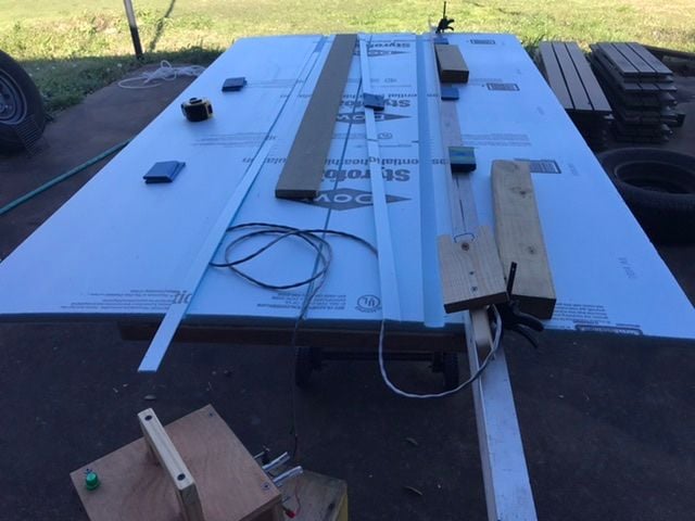
I am 77 years old. Feel like 19. Still learning. Working with foam now; new to me. Started cutting my first airplane yesterday. Even if it doesn’t work out, I will have learned something. I found out I need to make some new cutting bows and make changes to my vertical cutter.
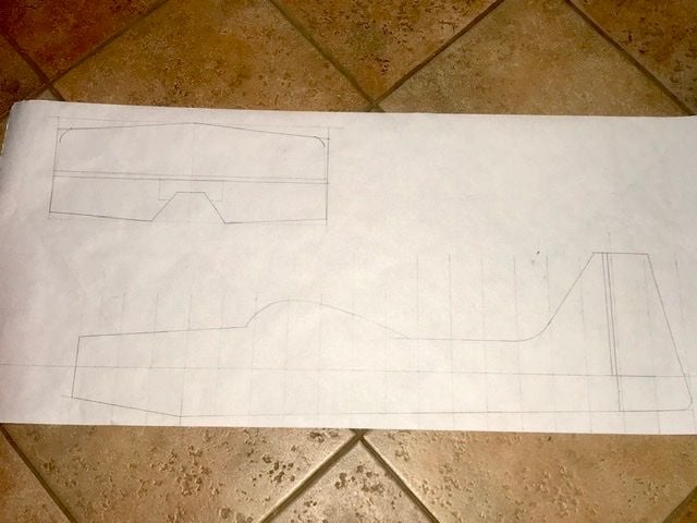
This will be a profile airplane. I’m working with 1/2” stock which I will cut down to 3/8 or 1/4 “. I cut some samples.
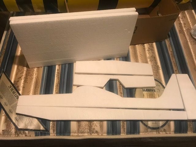
This will be a profile airplane. I’m working with 1/2” stock which I will cut down to 3/8 or 1/4 “. I cut some samples.
08-02-2020, 09:30 AM
#41
Thread Starter
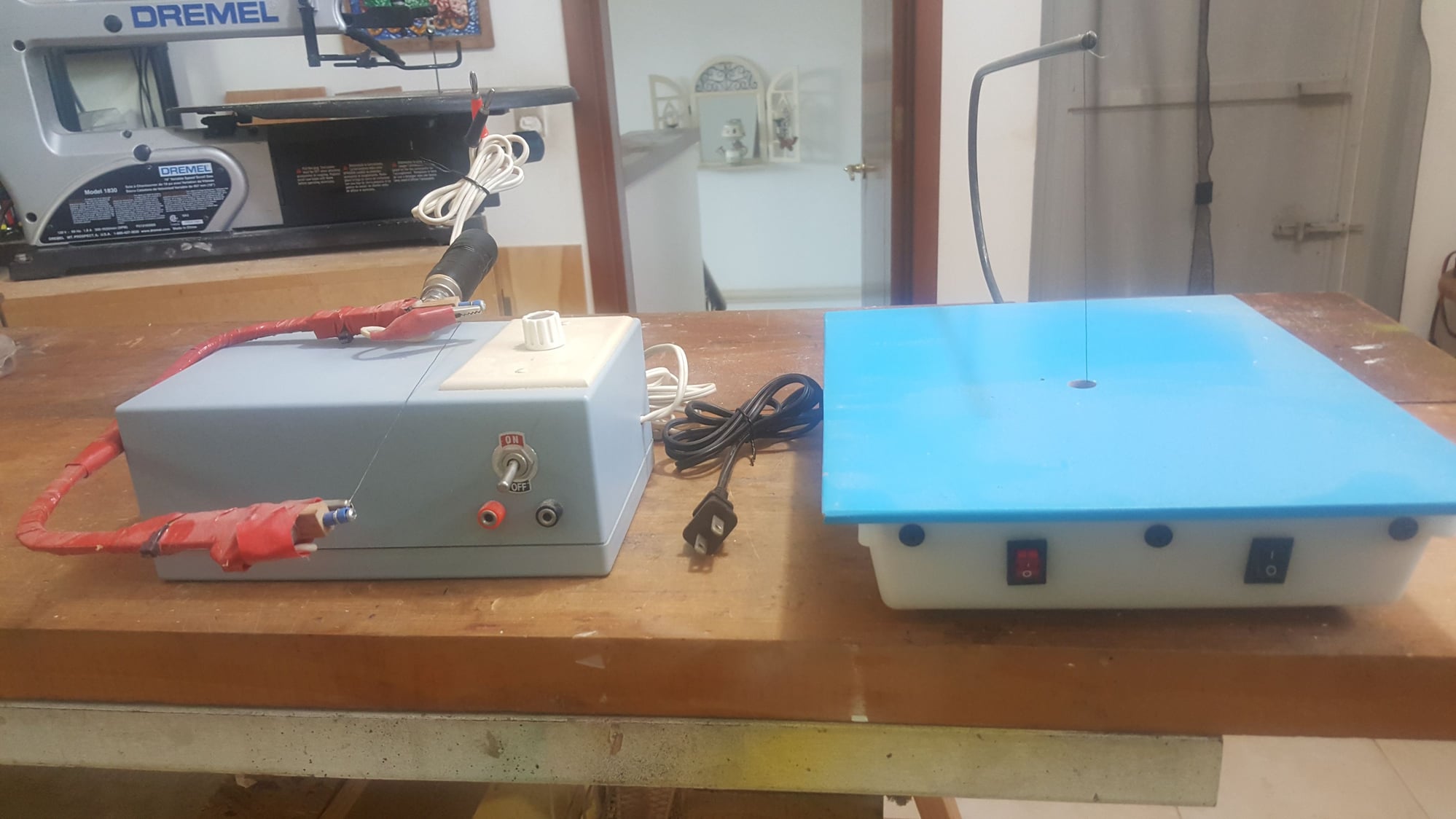
My two foam cutters.
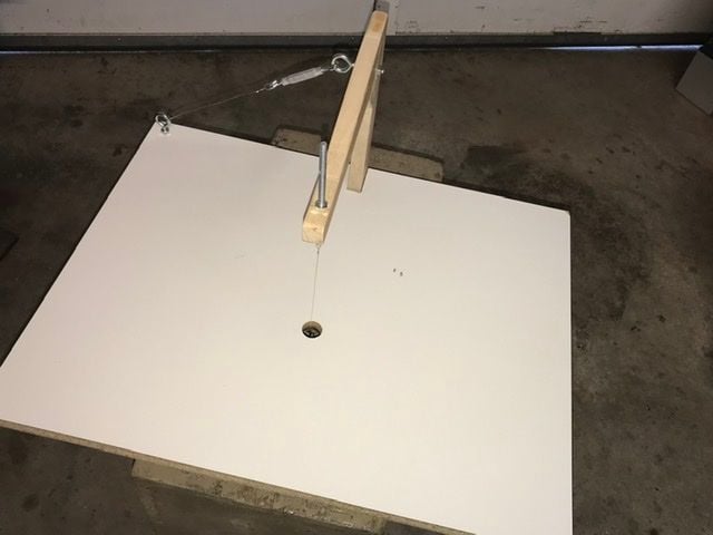
It is interesting learn new things. Maybe I'll make foam plane too. I need began construction of my jig to cut foam for wings. I maked one for small cuts. Please, send me orientation for measurements and tecnic info.
Last edited by stearman70; 08-02-2020 at 09:57 AM. Reason: Send pictures.
08-02-2020, 01:57 PM
#42
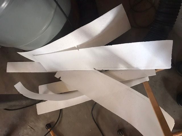
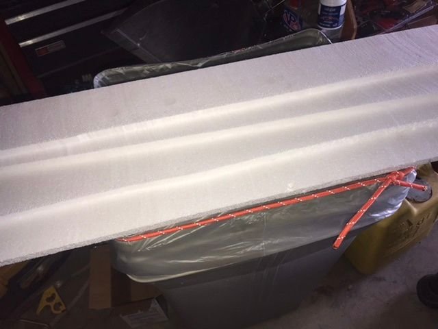
Here are some pictures of my foam work; non RC work. The bows pictured did not work too well for my airplane build. I will make new ones. The vertical cutter needs a little rework. An easier way to adjust the wire for vertical and square to table. Easy to do left to right adjust. A pain for front to back adjust. Will change this. Also found a foot switch to turn wire on and off would really help. As well as a fence for the table.
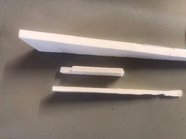
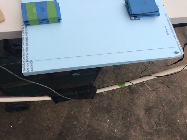
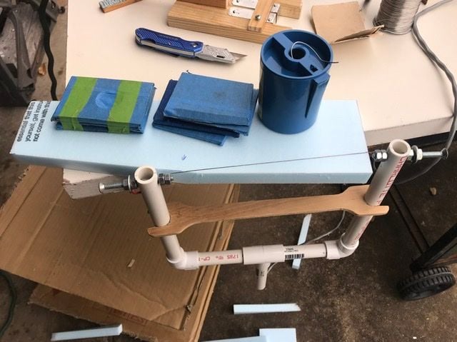
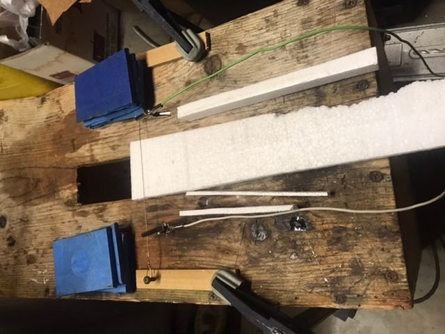
Just sample cuts of wing core and how to thin foam. The wide wire and foam picture is how I sliced the foam thin. Worked well.
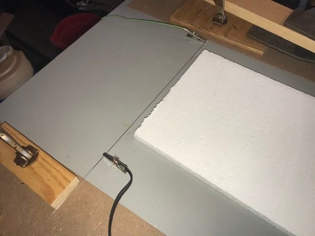
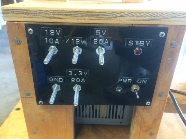
The stacked ˝” foam for the airplane. My power supply is from a computer power supply. I’ve made 2 of them. One to power the various cutting bows and the other the vertical table cutter. I adjust the wire heat by selecting different voltages and also I use a wire resistor that I made.

Just sample cuts of wing core and how to thin foam. The wide wire and foam picture is how I sliced the foam thin. Worked well.
The stacked ˝” foam for the airplane. My power supply is from a computer power supply. I’ve made 2 of them. One to power the various cutting bows and the other the vertical table cutter. I adjust the wire heat by selecting different voltages and also I use a wire resistor that I made.
08-14-2020, 05:30 PM
#43
Thread Starter
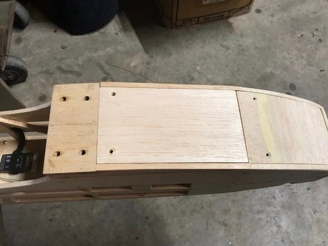
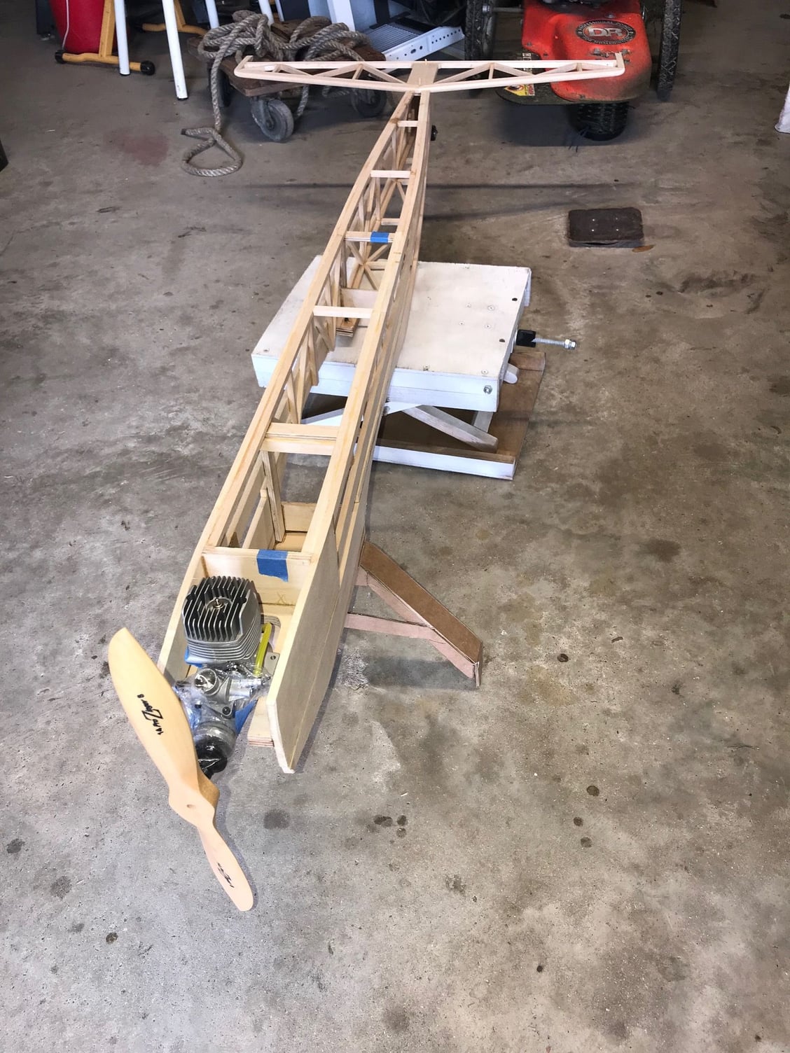
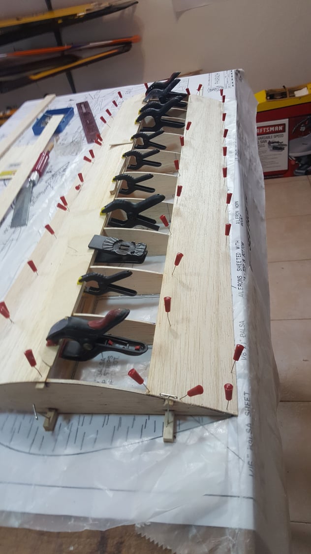
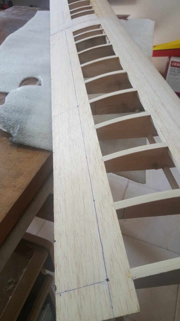
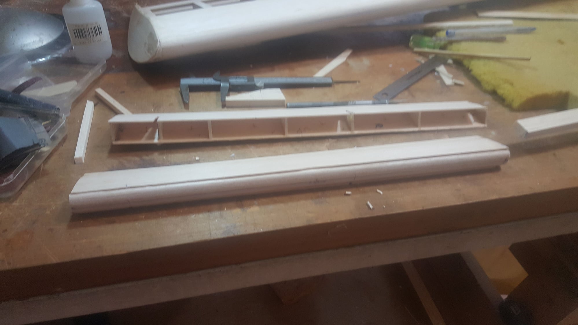
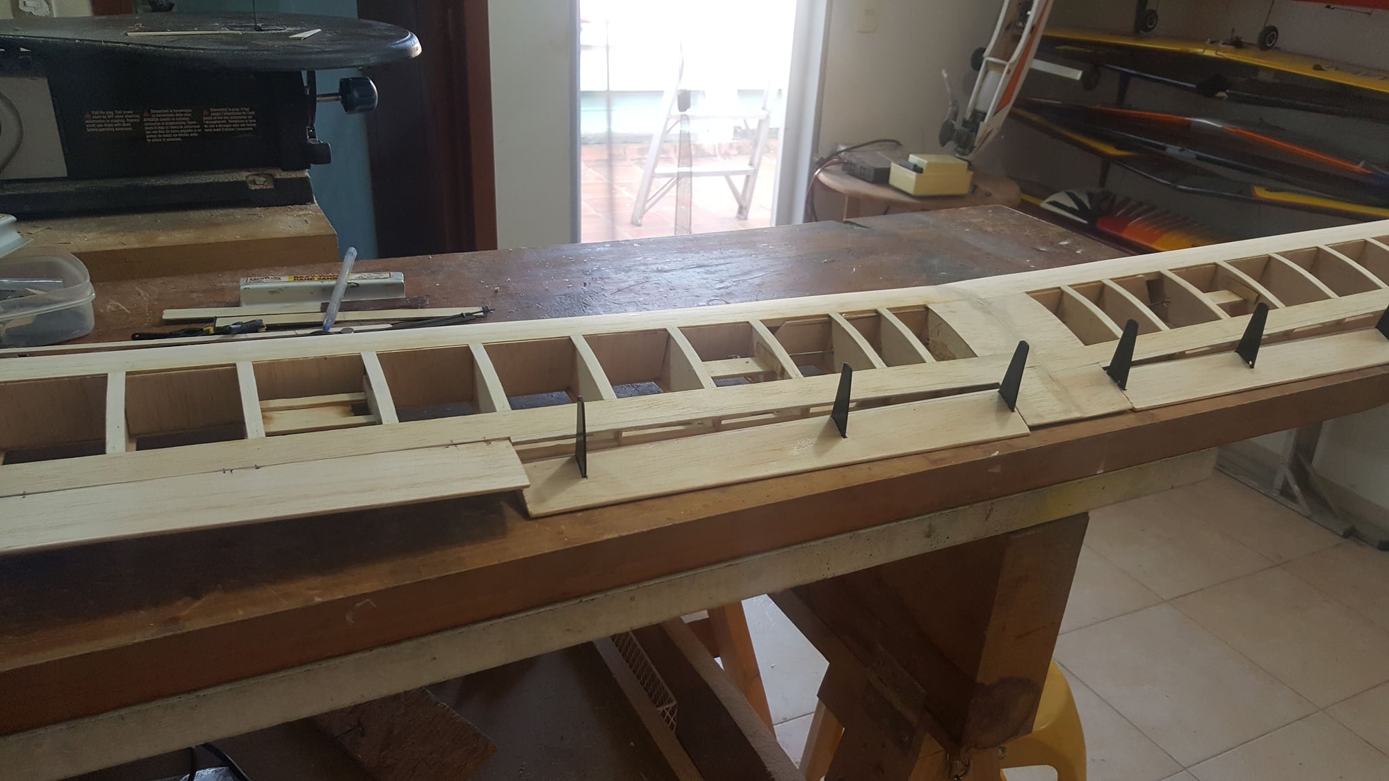
Hello. I've been fixing the plane's mistakes. The wings are advanced, but there is still a long way to go. Today I joined them and cut a flap and a wing of the same wings. I'm waiting for the aluminum parts that will be the wing supports and 1/32 aluminum for the slats. When I get those parts, I'll put them in the fuselage and keep assembling. It's going to be tricky to put the triplay supports on the wing, because I have to make an incision in the joiners, so they can get through them. When you see the blueprint, you'll find out what I'm talking about.
08-15-2020, 03:15 AM
#44
Looking good. I cut my ailerons just as you do. I have some of those red pins you are using. The head can come off if stuck good. I now use needle nose pliers to pull them out by the wire. I also use sewing pins which are thin. On those you do need the needle nose pliers.
I can’t tell from your pictures but those wing support plates should have been done earlier. Much more difficult now. If I’m understanding it correctly.
I can’t tell from your pictures but those wing support plates should have been done earlier. Much more difficult now. If I’m understanding it correctly.
08-15-2020, 09:56 AM
#45
Thread Starter
Hello. First I thought the same as you, but already on the fly, I saw that first I had to build the wing and then place the bases because we had to drill the joiners properly. It has been laborious to fix blueprint errors, but not difficult. I'll go ahead and send you pictures and comments about it.
08-18-2020, 05:56 PM
#46
Thread Starter
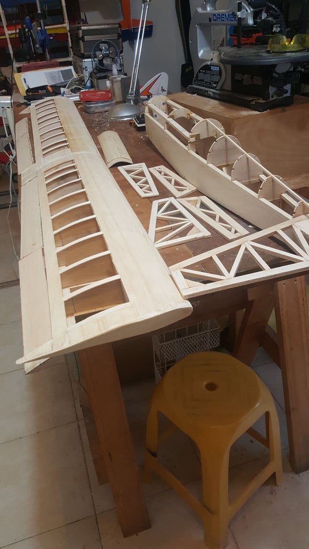
Hello. I finished the support plates. I work hard but good. My next step is to make the two bottom hatches. I still don't decide whether to put one servo in the middle of the wings for the ailerons by means of bellcrank and a slim servo on each side for each flap or vice versa. I'll began to put servos' base and push rods. Thursday I´ll receive the aluminium items for wings supports, slats, and horns.
08-19-2020, 03:34 AM
#47
It’s starting to look like an airplane. You have made good progress. Regarding servos for the wing ideally, IMO, 4 servos would be best. In a 3 servo setup, I’d go with 2 Servos for the ailerons and 1 servo via bellcranks for the flaps. You will be using the ailerons more often then the flaps. Plus the flaps via bellcranks is a shorter distance for the setup.
09-04-2020, 04:52 PM
#48
Thread Starter
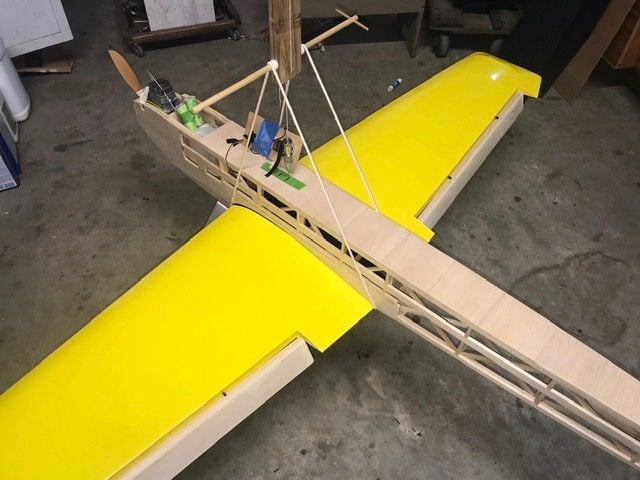
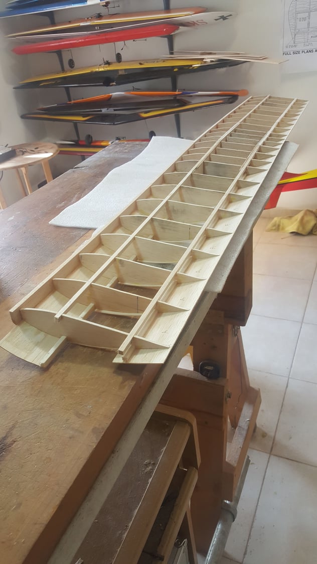
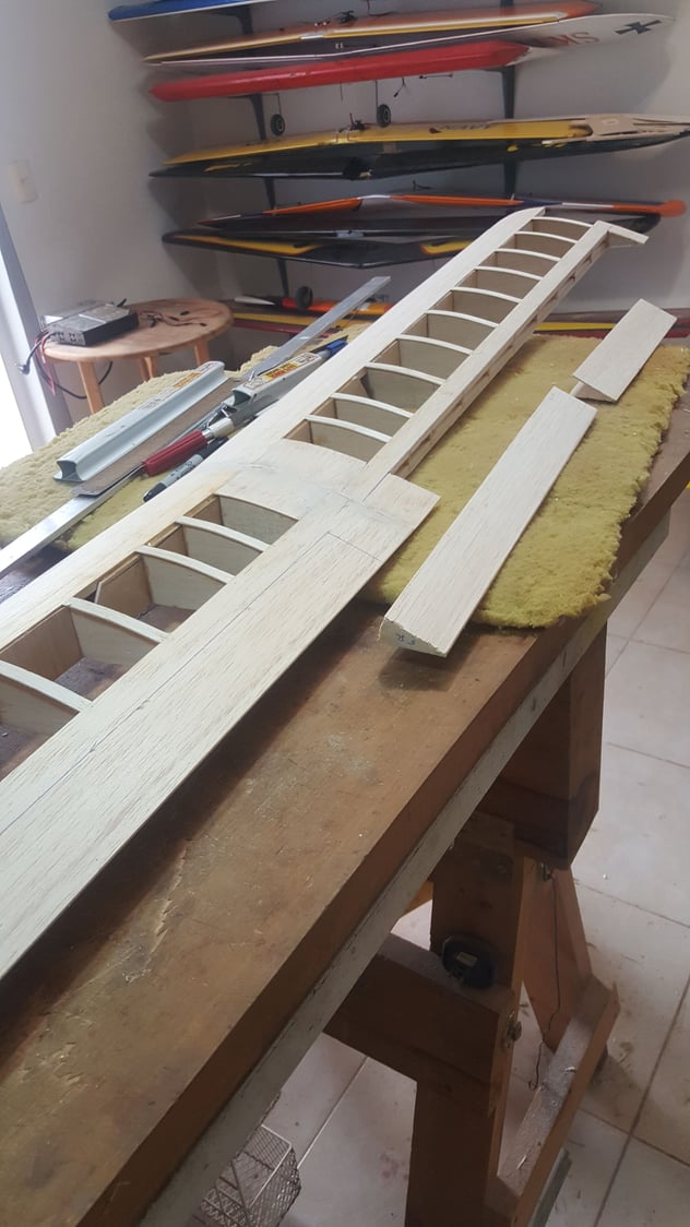
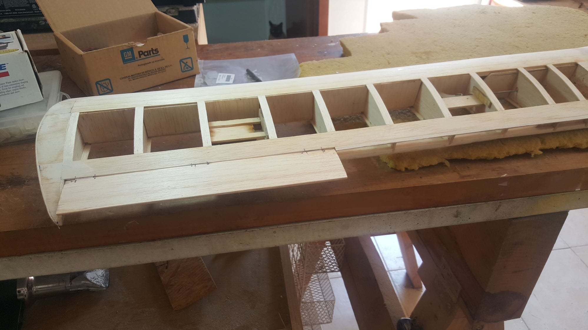
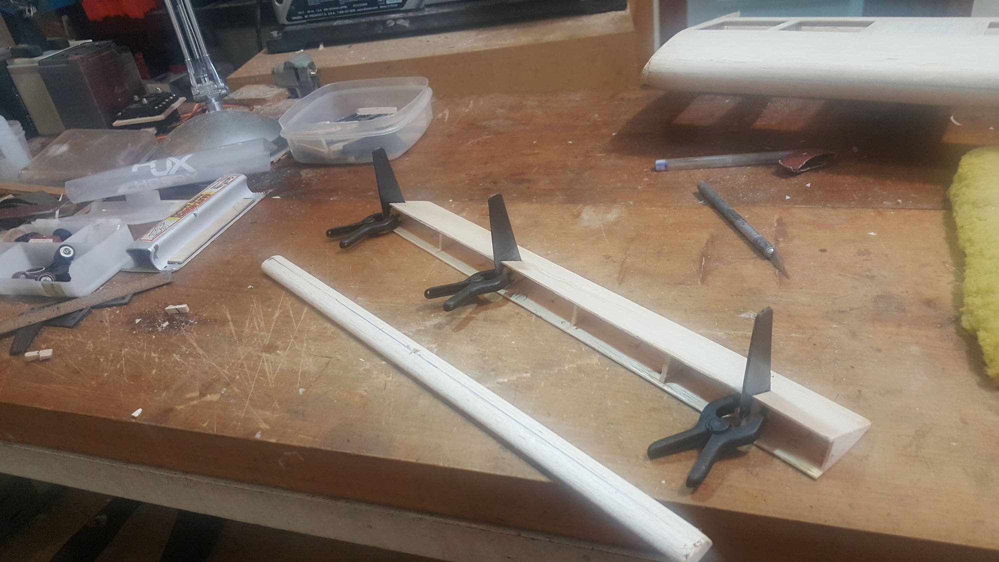
Hello. I'm here again. I'm going slowly but surely. I finished flaps and alerons. I just need the finishing touch. I've got the servo hatches ready on the wing. It has been interesting to build the flaps and their hinges according to the plane. I put three instead of two, as I mentioned at the beginning. When they're going to work, they're going to work fine. It hasn't been difficult, but it's laborious. The flaps are presented upside down, obviously they are flipped with the hinge down.
Aleron with hinges
Flap construction.

Aleron with hinges
Flap construction.
Last edited by stearman70; 09-04-2020 at 04:57 PM. Reason: Add info
09-05-2020, 03:40 AM
#49
You have progressed along nicely. Good quality build. Looking at the plan this is not an easy build. A labor of love. This airplane would be good in kit form. More complicated in a scratch build. Waiting for the next update.
I built my Foamy Profile. I have to install the electronics and do a maiden flight. Hope it flies.
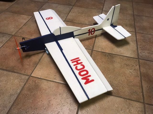
I built my Foamy Profile. I have to install the electronics and do a maiden flight. Hope it flies.