DC-3 / LI-2 / ЛИ-2 / Scale M1:5 by Hungarian modeler
 06-30-2022, 08:53 AM
#26
Ok Jozsef. I hope the builder will have more time to spare to build this nice aircraft. Would love to see more photos of the construction when you have them available! Do you think you will be making kits for sale if everything goes well with the flying?
Thanks
Reuben
Thanks
Reuben
 07-03-2022, 01:14 AM
#27

Thread Starter
Reuben -
I will show you pictures of this model when I have them.I have not thought about the kit because I use SOLID EDGE academic license and need permission to use this CAD program for business from the Hungarian graphIT Ltd.
https://graphit.hu/
I saw how big this model is, the pictures do not give back the size, and I have seen my friend how much time worked on it so far.
I respect him for this work.
I think this size, DC-3 / LI-2 scale M1:4 not interesting for the modeler.
10-18-2022, 09:39 AM
#29
Thread Starter
I have finished drawing the rudder.
Do you have any suggestions?
.https://drive.google.com/drive/folde...6G?usp=sharing
.
.
.
Do you have any suggestions?
.https://drive.google.com/drive/folde...6G?usp=sharing
.
.
.
10-18-2022, 10:52 PM
#30
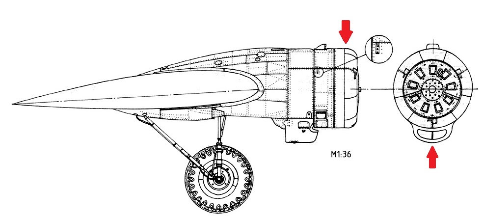
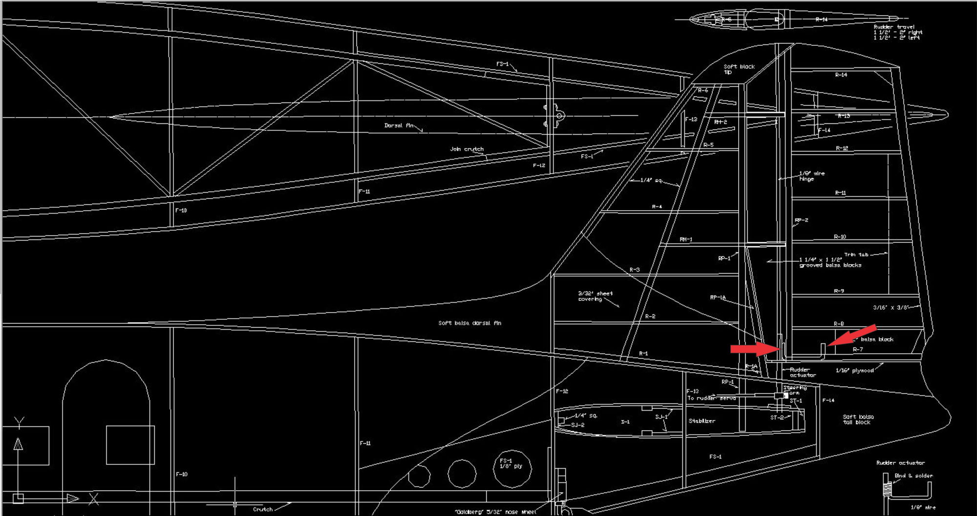
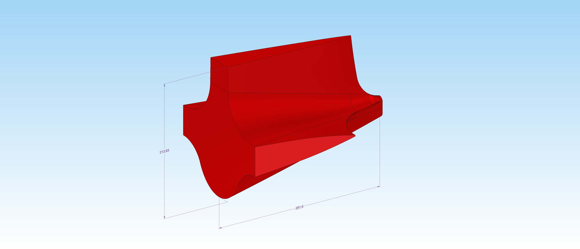
Hi Jozsef. Interesting setup. In my opinion, one could make a steering arm and two carbon fiber tubes to control rudder. The tube on which the rudder turns I would make it square and not round. Better still is to make an extension to the rudder shaft (see photo marked in red) so you will have a stronger turning force rather than relying on the thickness of the shaft alone. I prefer if the rudder shaft is made square instead of round and then attach an extension to it as per enclosed drawing. I understand that the DC-3 has a long tail moment and one needs to put enough weight in front of the CG. In the case of the Ziroli DC-3 they usually use two Zenoah G-38 for power as whilst they are reliable they are a bit heavier than other engines. I think that the rudder shaft has to be made of metal so now you have to evaluate whether it is worthwhile going this route of using a metal rudder shaft (weight wise) or placing a servo closer to the pivot point of the rudder. This will avoid all the long connections or carbon tube needed to control the rudder surface, See what's best for you. I know that you have always got to keep in mind the backside weight of the aircraft as I am sure you will be needing front weight to obtain the correct CG (Centre of Gravity) position.
Hope this helps.
Reuben
Hope this helps.
Reuben
10-21-2022, 11:11 AM
#31
Thread Starter
Hi Reuben,
Thanks for the good advice.
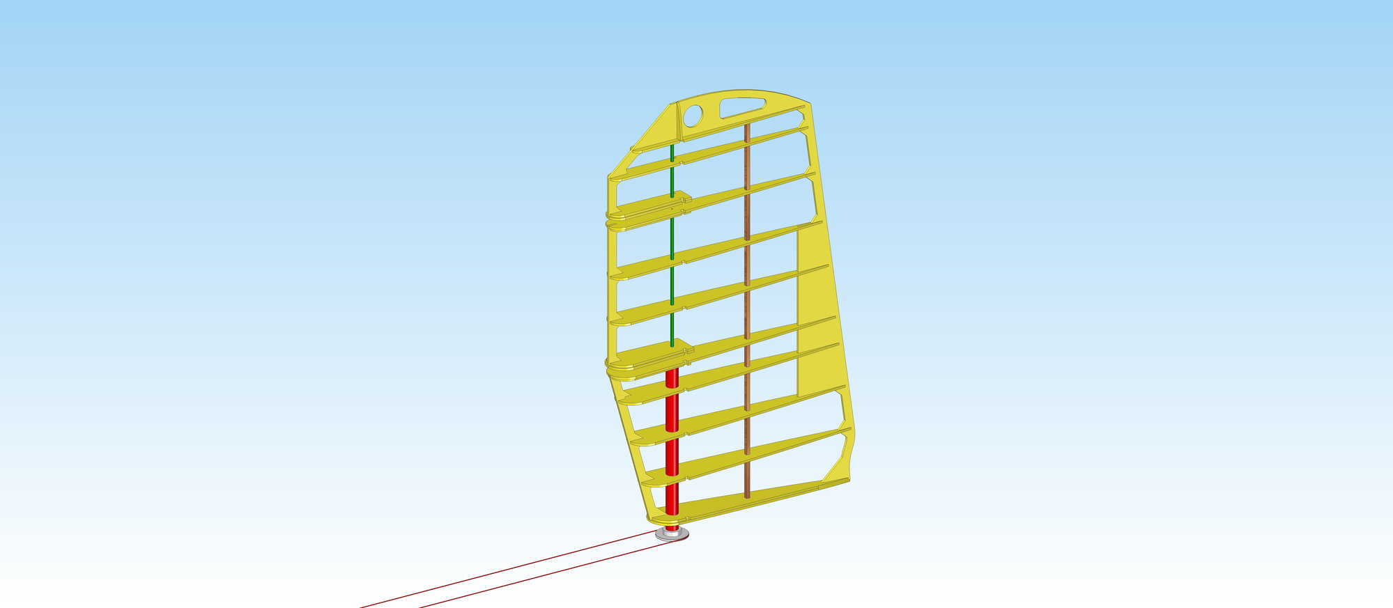
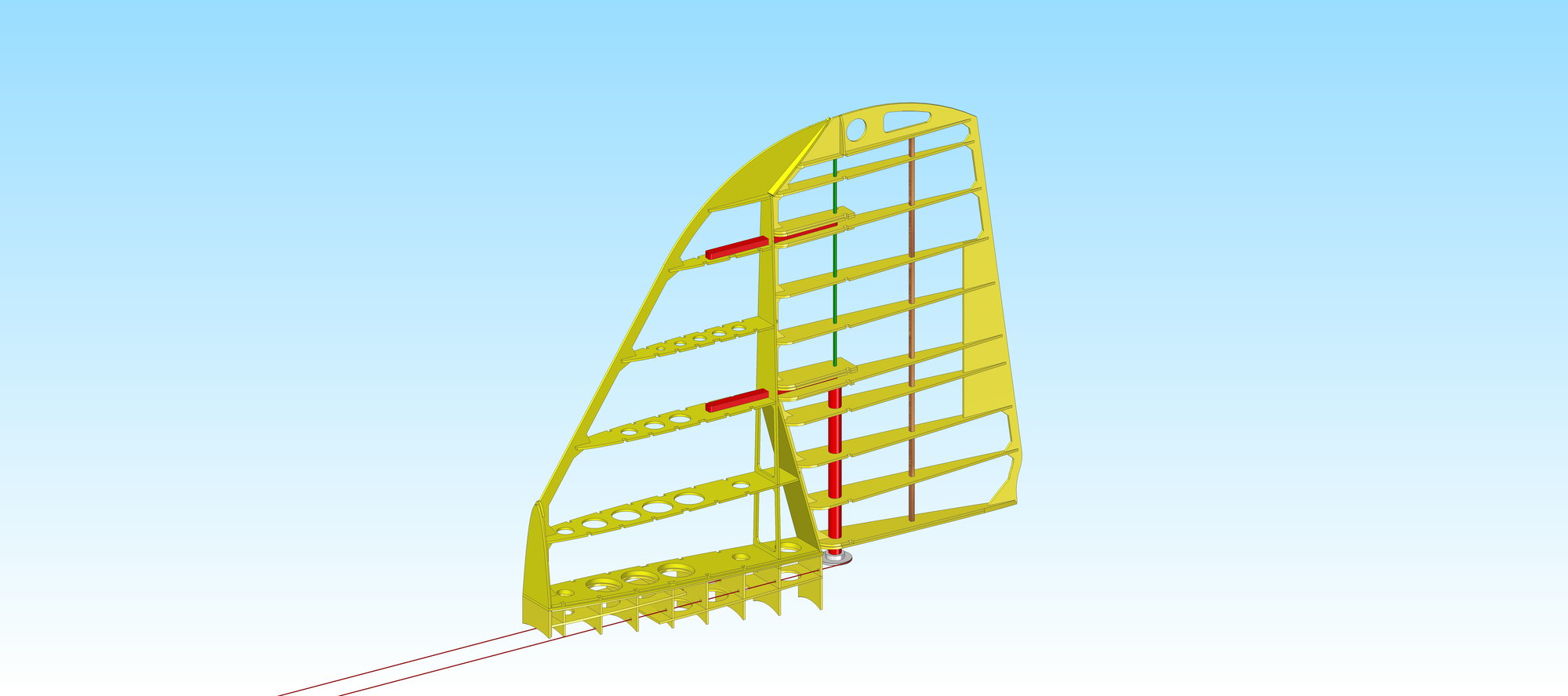
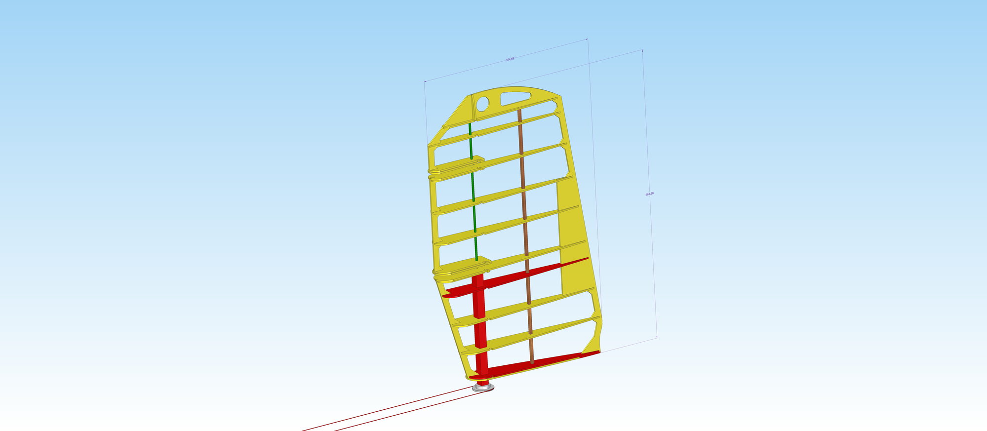
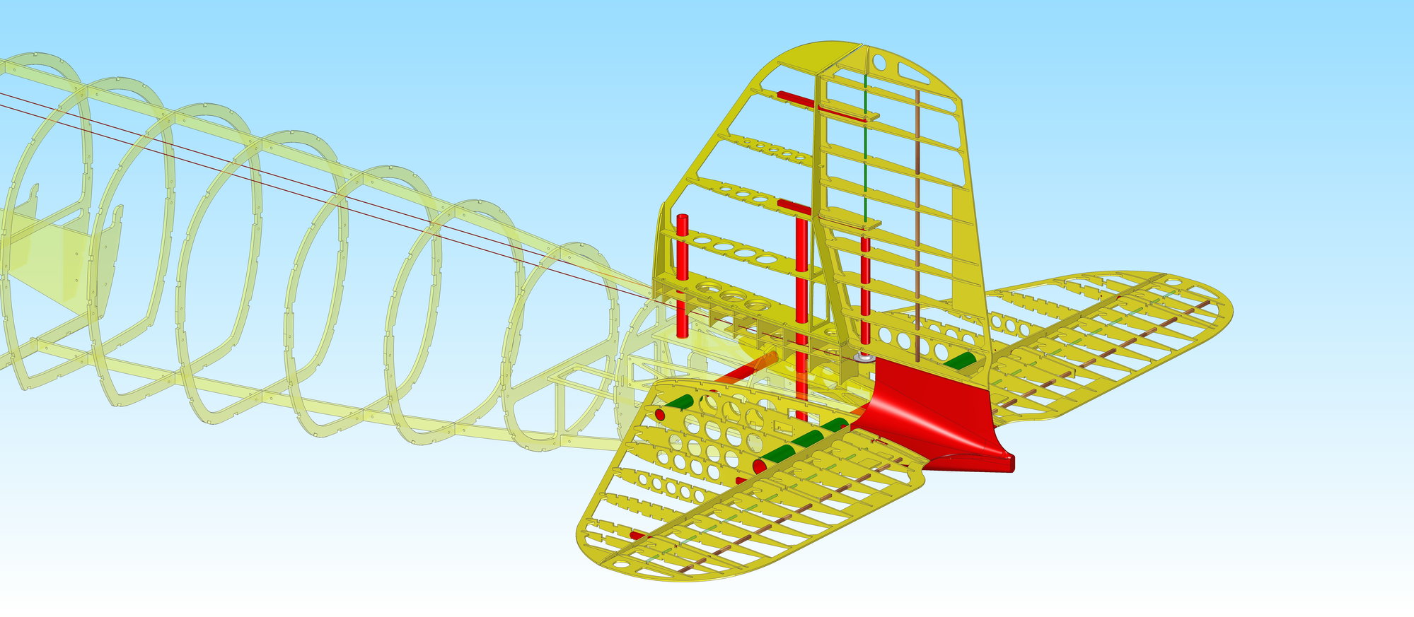
I studied Ziroli�s DC-3 plan. I don't know if this solution for moving the rudder would be strong enough for this size. Look at the measurements (mm) in the picture!
The picture shows my plan.
The yellow ribs are made of 3mm plywood and the red ribs are made of 3mm carbon plate.
The lower red shaft is a 16x16mm 1mm wall thickness carbon tube.
The builder, my friend, asked me to draw a circular cross-section of the shaft. He is still thinking about the rudder construction.
J�zsef
.
.
Thanks for the good advice.
I studied Ziroli�s DC-3 plan. I don't know if this solution for moving the rudder would be strong enough for this size. Look at the measurements (mm) in the picture!
The picture shows my plan.
The yellow ribs are made of 3mm plywood and the red ribs are made of 3mm carbon plate.
The lower red shaft is a 16x16mm 1mm wall thickness carbon tube.
The builder, my friend, asked me to draw a circular cross-section of the shaft. He is still thinking about the rudder construction.
J�zsef
.
.
10-22-2022, 08:29 AM
#32
Hi Jozsef,
I see you made some alterations to the rudder. Good that you added the carbon ribs. I like the idea as it makes sense! Well of course you can move the rudder with cables. Not a problem! I would also check the weight difference of putting a servo closer to the moving surface as opposed of running cables etc. Don't forget that you will have the weight of the cable and rotating arm (probably made of aluminium?). Having the servo closer to the moving surface will make it more effective and slop-free. Yes there could be a weight penalty if the servo is heavier which in the end will be reflected by more weight in the front in order to obtain correct CG balance. You have to calculate it to see which is the best for you.
Regards
Reuben
10-23-2022, 10:30 AM
#33
Thread Starter
 11-22-2022, 10:02 AM
#35
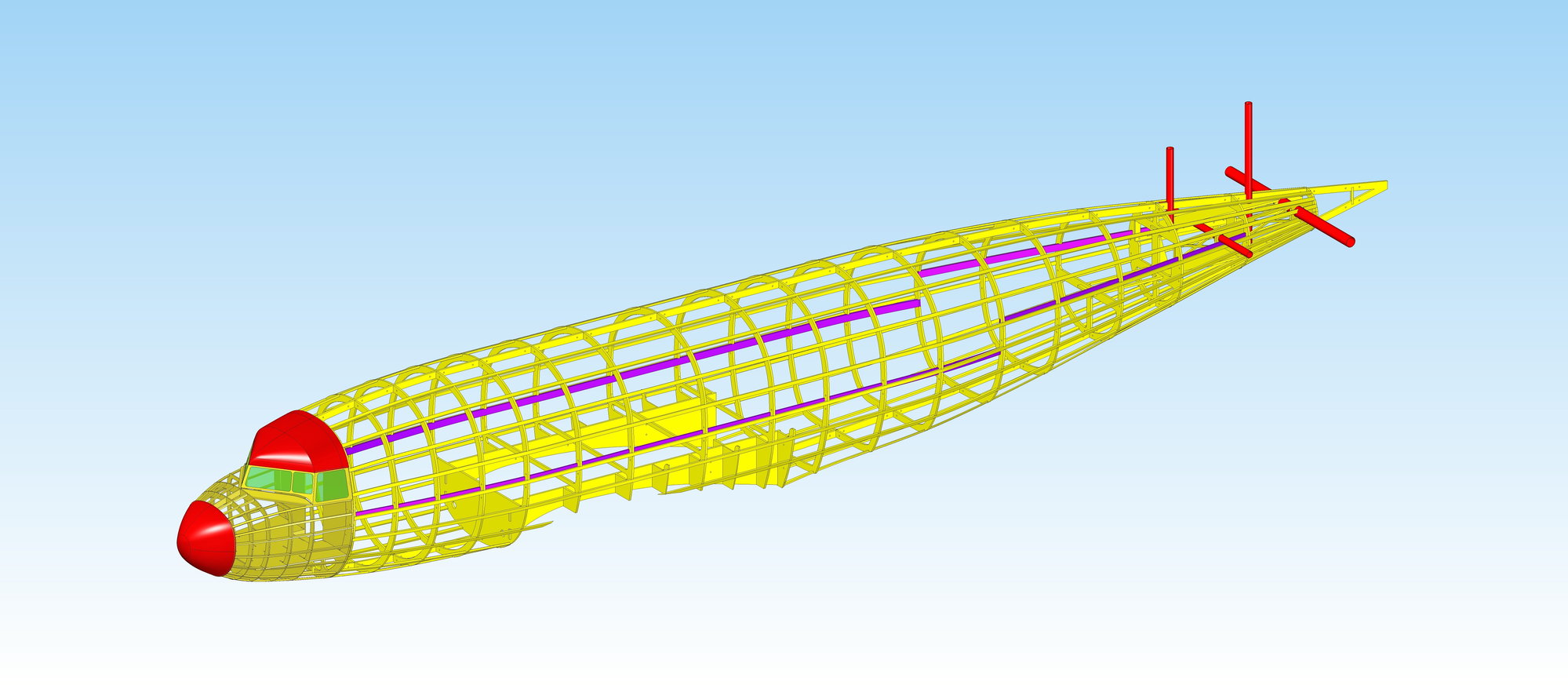
Hi Jozsef. I suppose that the wing will have to be divided into three sections, the center section and the two outward wing panels.. The center section will have to include the engines, flap and, if the center section is big enough, the retracts, retracts mechanism and air bottles (if air is going to be used). This will avoid the need to use festo (if the bottles will be held inside the fuselage) to separate linkages between the air bottles and the retract mechanism. Wing ribs in the outward wing panels will have to include washout in the wings so that one gets the proper washout angle when the wing ribs are made. Presumably the wing saddles will have to be made separately but the fuselage formers should have the framework ready to eventually glue the wing saddles with the fuselage framework. Your above drawing does not include the wing saddle extensions so most probably the center section fuselage formers will have to be modified to include this feature. The saddles will have to be supported by the extension of the fuselage formers from both the top and bottom without leaving too big gaps between them and the wings. Of course it will be helpful if the plans would also include the location of the servos and the attachment points of the center section and the fuselage. Just my thoughts
Reuben
Reuben
11-30-2022, 09:59 AM
#36
Thread Starter
Reuben - Thanks.
Anyone else?
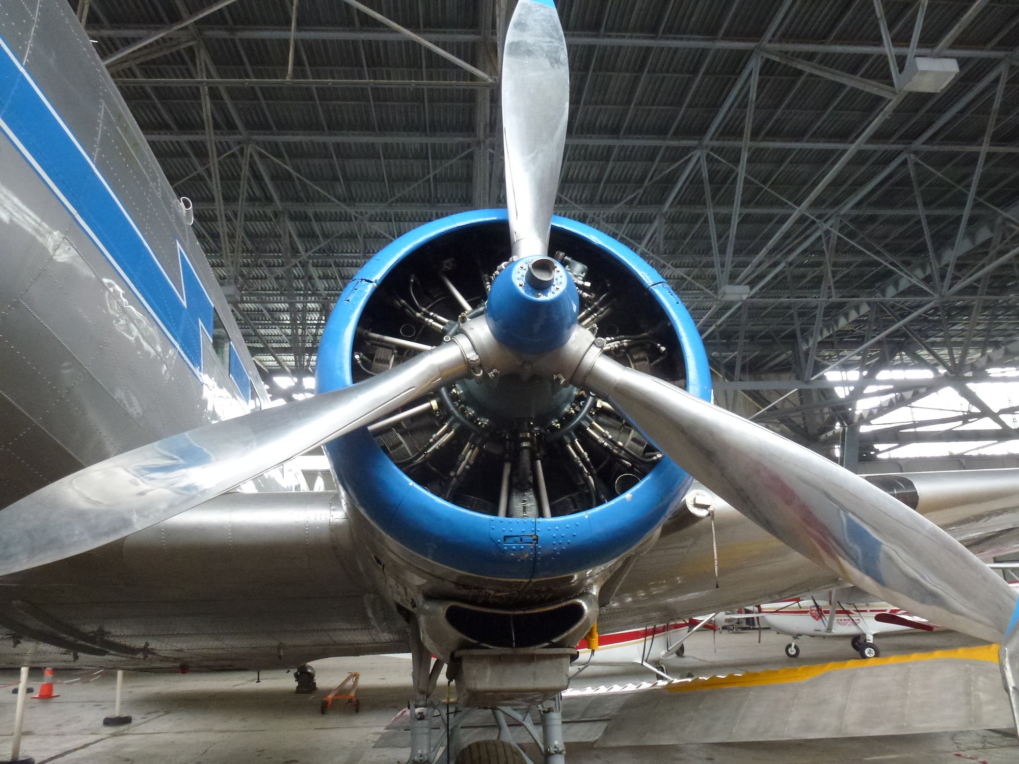
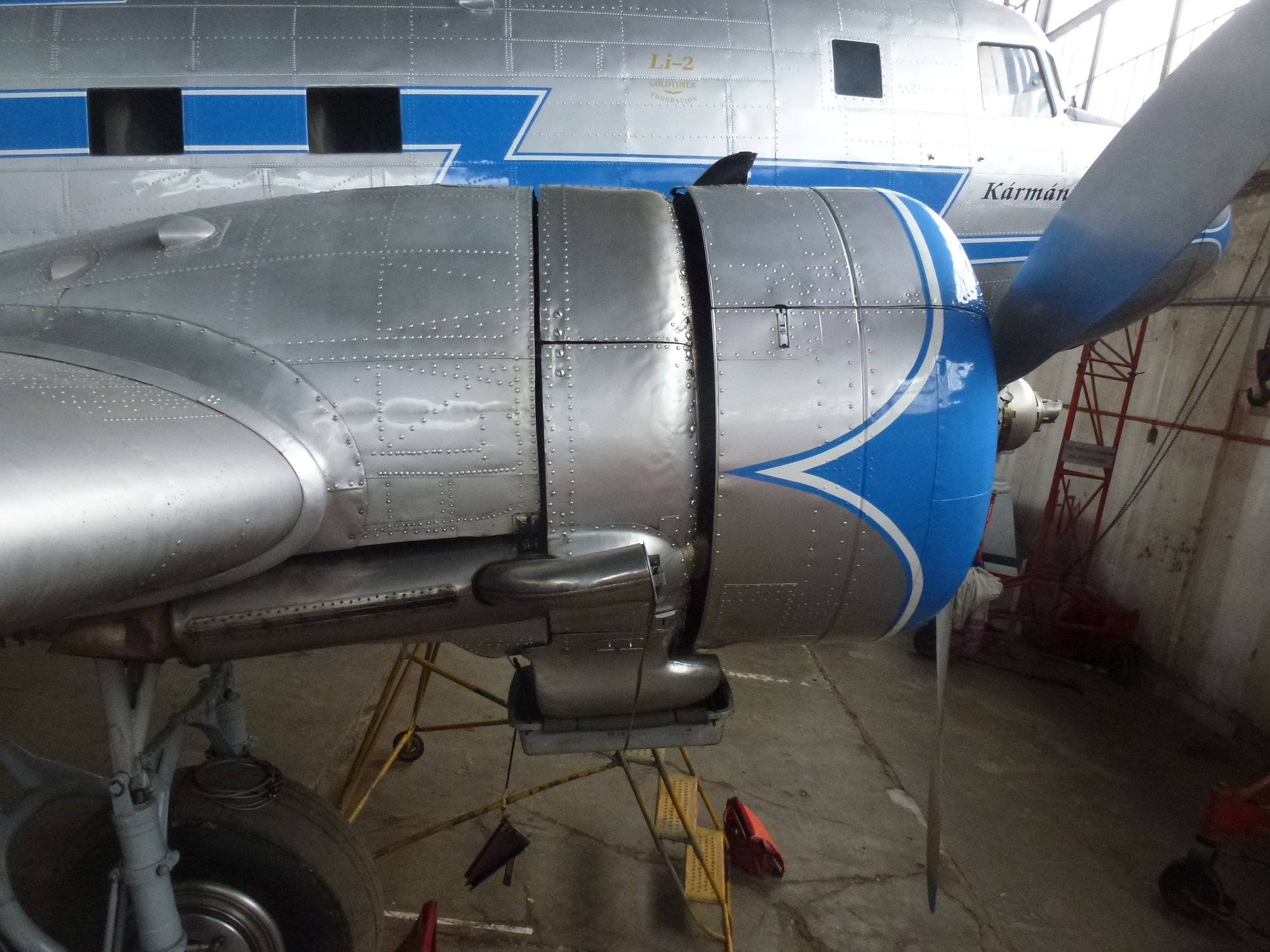
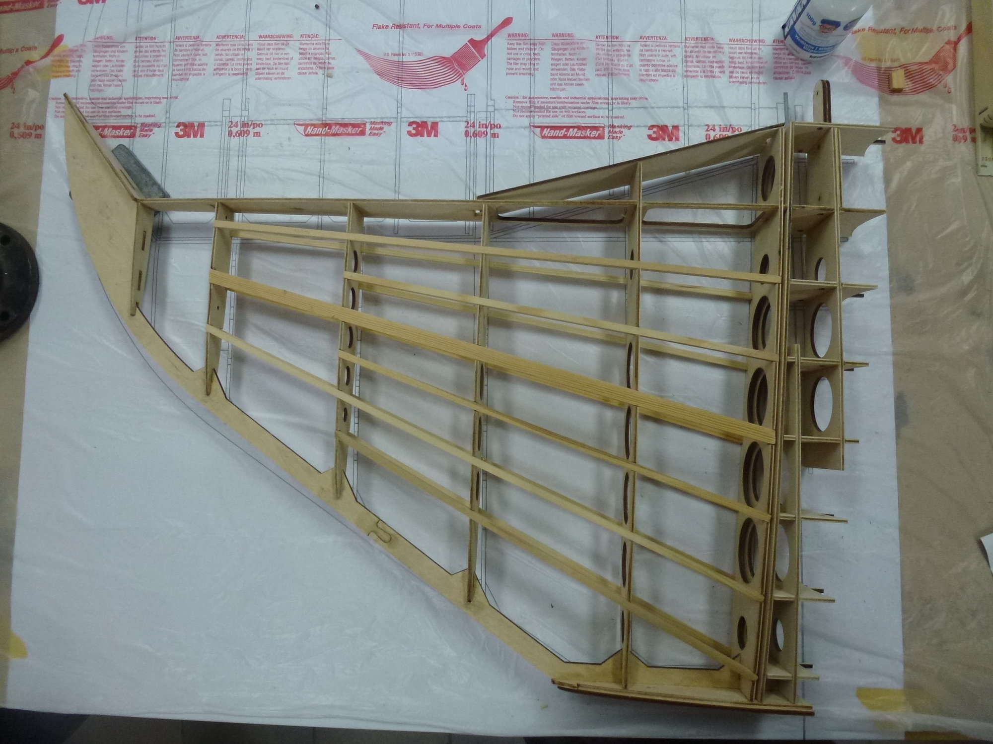
This weekend I was at the Buda�rs airfield and saw the wing of the LI-2 with the eyes of a modeler and took some photos.
.
.
Anyone else?
This weekend I was at the Buda�rs airfield and saw the wing of the LI-2 with the eyes of a modeler and took some photos.
.
.
The following users liked this post:
combatpigg (01-19-2023)
12-10-2022, 10:57 AM
#37
Thread Starter
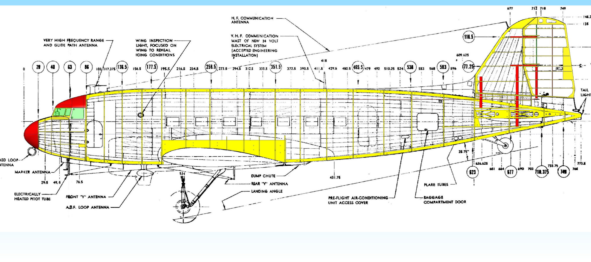
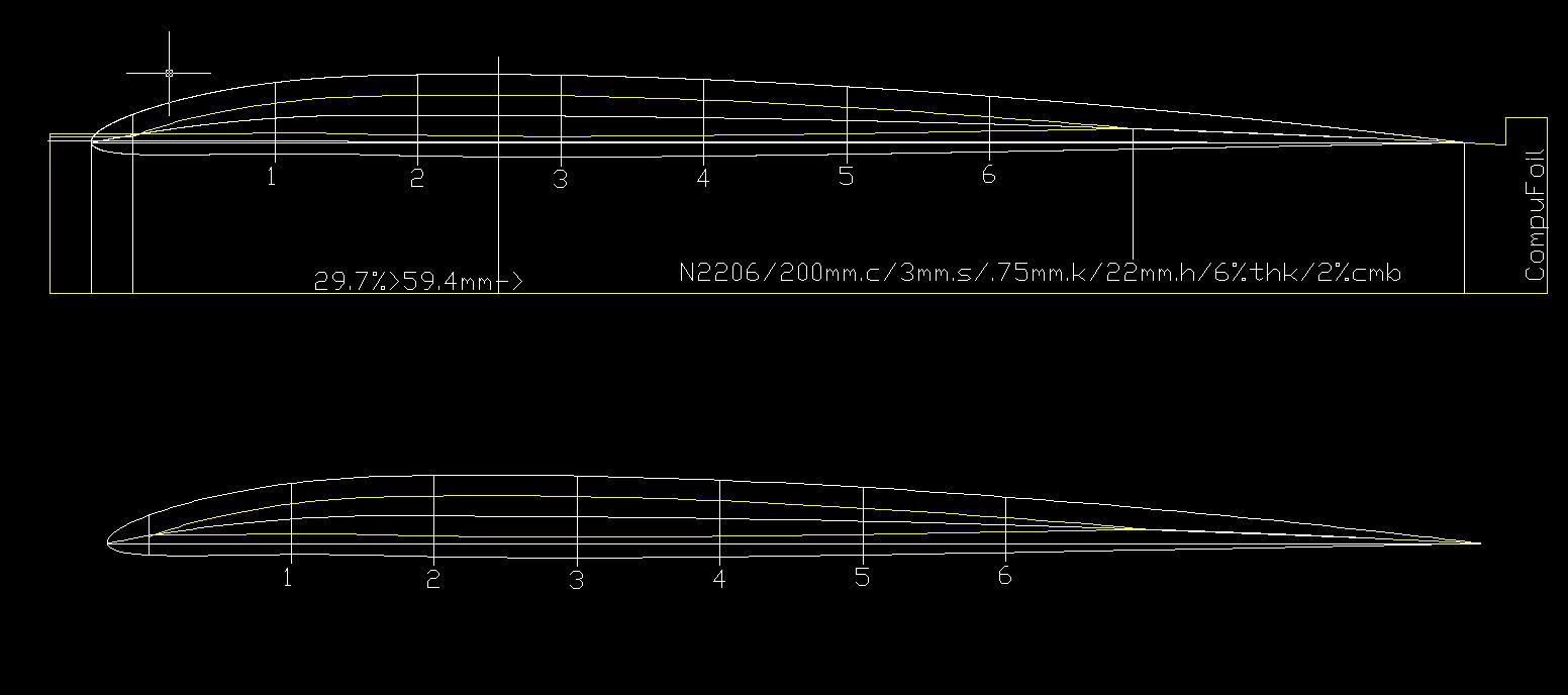
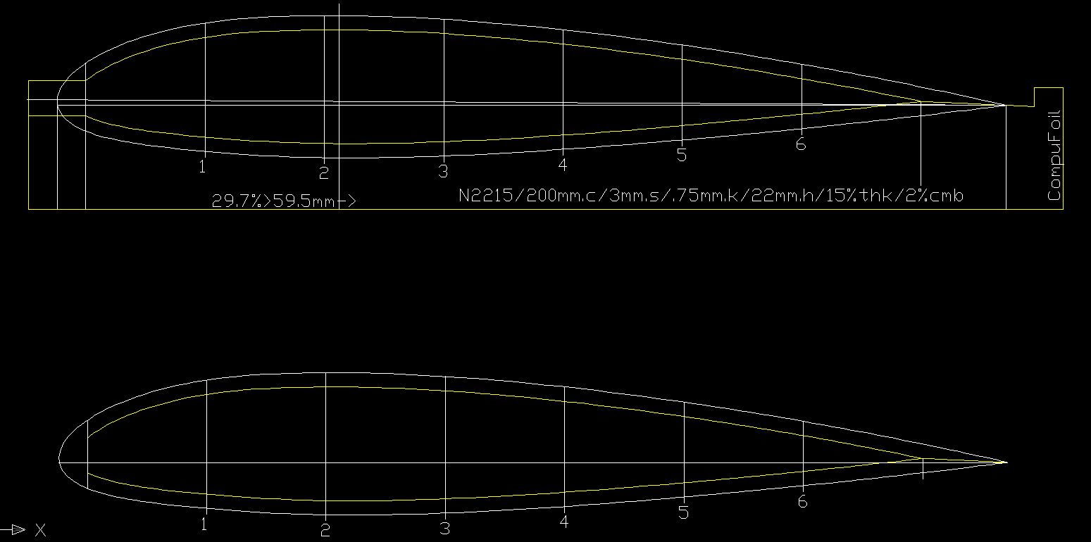
Could anybody send me NACA 2215-2206 dxf. or par. / dft. (200mm) files?
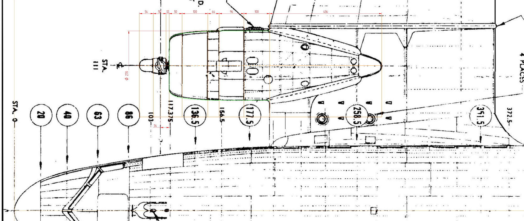
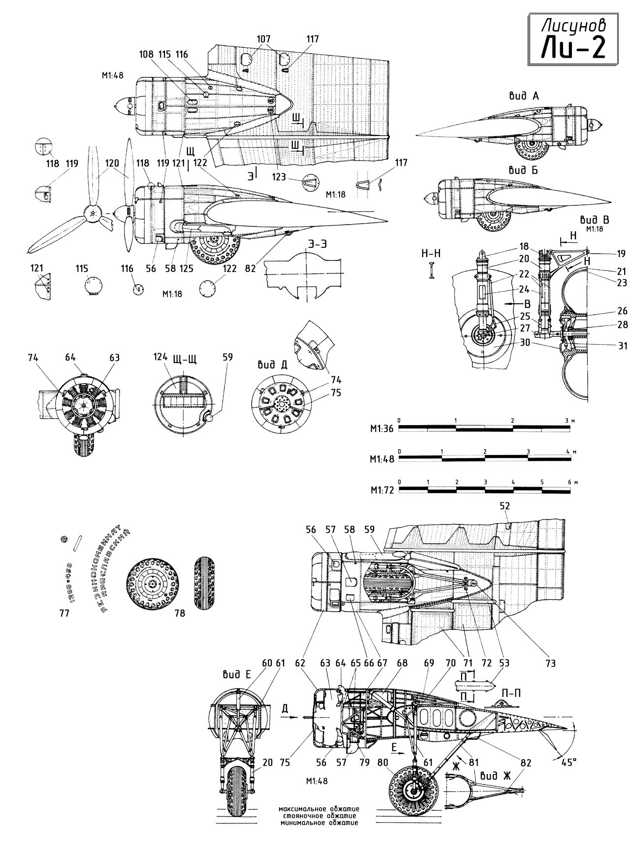
The picture is from the e-book "Самолёт ЛИ-2" (1946 г.), which I received from a good friend.
.
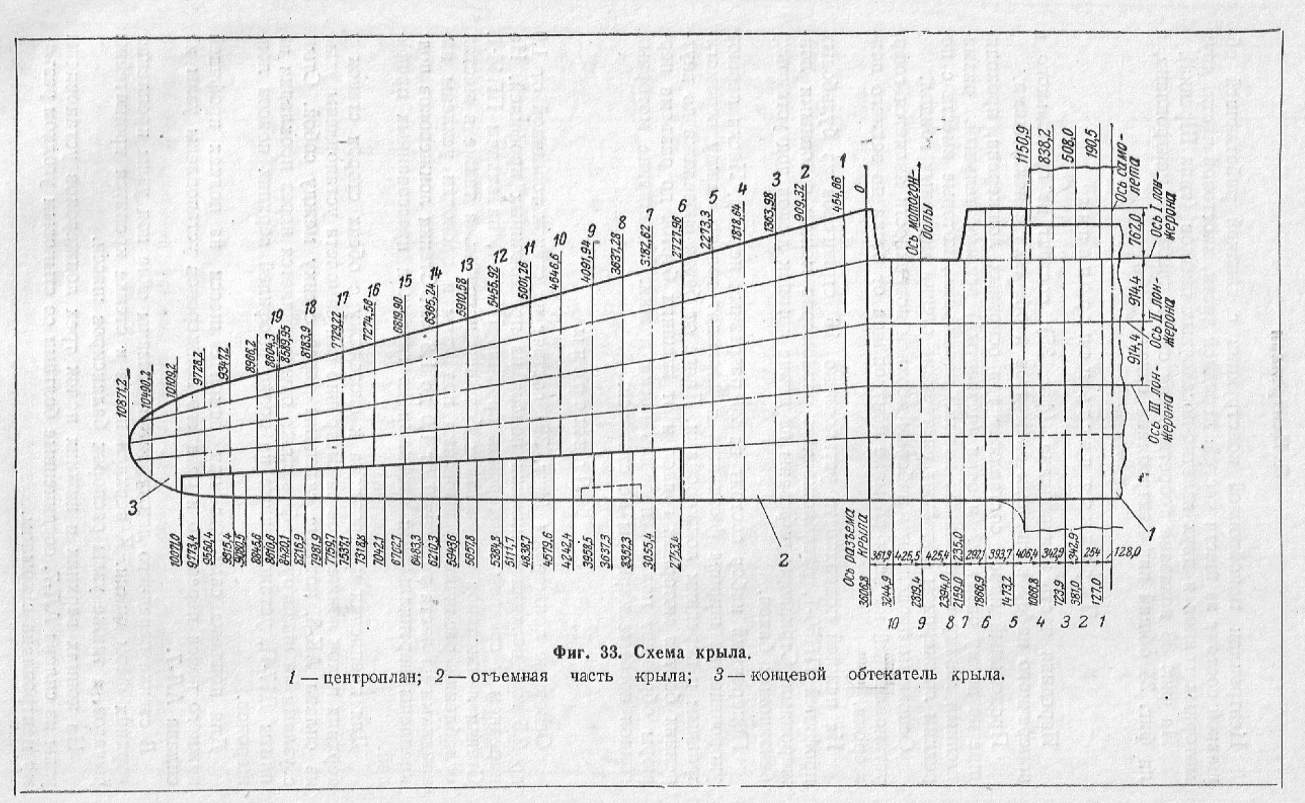
The picture is from the e-book "Самолёт ЛИ-2" (1946 г.), which I received from a good friend.
.
 12-11-2022, 02:47 AM
#39
Please note that the airfoils have a 3mm balsa covering included in the drawing. BTW one drawing is for foam cutting and the other is the traditional wing rib section.
Reuben
Reuben
 01-19-2023, 12:13 PM
#43
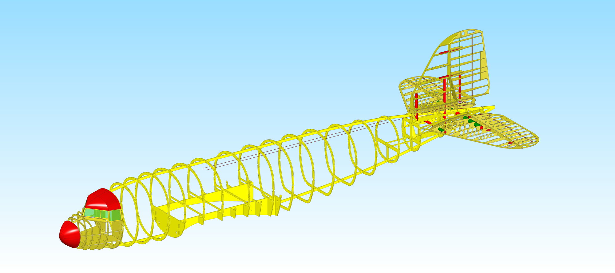
That wooden skeleton is too pretty to cover up..!
Being able to build an accurate wooden frame was the sheetmetal workers first task.
I think this project would make some sheet metal workers drool.......
Being able to build an accurate wooden frame was the sheetmetal workers first task.
I think this project would make some sheet metal workers drool.......
Last edited by combatpigg; 01-19-2023 at 12:21 PM.
01-24-2023, 02:16 AM
#44
Thread Starter
The nose cone is made from a carbon fiberglass end epoxy gel.
I also like the construction of the model.
The model construction looks good in the picture, but it is even more beautiful when I can see it at my friend's place when I visit.
I also like the construction of the model.
The model construction looks good in the picture, but it is even more beautiful when I can see it at my friend's place when I visit.
 04-26-2023, 12:19 AM
#48
Thread Starter
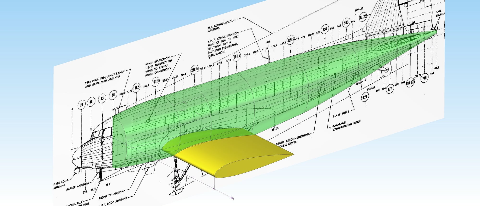
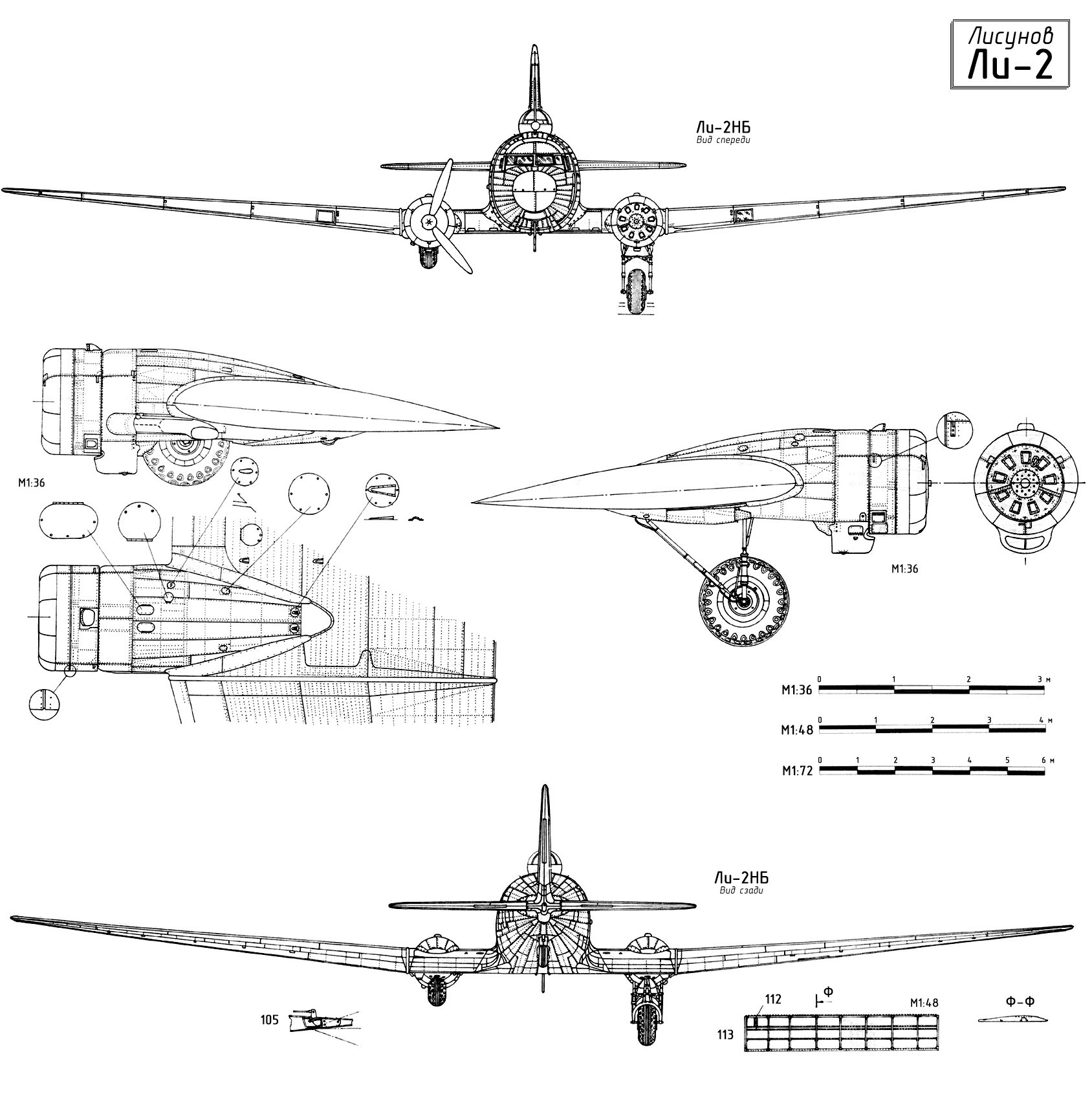
We decided that I would draw the middle part of the wing and the engine nicalle according to LI-2.
I found a good drawing here:
www.airwar.ru/other/draw/li2aiv.html
.
.
I found a good drawing here:
www.airwar.ru/other/draw/li2aiv.html
.
.