


Hobbistar 60 - Bolt-on wing conversion
 12-22-2013 | 08:43 AM
#26

My Feedback: (1)
Joined: Mar 2005
Posts: 503
Likes: 0
Received 0 Likes
on
0 Posts
From: Jacksonville, FL
While I was thinking about where to put my forward wing bolts, I checked the length of the bolt against the thickness of the wing at my first chosen position.
Nope, that's not going to work! I didn't find any 1/4"-20 nylon bolts longer than 2-1/2". Ergo, the location of the forward bolts has to change... so I put the dowels back in the fuselage, banded the wing on and marked holes in my new location.
Nope, that's not going to work! I didn't find any 1/4"-20 nylon bolts longer than 2-1/2". Ergo, the location of the forward bolts has to change... so I put the dowels back in the fuselage, banded the wing on and marked holes in my new location.
Looking as hpw you are doing yours, I don't see the load applied to the spar. Maybe I am just missing it.
Terry
 12-23-2013 | 04:57 AM
#27

Thread Starter
Senior Member
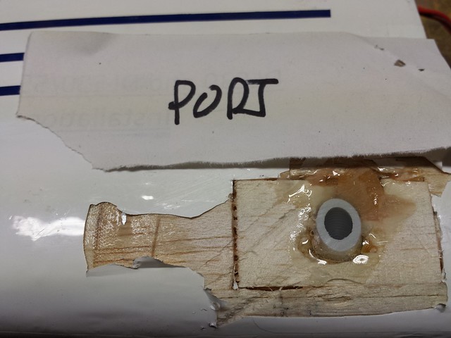
If you look at how I did mine, the wood has been counterbored so the screws can work at the standard length. The blocks are glued with Hysol to the main spar in the wing top and bottom. The wood I used was hard maple. The maple goes all they way through the wing. I cut through the covering and sheeting with a #11 exacto and found the spar then opened up the hole to have a tight fit with the maple blocks. I cut the blocks to size before gluing, tracing the wing profile into the block and shaping with a dremel after crosscutting. Then drill and counterbore holes(9/32 and 7/16 drill bits). Then locate the mating blocks in the fuse, glue (again with Hysol), and "line" drill and tap from the holes in the wing. I later added the screws to the blocks in the fuse, just in case.
Looking as hpw you are doing yours, I don't see the load applied to the spar. Maybe I am just missing it.
Terry
Looking as hpw you are doing yours, I don't see the load applied to the spar. Maybe I am just missing it.
Terry
 12-23-2013 | 05:07 AM
#29
Thread Starter
Senior Member
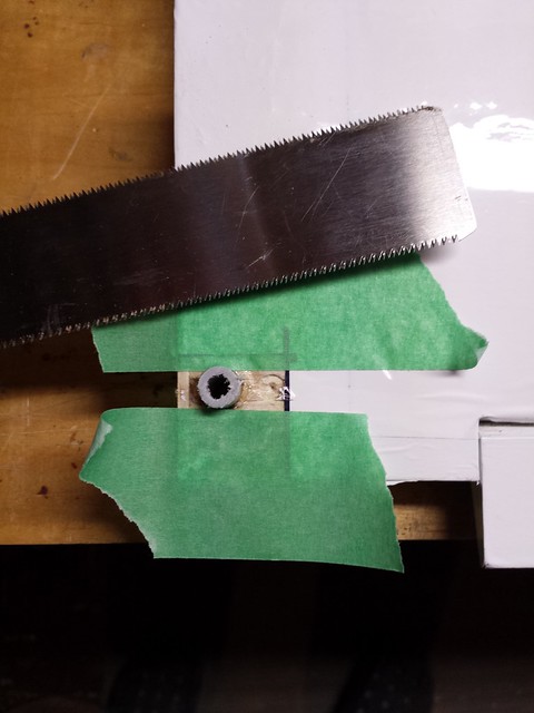
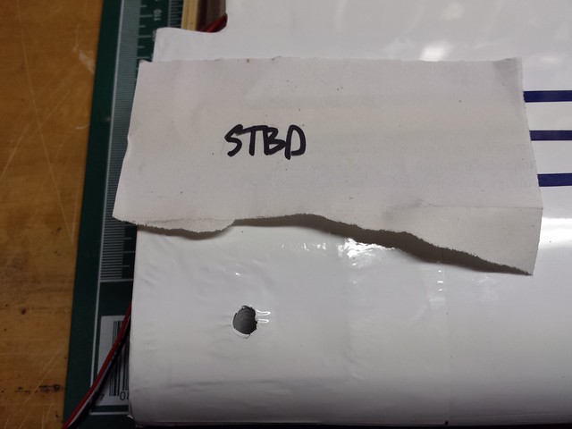
I needed to gauge the angle of the sleeve to determine the new position of the forward mount - a transfer punch through the sleeve made a handy visual reference.
The angle, transferred to the fuse.

New holes drilled.
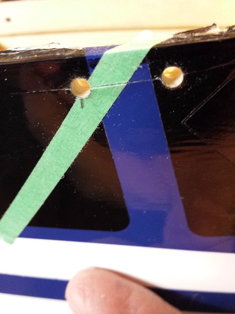
Forward mount in new position.
The angle, transferred to the fuse.
New holes drilled.
Forward mount in new position.
12-23-2013 | 05:10 AM
#30
Thread Starter
Senior Member
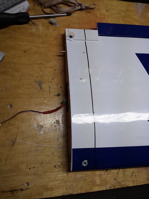
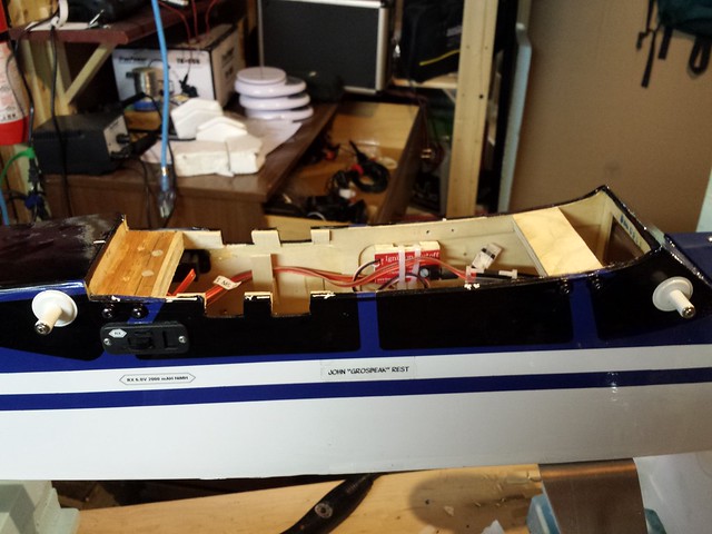
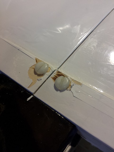
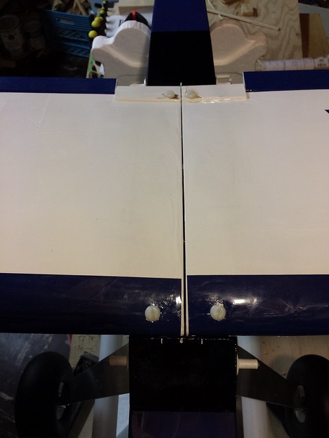
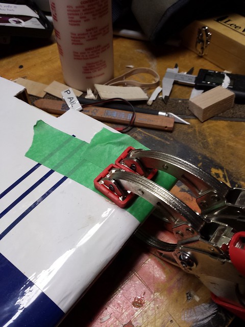
Wing bound to fuse.

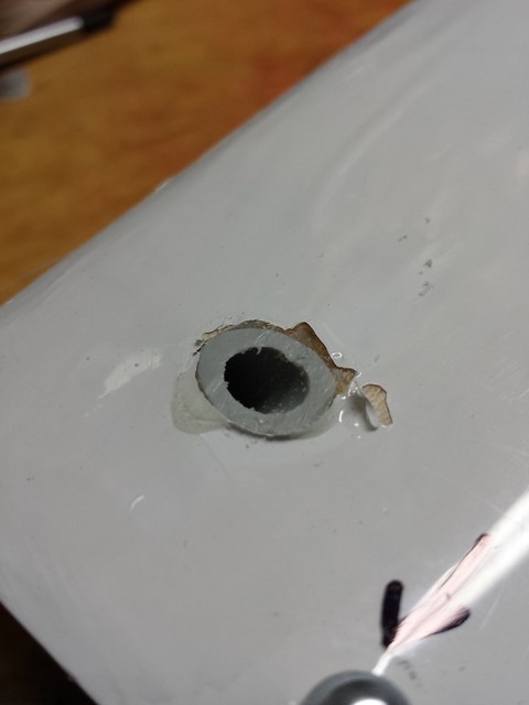
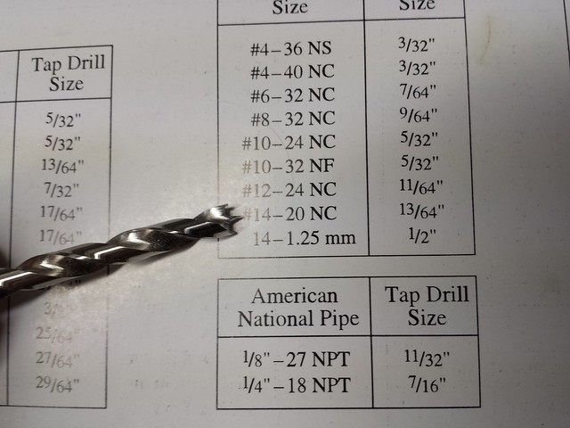
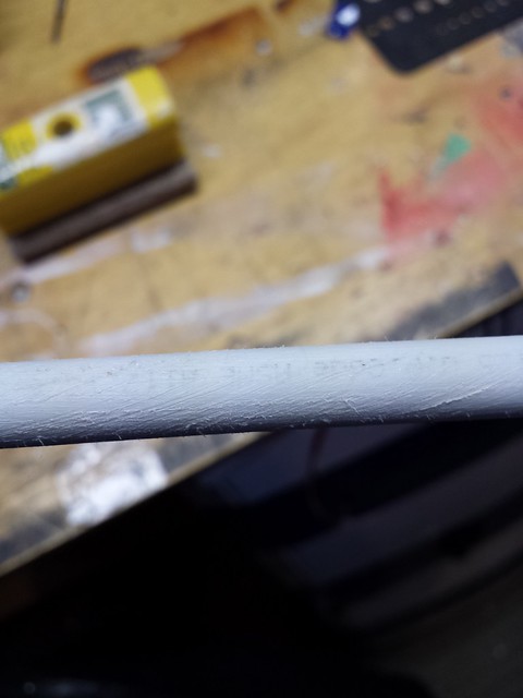
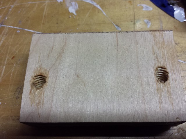
Correct size for 1/4"-20 tab - 13/64" bit.
Drilling through the rear sleeves.
Rear bolt holes drilled and tapped with bolts in for a test fit.
Correct size for 1/4"-20 tab - 13/64" bit.
Drilling through the rear sleeves.
Rear bolt holes drilled and tapped with bolts in for a test fit.
12-23-2013 | 05:20 AM
#31
Thread Starter
Senior Member
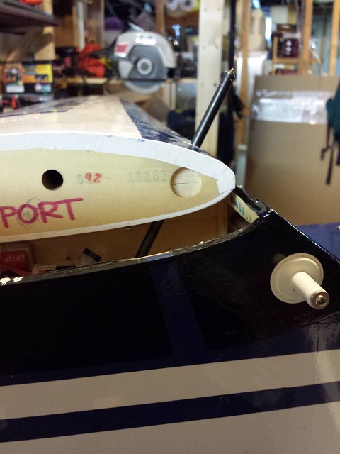
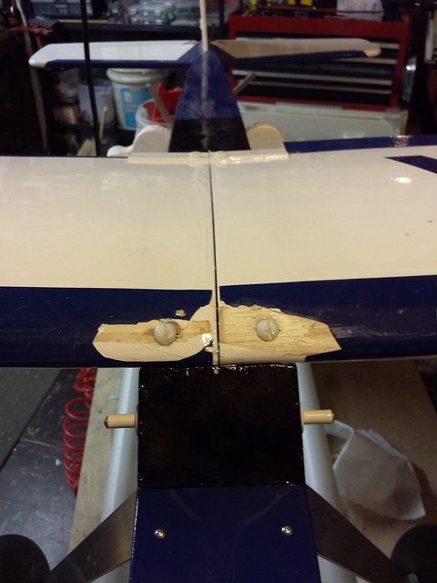
Rear bolts in!
Front bolts in!
You may have noticed that I have done nothing to reinforce the leading edge where the bolts pass through - that's because I really didn't want to open up the wing to add reinforcement. The sleeve prevents the bolt from crushing the wing, although it is only attached by epoxy to the upper and lower skin in the wing. The little voice in my head, which I do try to listen to, told me this was a likely failure point. I decided to try it anyway. When the front bolts were in, I picked up the plane by the wing (near the roots). It held. I tossed the plane a few inches up and caught it by the same place on the wing. It held. Success!
Alas, when I attempted to bore out the sleeve just a little bit for the bolt to slide more easily, the bit torqued the sleeve a little too much, and the little voice was proven right.
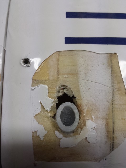
Nothing for it now except to open things up.
Front bolts in!
You may have noticed that I have done nothing to reinforce the leading edge where the bolts pass through - that's because I really didn't want to open up the wing to add reinforcement. The sleeve prevents the bolt from crushing the wing, although it is only attached by epoxy to the upper and lower skin in the wing. The little voice in my head, which I do try to listen to, told me this was a likely failure point. I decided to try it anyway. When the front bolts were in, I picked up the plane by the wing (near the roots). It held. I tossed the plane a few inches up and caught it by the same place on the wing. It held. Success!
Alas, when I attempted to bore out the sleeve just a little bit for the bolt to slide more easily, the bit torqued the sleeve a little too much, and the little voice was proven right.
Nothing for it now except to open things up.
12-23-2013 | 06:07 AM
#32
Thread Starter
Senior Member
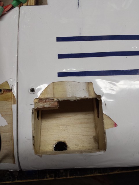
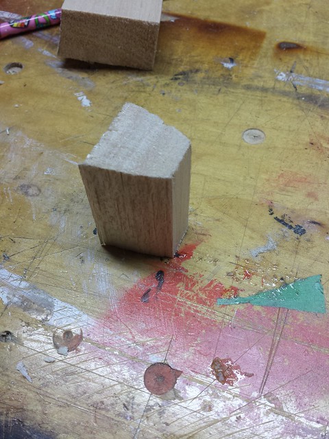
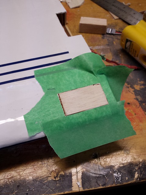
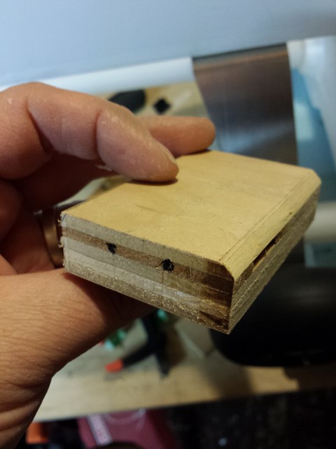
Luckily, I had a big balsa block from when I had to rebuild one of the wingtips on this very wing last winter. Now, even though balsa is technically hardwood (look it up!), it's not especially hard or crush-resistant. However, even the little cautionary voice in my head agrees that this is not a problem - the sleeve will prevent the balsa from being crushed, there is plenty of surface for glue adhesion between sleeve and balsa block, and the balsa block will be glued to the wing on four surfaces.
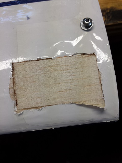
Here's the shaped block.
Glue in, skin on.
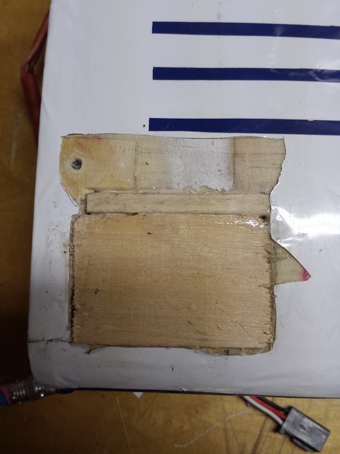
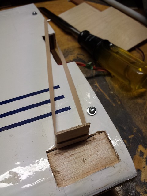
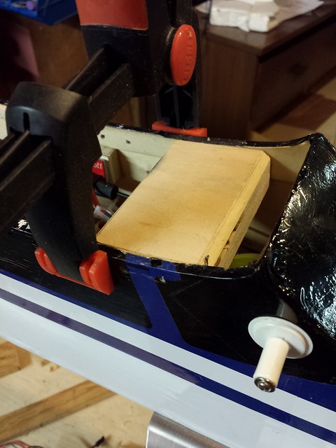
I decided that the other wing would have to be done too. Note the makeshift clamp to hold the balsa block against the internal leading edge.
Next step will be to reattach the wing and drill the new holes.
Here's the shaped block.
Glue in, skin on.
I decided that the other wing would have to be done too. Note the makeshift clamp to hold the balsa block against the internal leading edge.
Next step will be to reattach the wing and drill the new holes.
12-23-2013 | 07:35 AM
#33

Lookin good... Doesn't it follow...every plan when starting never is where it ends up? Another thought, although not a critical one. You might want to put in grommets on the front holes.... just 1/2 on each hole. Since the leading edge is curved and the screw head bottom is flat, the grommet will allow a more spread surface to hold the front.
12-23-2013 | 08:18 AM
#34
Thread Starter
Senior Member
Lookin good... Doesn't it follow...every plan when starting never is where it ends up? Another thought, although not a critical one. You might want to put in grommets on the front holes.... just 1/2 on each hole. Since the leading edge is curved and the screw head bottom is flat, the grommet will allow a more spread surface to hold the front.
 12-27-2013 | 02:10 AM
#36
Thread Starter
Senior Member
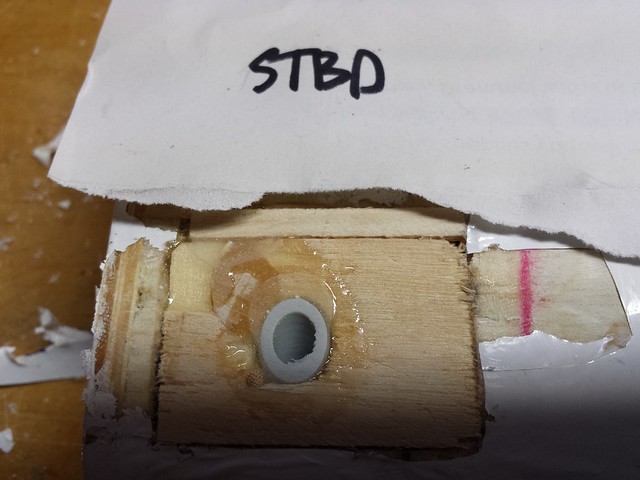
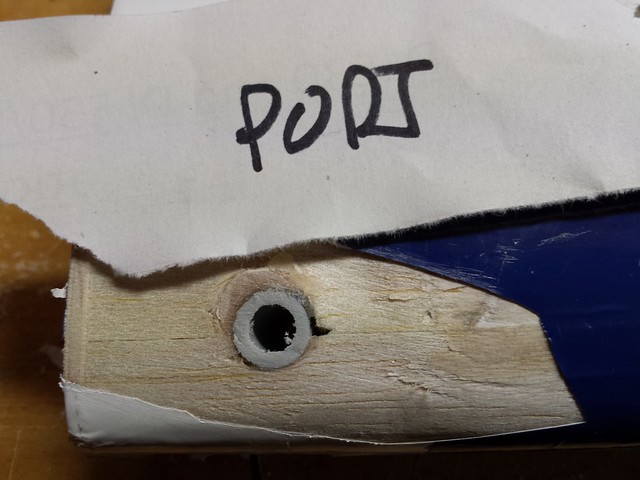
I also fabricated a new forward mount because the original broke while I was working on it. Not a good sign! I had had to remove a considerable amount of the centre section to provide clearance for the forward wing strap and I guess it was just too much.
I removed a layer of ply from the centre section on this mount too. You'll see that a little further down.
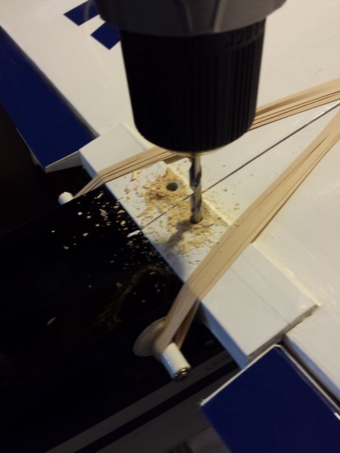
Drilling the wings (again)... Trusty Forstner bit.
Holes drilled.
I removed a layer of ply from the centre section on this mount too. You'll see that a little further down.
Drilling the wings (again)... Trusty Forstner bit.
Holes drilled.
12-27-2013 | 02:16 AM
#37
Thread Starter
Senior Member
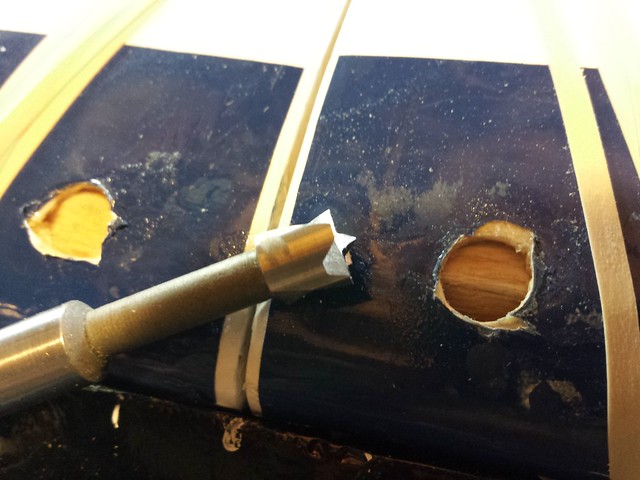
Sleeve material in for an alignment check.
I roughed up the outside of the sleeve to provide better epoxy adhesion.
And although there would be a lot more epoxy contact between sleeve and wing this time, I bored out the sleeve before installing it in the wing.
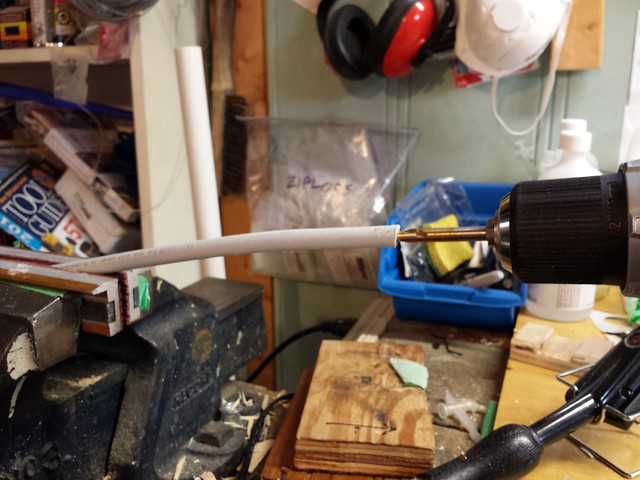
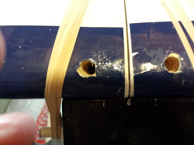
Here's a view of the starboard lower wing surface with epoxy applied.

I roughed up the outside of the sleeve to provide better epoxy adhesion.
And although there would be a lot more epoxy contact between sleeve and wing this time, I bored out the sleeve before installing it in the wing.
Here's a view of the starboard lower wing surface with epoxy applied.

 12-27-2013 | 02:29 AM
#39
Thread Starter
Senior Member
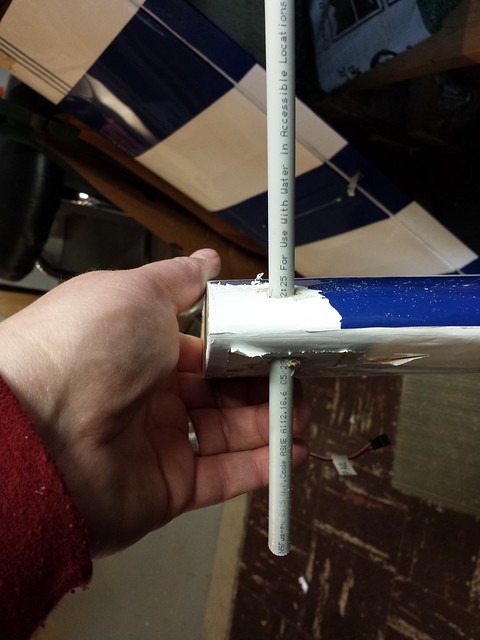
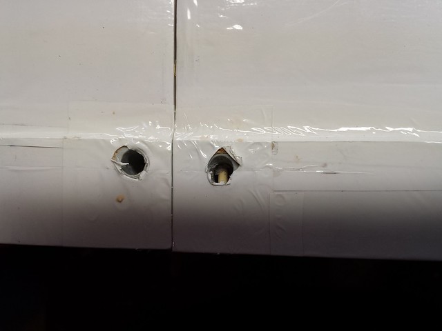
With the wings joined, I bolted them on at the rear and bound them with elastics, hopefully for the last time! You may recall that to tap for 1/4"-20 you need to start with a 13/64" hole. However, the wing tube inner diameter is closer to 1/4". I started by chucking a 15/64" brad point bit in my drill, inserting in the sleeve and running it in reverse to mark a centre point, seen in this photo.
With a centred mark, I switched to the 13/64" bit and bored through the new forward mount to create the wing bolt holes. Note the reduced centre section.
Next step was to chuck the 1/4"-20 tap in the drill and slowly tap the holes...
... followed by some CA for the threads.
With a centred mark, I switched to the 13/64" bit and bored through the new forward mount to create the wing bolt holes. Note the reduced centre section.
Next step was to chuck the 1/4"-20 tap in the drill and slowly tap the holes...
... followed by some CA for the threads.

 12-27-2013 | 02:40 AM
#42
Thread Starter
Senior Member
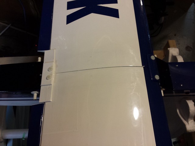
Here's the completed wing. It's been through a lot!
- Extensive damage
- Rebuilding
- Recovering
- Conversion to dual ailerons
and now, conversion to bolt-on.


Before I call this one finished, however, I am going to make a couple of plates - plywood doublers - for the front and back bolt locations. Coming up.
- Extensive damage
- Rebuilding
- Recovering
- Conversion to dual ailerons
and now, conversion to bolt-on.
Before I call this one finished, however, I am going to make a couple of plates - plywood doublers - for the front and back bolt locations. Coming up.
12-30-2013 | 07:30 PM
#43
Thread Starter
Senior Member
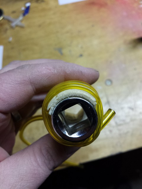
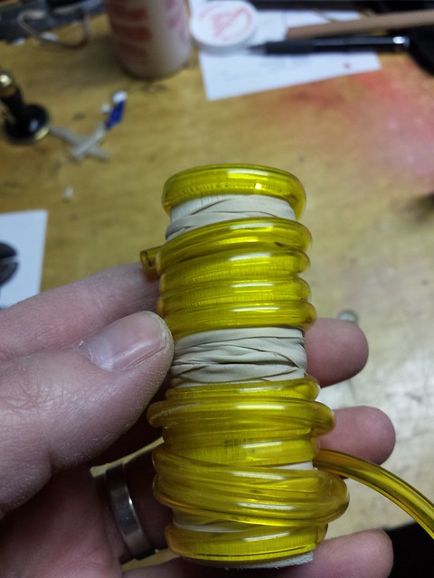
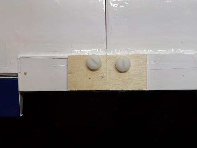
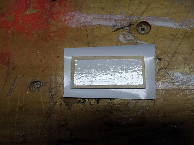
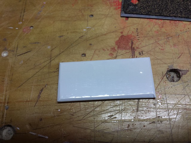
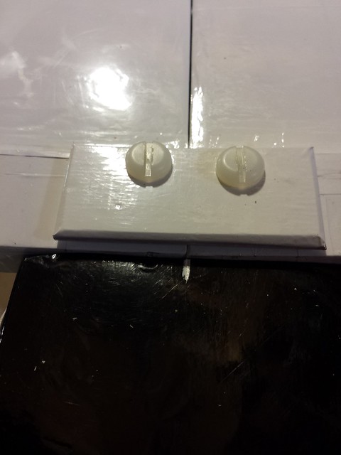
The plates are complete. The front one was the challenge as it had to following the upper curve at the forward edge of the wing. After cutting it to size I put it in some water to soak for 15 minutes or so, then gave it some steam from our Shark portable steamer. I wrapped it around a large socket with rubber bands and some glow fuel tubing.
The two layers delaminated but it was a simple job to add some glue and clamp them back together.

The two layers delaminated but it was a simple job to add some glue and clamp them back together.
12-30-2013 | 07:36 PM
#44
Thread Starter
Senior Member
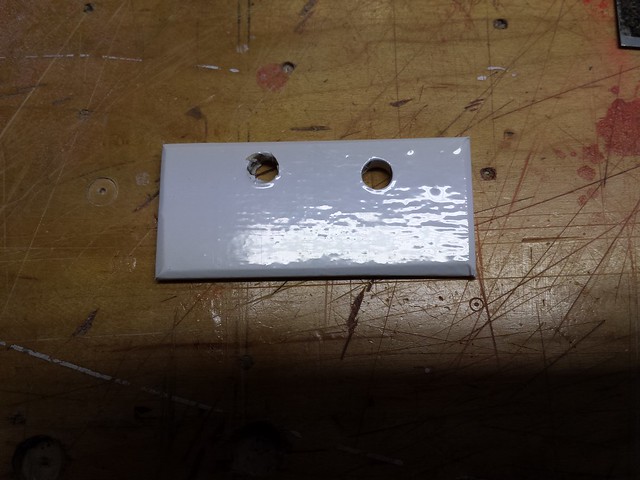
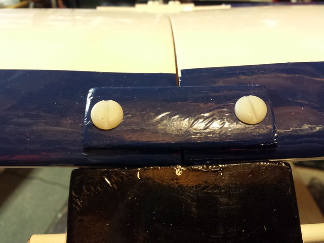
As luck would have it, the fit was good.

One of the rear anti-crush sleeves worked its way loose so I decided to pin both of them with bamboo skewers. I drilled from the back of the wing through the sleeves and glued in the skewers.
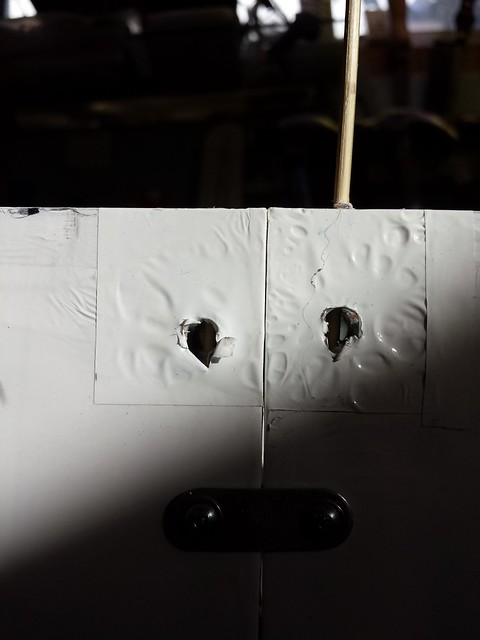
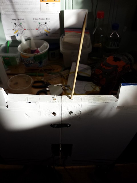
I drilled through the sleeve, removing the inner skewer section so the bolt could pass through again. Now the sleeve is pinned to the surrounding wood in two places.
One of the rear anti-crush sleeves worked its way loose so I decided to pin both of them with bamboo skewers. I drilled from the back of the wing through the sleeves and glued in the skewers.
I drilled through the sleeve, removing the inner skewer section so the bolt could pass through again. Now the sleeve is pinned to the surrounding wood in two places.
 12-30-2013 | 09:41 PM
#47
My Feedback: (1)
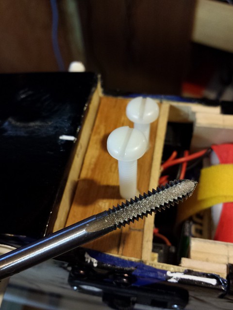
Something that I do to most of my nylon wing bolts may be of value to you. I use a kids hand held pencil sharpener to taper the first 2 or 4 threads on the bottom of the bolt to create "starter threads". With the high angle of the front bolts in relation to the plate in the top of the fuselage some starter threads might help get the "screwing" started. Of course make sure you have enough length. This helps even on bolts not having an angled start.
12-31-2013 | 10:32 AM
#48
Thread Starter
Senior Member
Something that I do to most of my nylon wing bolts may be of value to you. I use a kids hand held pencil sharpener to taper the first 2 or 4 threads on the bottom of the bolt to create "starter threads". With the high angle of the front bolts in relation to the plate in the top of the fuselage some starter threads might help get the "screwing" started. Of course make sure you have enough length. This helps even on bolts not having an angled start.
I've also done a little experimenting with converting the bolt heads from slotted to hex - when I get some more bolts and get the method refined I'll update the post.
12-31-2013 | 08:31 PM
#49
Thread Starter
Senior Member

