


Hidden Hinges Made Easy
 12-17-2006, 03:01 AM
#1
Senior Member
Thread Starter
My Feedback: (1)

Join Date: Jun 2005
Location: Antelope Valley,
CA
Posts: 825
Likes: 0
Received 0 Likes
on
0 Posts
Hidden Hinges Made Easy
Summary
This is an alternative to the usual "V" shaped control surface leading edge. I'm designing my company's first airplane ([link=http://www.rcuniverse.com/forum/m_4588489/mpage_1/key_/tm.htm]Modkat Build Thread: CLICK HERE[/link]) and wanted my hinges to be a little more sophisticated so I developed this easy alternative . I know that scale builders use a similar technique, but I haven't come upon a theard on how to do it so I thought to add one myself. With a little attention to detail, this can be accomplished rather easily and with minimal effort.
Construction
1. Sand the trailing edge of the wing completely flat with a sanding block or razor plane (figure 1).
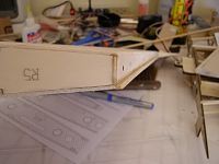
Figure 1
2. Shape the control surface leading edge to a circular shape. Here I used CAD generated templates for guides, but this could be accomplished without them (figure 2).
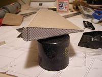
Figure 2
3. Select balsa stringers the same thickness as your wing sheeting and mark, then bevel, approximately 45 degrees away from the edge (figure 3).

Figure 3
4. Attach the stringers to the trailing edge and flush with the wing sheeting. Then, test fit the control surface to the wing and check for binding (figure 4). Here is my set up for the Modkat and the CAD generated plans that I used for a reference (figure 5) [sm=shades_smile.gif].
Mods
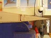

Figures 4 & 5
Summary
This is an alternative to the usual "V" shaped control surface leading edge. I'm designing my company's first airplane ([link=http://www.rcuniverse.com/forum/m_4588489/mpage_1/key_/tm.htm]Modkat Build Thread: CLICK HERE[/link]) and wanted my hinges to be a little more sophisticated so I developed this easy alternative . I know that scale builders use a similar technique, but I haven't come upon a theard on how to do it so I thought to add one myself. With a little attention to detail, this can be accomplished rather easily and with minimal effort.
Construction
1. Sand the trailing edge of the wing completely flat with a sanding block or razor plane (figure 1).
Figure 1
2. Shape the control surface leading edge to a circular shape. Here I used CAD generated templates for guides, but this could be accomplished without them (figure 2).
Figure 2
3. Select balsa stringers the same thickness as your wing sheeting and mark, then bevel, approximately 45 degrees away from the edge (figure 3).
Figure 3
4. Attach the stringers to the trailing edge and flush with the wing sheeting. Then, test fit the control surface to the wing and check for binding (figure 4). Here is my set up for the Modkat and the CAD generated plans that I used for a reference (figure 5) [sm=shades_smile.gif].
Mods
Figures 4 & 5
 12-17-2006, 10:17 AM
#3
Senior Member
My Feedback: (2)
Join Date: Sep 2004
Location: Johns Creek,
GA
Posts: 7,457
Likes: 0
Received 0 Likes
on
0 Posts
Curious what kind of hinge you will use... the stringers would be in the way with any of the "normal" moel hinges that we use..
SO I am really looking forward as to how this will work!
Keep it up!
SO I am really looking forward as to how this will work!
Keep it up!
12-17-2006, 10:43 AM
#4
Senior Member
Thread Starter
My Feedback: (1)
Join Date: Jun 2005
Location: Antelope Valley,
CA
Posts: 825
Likes: 0
Received 0 Likes
on
0 Posts
ORIGINAL: exeter_acres
Curious what kind of hinge you will use... the stringers would be in the way with any of the "normal" moel hinges that we use..
SO I am really looking forward as to how this will work!
Keep it up!
Curious what kind of hinge you will use... the stringers would be in the way with any of the "normal" moel hinges that we use..
SO I am really looking forward as to how this will work!
Keep it up!
Thanks for showing interest,
Mods
12-17-2006, 11:20 AM
#6
Banned
Question: It may be obvious, I do not see a reason for seperate pieces. I just allow the sheeting to extend beyond the vertical member, then use sandpaper warpped over the leading edge of the Aileron to sand the taper.
Les
Les
12-17-2006, 11:50 AM
#7
Senior Member
Thread Starter
My Feedback: (1)
Join Date: Jun 2005
Location: Antelope Valley,
CA
Posts: 825
Likes: 0
Received 0 Likes
on
0 Posts
ORIGINAL: LesUyeda
Question: It may be obvious, I do not see a reason for seperate pieces.
Question: It may be obvious, I do not see a reason for seperate pieces.
I just allow the sheeting to extend beyond the vertical member, then use sandpaper warpped over the leading edge of the Aileron to sand the taper.
Thanks for stating these methods,
Mods
 12-17-2006, 01:31 PM
#10
Senior Member
Thread Starter
My Feedback: (1)
Join Date: Jun 2005
Location: Antelope Valley,
CA
Posts: 825
Likes: 0
Received 0 Likes
on
0 Posts
ORIGINAL: HighPlains
Nice thread (as always) Kelvin. How are you planning on driving the control surfaces?
Nice thread (as always) Kelvin. How are you planning on driving the control surfaces?
How do you seal the gap?
Mods
12-17-2006, 03:44 PM
#12
Senior Member
Thread Starter
My Feedback: (1)
Join Date: Jun 2005
Location: Antelope Valley,
CA
Posts: 825
Likes: 0
Received 0 Likes
on
0 Posts
ORIGINAL: HighPlains
You might try a walking beam. Sorry for the poor image, the file was on an unsupported software, so you get a screen shot.
You might try a walking beam. Sorry for the poor image, the file was on an unsupported software, so you get a screen shot.
Also, if you hit the "print screen" button on the upper right half of the keybord it will take an immediate snapshot of whatever you have on the screen. Paste the file into MS Paint and save it as a jpg. Then you can post it on RCU.
Thanks,
Mods
12-17-2006, 03:56 PM
#13

My Feedback: (1)
What you have is a tube that slides within a tube mounted the the control surface. The ball link is mounted to the servo output wheel, so that neutral has the ball link, hinge line and slide tube all inline. When the servo rotates, the ball link follows and the sliding tube pivots along with the control surface. Since the distance between the ball link and the control surface varies with the angle of the control throw, the tube in a tube has to be able to slide.
I'm building one with a 4-40/2-56 ball link (Dubro 369) threaded onto a 4-40 threaded rod. The T-rod is epoxied into a 5/32" K&S brass tube, and that slides into a K&S 3/16" brass tube that is mounted into the control surface.
CAD away!
I'm building one with a 4-40/2-56 ball link (Dubro 369) threaded onto a 4-40 threaded rod. The T-rod is epoxied into a 5/32" K&S brass tube, and that slides into a K&S 3/16" brass tube that is mounted into the control surface.
CAD away!
12-17-2006, 08:52 PM
#15
I was just busting your chops Kelvin, I never seal my gaps anyway. 
What you're doing is great. A lot of builders have done it in the past, but most people feel it's just too much work.
Now, if you're talking about incorporating it into a kit you plan to market, that would be pretty cool
What you're doing is great. A lot of builders have done it in the past, but most people feel it's just too much work.
Now, if you're talking about incorporating it into a kit you plan to market, that would be pretty cool
12-17-2006, 08:59 PM
#16
Senior Member
Thread Starter
My Feedback: (1)
Join Date: Jun 2005
Location: Antelope Valley,
CA
Posts: 825
Likes: 0
Received 0 Likes
on
0 Posts
ORIGINAL: MinnFlyer
Now, if you're talking about incorporating it into a kit you plan to market, that would be pretty cool
Now, if you're talking about incorporating it into a kit you plan to market, that would be pretty cool
12-18-2006, 10:59 AM
#18
Banned
Hey Kevin. The method works with tapered ailerons, you just have to excersize them as if they were working, i.e., up aileron, down aileron, up aileron, down aileron. Not easy but it does work. The other thing I have done is to hold the aileron in position and slide the sandpaper.
Les
Les
12-18-2006, 12:03 PM
#19
Senior Member

Join Date: Aug 2006
Location: Fort Wayne,
IN
Posts: 223
Likes: 0
Received 0 Likes
on
0 Posts
ORIGINAL: Mods-R-Me
The conventional servo with the arm and control rod sticking out the bottom of the wing. Haven't found a suitable replacement set up that would hide them internally.[sm=confused.gif].
ORIGINAL: HighPlains
Nice thread (as always) Kelvin. How are you planning on driving the control surfaces?
Nice thread (as always) Kelvin. How are you planning on driving the control surfaces?
http://www.irfmachineworks.com/rds/
I've never used this, so have no idea how well it works.
I found that link in this thread:
http://www.rcuniverse.com/forum/m_49...tm.htm#4994370
And here's someone actually installing the thing. Scroll down to the last post on this page, continues on the next page.
http://www.rcgroups.com/forums/showt...e&pagenumber=4
Chris
12-18-2006, 01:01 PM
#20


ORIGINAL: HighPlains
You might try a walking beam. Sorry for the poor image, the file was on an unsupported software, so you get a screen shot.
You might try a walking beam. Sorry for the poor image, the file was on an unsupported software, so you get a screen shot.
I started futzing with this on paper (I'm old enough I still use paper and pencil) and at first I saw a need for a wear bushing of some kind where it exits the training edge. But I got over than when I realized it would be better it didn't contact anything at all prior to the aileron; so a slot would do. But I do think a hinge point near and on on either side would not be a bad idea.
Now I'm really cooking, because I have a semi-symmetrical wing I'm about to begin on and the layout would place the center of rotation above the hinge line. I'm seeing built-in aileron differential in my sketch! Tres cool.
First down side so far is that it has limited throw unless you get the servo wheel right near the T.E.
12-18-2006, 02:13 PM
#21
A walking beam is a great concept. but just not practical.
Below is a scale drawing of an Ultrasport 40+ wing (Rib W-4 where the servo mounts)
As you can see, most High-performance wings are too narrow to allow the servo to be mounted back very far.
This will result in not enough control throw.
PS. if you use a mini servo the results will be the same. Even though you can get it closer to the TE, the wheel has to be smaler to fit inside the tighter quarters.
12-18-2006, 02:24 PM
#22
My Feedback: (1)
Yes Charlie, as your graphic drawings will show, you control the throw of the surface with either the distance to the ball link from the hinge line or by changing the diameter of the servo wheel. Also note, that I have the ball on the far side of the servo, where you can put it on the near side. Differental is also possible by offsetting the location of neutral, but with today's computer radios, it is easier to just do it with the radio. The best part is that it costs about $2 per surface, with $1.50 of that in the ball link. The tollerence of K&S tubing is about .003 so make the tubes as long as possible. They both can extend into the wing all the way to the servo for maximum contact area and minimum slop. Much less wind-up than that angled torque rod approach, plus easier to install.
As far as sealing the gap between the wing and aileron, just fill the gap with vasoline. Move full range and wipe the excess. Have also done the same with a wing/fuselage junction - for high speed models, to cut drag from air moving through the fuselage. Oops, that is a speed secret, don't tell the pylon guys.
As far as sealing the gap between the wing and aileron, just fill the gap with vasoline. Move full range and wipe the excess. Have also done the same with a wing/fuselage junction - for high speed models, to cut drag from air moving through the fuselage. Oops, that is a speed secret, don't tell the pylon guys.
12-18-2006, 03:40 PM
#23
I can see it's not going to work on my current project (which is a relatively thin lower wing from a biplane. I even tried working in a 1" or 1-1/2" aluminum arm extended rearward and cannot gain enough throw with the narrower endpoints that would require (but oh, so close). Back to the old arm out the slotted panel.
I'll file it away for reconsideration in the next thick & full symmertical wing.
I'll file it away for reconsideration in the next thick & full symmertical wing.
12-20-2006, 02:17 AM
#25

ORIGINAL: RC_Fanatic
Check out the Kimbrough drive system:
http://www2.towerhobbies.com/cgi-bin...?&I=LXNN07&P=7
Check out the Kimbrough drive system:
http://www2.towerhobbies.com/cgi-bin...?&I=LXNN07&P=7
http://www.irfmachineworks.com/rds/
These will be used for the ailerons on my TF P-51B project. The project has been delayed longer than anticipated, but I will be continuing the thread mentioned above when I get back to it. I'll be sure to include lots of photos.
http://www.rcuniverse.com/forum/m_49...tm.htm#4994370
Where there's room, the walking beam does look like an inexpensive method to conceal the control rods. Though more expensive, the RDS system allows you to bury the servo farther into the wing where it's deep enough to hold at least a high torque mini servo or even a full size servo.
Scott
