


Extra Extra V2 - Build thread and showcase
 03-03-2009, 03:48 PM
#1
Member
Thread Starter
My Feedback: (2)

Join Date: Sep 2003
Location: Sellersburg,
IN
Posts: 83
Likes: 0
Received 0 Likes
on
0 Posts
Many of you know about and have flown the 71" Extra Extra. Since the initial plane was developed on my CNC foam cutter it was not as good a candidate for others to build especially if they didn't vacuum bag. Thus the EE V2 was born. It's a hybrid fuse that has dual tubes and is 1lb lighter than the foam prototype. This is one stiff fuse with very very little twist!
The plane as it sits is 144.9oz (9.05625lbs, 4.9 wing cube loading). This includes the fuse, wings, linkage, servos (1 HS 85 throttle servo, 4 170oz MG servos, 2.0oz per), APC 18-6W prop, Saito 180 with older heavy muffler (~33oz) , 20oz Dubro fuel tank, CF Troy built wing tube, two 1/2" 55" epoxy/GF tubes (Swany's), 7.3 oz 2700 mah NIMH 6V battery (heavy I know, LION pack in the other plane is 3oz), JW proto landing gear (Swany Aluminum gear on the way to try as well), tail wheel and gear (didn't weigh it separately), Hitec Supreme 8 channel receiver, and all HD servo extensions. Also, a plane has been built in the super light category using an OS 120AX. It came out at ~7lbs 11oz (1383 sq. in, 4.1 wing cube loading)
Current inside rail spacing/clearance is 44mm (1.73") and is sized for a Saito 125-180, YS 110-160, Roto 25 or Evo 26cc gas, or equivalent. It can be opened up from there as the inside clearance to the tubes (mounts are tied/glued into the tubes) is 82.1mm (3.23") .
The prototype plane with the YS 160 (foam sheeted plane) currently weights 9.840625lbs (157.45oz) and it flys as light as a feather. You can see there's a lot of room to play with motor weights. You just might have to move your battery rearward if you put a heavier motor up front.
Nose to tail it is 66.5" long.
Here's a few video links and pictures of finished planes. Build thread to follow....
http://www.youtube.com/watch?v=BIVKgMW3UUs
http://www.youtube.com/watch?v=p7X9I7ZsXxc
http://www.youtube.com/watch?v=UkAPGU5CSYM
http://www.youtube.com/watch?v=G5Vgp_X0oAg
 03-03-2009, 03:57 PM
#4
Member
Thread Starter
My Feedback: (2)
Join Date: Sep 2003
Location: Sellersburg,
IN
Posts: 83
Likes: 0
Received 0 Likes
on
0 Posts
Here's the start of the build pics...
PLEASE READ ALL THE WAY THROUGH THIS BEFORE BEGINNING. ESPECIALLY PAY ATTENTION TO THE SUGGESTED MODIFICATION SECTION.
First you start by gluing the sides together. NOTE: If you are chose the laser cut ply sides the lasers kerf will require that you use a gap filling glue (i.e. gorillla, epoxy, etc.) The sides are dovetailed and made such that they will self align and only go together one way. Once the sides are done add the 3/8" x 1" dowels in the wing bolt locations on the LEFT SIDE FUSE (add these only to the left side!). NOTE: THE LEFT SIDE IS THE SIDE WITH THE SMALLER CUT OUT IN THE MOTOR MOUNT AREA. Use a square to make sure they are perpendicular to the fuse sides.
03-03-2009, 03:59 PM
#5
Member
Thread Starter
My Feedback: (2)
Join Date: Sep 2003
Location: Sellersburg,
IN
Posts: 83
Likes: 0
Received 0 Likes
on
0 Posts
Next you glue the tail and wing subsections together. There are holes in the subsections \for dowels to keep them aligned. The center section is depron so be careful not to use non-foam safe glues. I used foamheasive and was very pleased as I got a strong bond to the balsa and didn't have to wait for the glue to cure.
Next glue them to the left side fuse. On the wing section the wing bolt dowels will align the parts properly but I would also put the wing tube socket in place to make sure it is correct. JUST DON'T GLUE THE SOCKET IN PLACE YET. Add weight to hold it down until it cures.
Glue the tail section on the same way but use the 1/4" dowel locations to align it (I used two 1/4" drill bits (shank end) and removed them after weight was applied). MAKE SURE YOU DON'T GLUE THEM IN.
If you are careful to use the alignment pins the wing to tail incidence should be set at this point.
It's also a good idea to trace the wing and tail sections onto the fuse before you glue them such that you can minimize the glue squeeze out. This will help when you install the tail and wing.
Btw, these pictures show the X bracing top and bottom. They have since been removed (shown in later pictures) as they were proven to not be necessary in most locations.
03-03-2009, 04:01 PM
#6
Member
Thread Starter
My Feedback: (2)
Join Date: Sep 2003
Location: Sellersburg,
IN
Posts: 83
Likes: 0
Received 0 Likes
on
0 Posts
Now the fun begins...former installation. These go in from the tail forward. Once you reach the rear of the wing saddle stop as the next step will be the tube and motor mount installation. If you have the CNC fuse version then make sure you lay all the formers out. They only go in one place but a few are very close in size if you don't pay attention. The laser version are all marked and will match the codes on the fuse. We may label the CNC versions as well later on.
On this step just make sure the tabs are all the way in and you use your square with some quick CA. The process is very fast and accurate this way.
03-03-2009, 04:04 PM
#7
Member
Thread Starter
My Feedback: (2)
Join Date: Sep 2003
Location: Sellersburg,
IN
Posts: 83
Likes: 0
Received 0 Likes
on
0 Posts
Next is the tube installation. Cut the tubes to 55" (I cut them off later in these pictures, it's better to do them first). When cutting the tubes be sure to wrap the cut area in tape to lessen any splintering. After this cut small saw teeth in one end of each tube. These are useful for feeding the tubes through the tightly toleranced former holes. The tubes are captured all the way through the fuse from nose to tail. Once you have the tubes all the way in add some poly glue in the tail section where they contact the side and saddles. You'll add a little more poly glue here when you assemble the other side. Once the poly glue is on spin the tubes back and forth a little to make sure the glue is in good contact between the tube and the saddles. Wetting the balsa and foam slightly before this step will help foam the poly glue a little better and is advisable.
Now you can install the other formers top and bottom of the wing saddles (not the nose yet) . Once this is done glue the tube to the formers where they touch. I just used thin CA here but, if you want and if you work quickly, poly glue or epoxy could be used at the same time you glue the tail saddle in place.
Now check the fit of the motor mounts. If all is well glue them in place to the left side fuse, front wing saddle, and tubes using poly glue or epoxy. Add weight to the motor mounts when gluing to assure proper contact with the fuse sides. while the glue is setting install the remaining formers.
At this point it is a good idea to layout your wire paths and throttle servo location (upper and lower locations precut into the fuse to accommodate different motor carb locations). I did mine later and just melted some of the depron away to get them where I wanted. In some locations it might be good to route away a channel on the outside balsa saddle laminates to make passing the wires through a little easier. Not necessary but I'm sure some of you will find this a better way.
My wires from the tail go under the lower tube and then pass back up past the tubes in the rear wing core out area. This allows you to hide the wires for transparent coverings. You might also be able to route them between the tubes but I haven't, as of yet, tried that.
03-03-2009, 04:05 PM
#8
Member
Thread Starter
My Feedback: (2)
Join Date: Sep 2003
Location: Sellersburg,
IN
Posts: 83
Likes: 0
Received 0 Likes
on
0 Posts
While the glues are setting also reinforce (glass or balsa) the canopy arch joint. This (and some 3/8" square pieces that tie the canopy arch together) will keep it from separating or cracking when you pick the plane up.
03-03-2009, 04:08 PM
#10
Member
Thread Starter
My Feedback: (2)
Join Date: Sep 2003
Location: Sellersburg,
IN
Posts: 83
Likes: 0
Received 0 Likes
on
0 Posts
Once the glues are set (you should be around 1 hour to this point, maybe less) dry fit the other side to this one. You may have to fit some tabs or slots depending on how well you assembled the fuse. Don't worry here. As long as there is a good glue joint at each tab you'll be fine. The main alignment, again, comes from the dowels and tail alignment holes. Also be sure to dry fit the wing tube socket (phenolic tube).
Once you're happy with the fit (be sure it goes on and off fairly easily) add glue to the wing and tail saddles, wing tube to saddle areas (poly, foam safe CA, or epoxy), motor mounts, to the tail and wing tube areas as needed (poly glue), the formers, and assemble the side. Use a slow setting glue as you need a little time to get the glue where you need it. Be sure to keep the glue out of the front and rear anti rotation pin holes (3/8" holes on the wing centerline), the wing tube hole, and the horizontal stab slot. If you get some in there wipe it down. Now glue the wing tube socket (phenolic tube) into the wing with a foam safe glue (poly or epoxy). Be sure not to cut the tube off yet and use a square to make sure it is in proper alignment with the fuse (cut it off after the glues set).
When all is correct glue the tabs to the right side fuse. Go back and check your formers to make sure they are glued to the right side properly. After this is done the wing tube socket can be cut off with a Zona saw and sanded flush.
Next add the 3/8" x 1" (cut from sticks) square stock to the top of the canopy area (all ready precut in the sides). Next glue in the two tail wheel plywood pieces, the tail/rudder hinge cap (1" wide, 1/4" thick) balsa section, and cap the fuse with 1/16" balsa sheeting. Next glue in the two landing gear wooden dowels and sand flush to the fuse.
Now is the time to install the tail and throttle servos and wiring. There are servo trays made for this but I ended up not using them in the tail and just gluing in a ply strip on each end of the servo for the screws to bite into.
One Note: AT THIS POINT DO NOT INSTALL THE RUDDER TRI-STOCK. It will be added after you install the tail surfaces.
Final step, sit back and enjoy you're work! The fuse is complete. Just set it aside for covering and move onto the wings. My total time for the first fuse was 3 hours and that included me slowing down to take pictures. I'm confident this can be done in less than two hours. When you build it send me your times (and comments) as I'm curious to see if I'm correct.
03-03-2009, 04:12 PM
#11
Member
Thread Starter
My Feedback: (2)
Join Date: Sep 2003
Location: Sellersburg,
IN
Posts: 83
Likes: 0
Received 0 Likes
on
0 Posts
Next you can either start the wing or control surfaces. I did the control surfaces and then the wing. This process is really simple as all sticks and cross members are precut for you. Just put them on the plans and thin CA them together. All tail surfaces and ailerons are CNC cut due to their being 3/8" thick. Btw, the leading edge on the tail was just broken and not fully rounded. There was no noticeable difference over the prototype plane so rounding it fully is at the builders discretion. This part of the build goes very fast since you don't have to cut many sticks (just the tri-stock for the hinge lines). Using Rumple Wrap here is awesome to protect the plans plus the parts come right off of it when glued!
03-03-2009, 04:16 PM
#12
Member
Thread Starter
My Feedback: (2)
Join Date: Sep 2003
Location: Sellersburg,
IN
Posts: 83
Likes: 0
Received 0 Likes
on
0 Posts
On to the wing...It's pretty straight forward. BE CAREFUL TO LEAVE ALL SPARS AND WING TUBE SOCKETS OVERHANGING RIB #1 (inside of the wing). THIS IS NECESSARY FOR INSTALLATION OF THE WING ROOT DOUBLER. Now put the lower spar over the plan locations square up and pin in place. Then put the ribs in place square them up (balsa support blocks as shown are useful for this), and pin in place. Install the upper spar using a square (as shown) to make sure the ribs are perpendicular to the build surface. With everything checked for position, fit, and square gently pull the bottom spar upward into position and glue in place with thin CA at each rib position. Repeat on the top spar pushing it gently downward into the ribs. Next install and glue the leading edge making sure to check again for square and straightness of the ribs. After this is complete then install the top front stringers and glue in place with thin CA.
Next install the trailing edge again checking for square and straightness of the ribs. Glue in place with thin CA. Now is the time for the wing tube socket prep and installation. First cut the wing tube socket about 3/8" or so longer than shown on the plan. This will allow you a little extra tube socket beyond the third rib (you only need at most a 1/4" beyond this rib) and a little extra in the inside of the wing that will be sanded flush with the inside root doubler). Next drill a hole in one end of the tube socket that fits a round toothpick. Cut and glue in the toothpick and sand flush with the outside of the tube. Be careful not to sand too much off the tube but make sure the toothpick is not proud of the surface. This feature provides a stop/travel limit so the wing tube can't go too far into the wing during assembly and flight.
Next install the wing tube. First locate the plywood doughnut doublers and install as you slide the tube in the wing. When you install the shear webbing on the main spars (installed after this step) you will need to notch the shear webbing around these doughnut doublers. As the tube passes through each rib slide the plywood wing tube dough nut doublers on the tube. Once you are satisfied with the fit of the wing tube socket (making sure it overhangs/sticks out past rib #1) glue in and the doublers in place with thin CA.
Next install and glue in the shear webbing with the balsa sheet grain running vertically. Using balsa scraps under the sheeting will save you some sanding time on the bottom of the wing (see picture). As you install the balsa shear webbing notch it where the plywood dough nut doublers touch. The pictures show in only going out to the end of the wing tube (which is working well now) but I would recommend going on out to the wing tip (reduces a little potential flex in the wing tip). Slightly dampen the shear webbing behind the wing tube and add a little poly glue such that it will bond the wing tube to the shear webbing. Finally install the trailing edge sheeting. At this point you can slightly taper the trailing edge if you wish but I found it wasn't necessary either visually or functionally if you use thick CA (or poly, see side view picture). I used 1 1/2" wide 1/16" sheeting here. If you are going with the larger engine ranges I would probably change this to 2" sheeting. I also used a straight edge and weights to make sure the sheeting stayed down on the ribs. Next install the L.E. sheeting and rib cap sheeting. Again, leave a little overhang on the inside of the wing. Now install the inside root sheeting between rib #1 and rib #1. Again, leave a little overhang on the inside of the wing.
Next, remove the wing from the table and install the wing root doubler (has the tab). MAKE SURE WHEN YOU GLUE THE R1 DOUBLER ON THIS WING YOU ORIENT IT TO MAKE A OPPOSITE SIDE WING!
Look at the tabs, match them to the fuse pattern, and make sure you glue it on accordingly (two tabs are on the top side of the wing, pictures show an earlier version wing that only has 1 top tab). Once your happy with the fit glue it in place. Finally, turn the wing over and install the bottom side leading edge, trailing edge, and rib cap sheeting. Sand the ends flush and install the wing tip doubler. Sand the leading edge to shape. Templates are provided (if you want to use them as a guide) for the inside, middle, and outside rib leading edge profiles. Install the servo rails and tray (many options here are possible, see photos for how I did mine). Install and glue the trailing edge tri-stock in place.
Repeat for the other wing. Install any hatches you may wish to use. On my planes all I install is a balsa doubler to the inside of the root sheeting for the charge jack/switch as there is easy access to the radio gear from the inside edge of the wing.
03-03-2009, 04:31 PM
#14
Member
Thread Starter
My Feedback: (2)
Join Date: Sep 2003
Location: Sellersburg,
IN
Posts: 83
Likes: 0
Received 0 Likes
on
0 Posts
On to the final assembly...
Be sure to add 3/8" thickness doublers at all hinge locations just to be sure you have enough meat for the hinges. Some locations will not require this but check to be sure.
Cover all surfaces. To install the horizontal stabilizer cut a small section from the rudder vertical support. I cut this section in a wedge that gets tighter as it is pulled to the tail (for additional strength once it's glued back in). When cutting this section plan ahead for your rudder hinge locations and keep the cut out of these areas and where you can still get the h-stab and elevator in place. Once happy with the fit add glue and slide the h-stab in and square and true it to the fuse. A square on the fuse and against the stab will help as well as checking the front (or rear) outside h-stab tip distance to the rear wing anti rotation hole locations. Once this is done slide the elevator in and hinge it in place. Re-glue the piece you cut from the vertical rudder support back in place.
Next glue the vertical stabilizer in place keeping it on the fuse center line and parallel to the sides. Glue in tri-stock supports on the sides of the vertical stab where it meets the fuse.
At this point add the rudder tri-stock and cover. Hinge and install the rudder. Install a tail wheel of your choice.
Installation of landing gear is done by pre-drilling the proper size holes for the screws you plan on using (6-32 recommended) in the landing gear support dowels in the fuse. Then drill corresponding holes in both landing gear. Gear choice should be selected based on a 7-10 lb aircraft weight (due to motors ranging from 125 class motors to Gas Rail Mount Engines). Suggested gear are Swany's Mojo 65 Aluminum Gear, Graftech carbon fiber gear, JW high strength gear (hard to get), and Tetherite 90 size or giant scale gear.
Install the engine and fuel tank. Depending on your motor you may need to chamfer the mounts a bit for a good motor to rail fit. The motor mounts are designed with room to enlarge the space between them for larger motors. Just double check your clearance with the tubes. If the tubes will be hit by your motor mount bolts (has not yet been needed with engines up to a Satio 180 and YS 160DZ) glue a dowel inside the tubes where the bolt will pass through. This should maintain the structural integrity of the nose.
The fuel tanks are typically installed with eye hooks in the fuse above and below the tank. Be sure to center your tank on the fuse centerline. Put foam behind the tank and secure with either rubber bands or zip ties. Finish by plumbing the plane with fuel tubing.
Install all servos using 160oz+ servos on the tail and wings and a HS-85MG or similar for the throttle (per cut throttle hole can be enlarged for full size servo if desired). Use heavy duty control surface horns such as these Dubro options: http://www3.towerhobbies.com/cgi-bin...?&I=LXDCU2&P=7
http://www3.towerhobbies.com/cgi-bin...?&I=LXEMF7&P=7
Use heavy duty push rods (carbon push rods preferred, 4-40 has been used successfully on the ailerons. Add main gear wheels and axles.
03-03-2009, 05:02 PM
#15
Member
Thread Starter
My Feedback: (2)
Join Date: Sep 2003
Location: Sellersburg,
IN
Posts: 83
Likes: 0
Received 0 Likes
on
0 Posts
Finally, make two small pieces out of 1/4" ply, cover, and install/glue on the left side wing mounting tabs for a blind nut to bite into. Then pre-drill the holes in the fuse for the wing mounting bolts. Slide the wings on one at a time and drill wing mounting tab holes into each wing by drilling through the fuse using it as a guide.
Now is the time to measure the wing tube length and cut it off. Put the tube in one wing and slide it onto the fuse. Once seated make sure the tube is all the way in the wing. The take a pencil and draw a circle around the tube on the opposite side of the fuse. Also mark the tube sides left and right so you don't make a mistake in the next step. Now slide the wing off leaving the wing tube in the fuse. Slide the opposite wing into place and mark the wing tube on the opposite side of the fuse. Remove the wing and tube and measure the distance between the two marks. Add 1/32 to 1/64 to this measurement and then cut the tube by this amount. Next install your wings by sliding them onto the wing tube and anti-rotation pins, tighten the wing bolts, and then double check your CG with all equipment in place. Right now the suggested CG is designed at 8-9 1/4" back from the L.E. at the root. I need to check the plane again as the current CG is perfect. I'll check that and post it as soon as I can. I also used foam tape on the inside of the wing doubler to help dampen vibration. I don't think it's necessary but seems to have worked well.
The last thing you need to do is read the following articles and realize you may have the same thing happen to you when you fly this plane. After all , this plane was designed to make the news...
I know, I know, sometimes I spend too much time online
03-03-2009, 05:08 PM
#16
Member
Thread Starter
My Feedback: (2)
Join Date: Sep 2003
Location: Sellersburg,
IN
Posts: 83
Likes: 0
Received 0 Likes
on
0 Posts
These mods are suggested especially on the contest grade models several are building.
Contest Grade reinforcements:
Glassing of the center h-stab section with Carbon fiber laminate on the h-stab and elevator l.e. pieces ...and/or sheeting of the h-stab (all new kits will have these mods build in).
The elevator and ailerons need ply doublers and dowel reinforcements. The elevator ply doubler is 1/16" x 5/8" x 8" top and bottom. The aileron ply doublers should be 1/16" x 5/8" x 1" (top and bottom). The dowels you need are as follows:
3 - 1" x 3/8" dia. ( wing bolt locations)
2 - 2" x 3/8" dia. (anti rotation and fuse tie in dowels)
4 - 3/8"x 3/8"dia. dowels - Control horn reinforcements
1 - 1" x 3/4" dia. - Bottom LG mount
1 - 1" x 1/2" dia. - Top LG mount
Hinging No No's - See the picture. Keep your hinges away from a control horn location. I had one about 1/4" away and it cracked. I put in another corner triangle gusset in the horizontal stab (see pic) and that fixed the problem. That might not be a bad thing to go ahead and do anyway.
You may all ready have a tail wheel but, if not, here's the one I used and really like it. It's a bit expensive but well worth IMHO.
http://www.hobby-lobby.com/landinggear.htm
I used the middle one: SCE040 Tailgear Assembly, 3-1/4" x 4-1/2" with 1-1/2" Deluxe Kavan Wheel ..... $ 25.90
On the ailerons....don't forget to modify the inboard side. It needs to be shortened (from the fuse outward) by 3/8". I just laid a 3/8" stick over them (after I put them down on the plans) cut them that much, and glued a new end piece and triangle braces in place. Also, don't forget to add the hinge location doublers at all hinge locations (see pic) and the diagonal braces.
As each one goes through the build it I would appreciate any feedback you may have (good or bad) as I'm always looking to improve this plane. Also, you will have a few things different than the build thread mainly in the addition of third wing bolt /ear location at the L.E. (I just believe it will make the plane last longer, less stress on the inboard doubler). All kits now include that change. You also will have some extra parts (ear doublers so the lock nuts have something to bite into) so let me know if it's not clear.
Finally, in all the kits I am including laser cut foamy motor mounts. I had some free plywood space so I figured why not. If you don't fly foamys give them to someone who does.
Pictures below should help clarify these changes.
03-03-2009, 05:10 PM
#17
Member
Thread Starter
My Feedback: (2)
Join Date: Sep 2003
Location: Sellersburg,
IN
Posts: 83
Likes: 0
Received 0 Likes
on
0 Posts
ORIGINAL: wessco
For anyone interested, how do you go about getting one of these?
For anyone interested, how do you go about getting one of these?
03-04-2009, 08:01 AM
#18
Senior Member
Join Date: Jul 2006
Location: Charlottesville,
VA
Posts: 723
Likes: 0
Received 0 Likes
on
0 Posts
Can I play too???  I’m just finishing mine up. I'm using an OS 120 AX, which is rated at about the same output as the big Saito, 3HP or so, but I’m pretty certain the 180 will swing a bigger prop and make more usable thrust. Because of this, I tried to shave as much weight as reasonably possible. Based on a few estimates, I set my AUW goal at 8 pounds even. In the end, however, the result is 7 pounds 11 ounces. This is 22 ounces, or 15%, less than both Brian's (guinnb) plane, at 9 pounds 1 ounce. With a full load of fuel (10 ounces), my take-off weight will be 8 pounds 5 ounces. Unless I’m mistaken, Brian runs a 20-ounce tank, yielding a take-off weight of 10 pounds 5 ounces, for a difference of exactly 2 pounds. I know 10 ounces won’t buy much flight time, but I’ve got 12 and 16-ounce tanks standing by and ready to go. Again, for the moment, the lowest weight is the priority.
So, how the heck did this thing end up 22 ounces lighter, you ask? Primarily, it’s through choice and placement of components. Here’s the rundown.
ENGINE
The OS is 4 ounces lighter than the big Saito. I mounted it as far back as I could on the rails and still had no problems with CG.
ENGINE RAILS
In addition to the standard oak engine bearers, Brian provided a set of maple bearers. He knew I was going for light weight and volunteered to help. The oak ones weighed 4.1 ounces and the maple only 2.0, so that’s another 2.1 ounces.
PROP
Brian used the APC 18x6W at 4.6 ounces. I’m using a JXF/Xoar 17x6 at 2.6 ounces, yielding another 2 ounces.
BATTERY
Brian used a 7 ounce lipo/reg setup and I used an 1100 mah A123 pack. Capable of delivering 30 amps, fast recharging between flights with the CellPro and weighing only 3 ounces, it seems like a win/win/win. That’s another 4 ounces saved. Also, it’s mounted in the fuse right above the engine as far forward as possible.
LANDING GEAR
Because I ws shooting for 8 pounds, I decided to try out a pair of 90-size Tetherites. At only 4 ounces, they are 4.5 ounces lighter than the aluminum gear I got from Brian. Also, instead of a conventional tailwheel assembly, I used a music wire skid. While I couldn’t find a weight to use for comparison, a conservative guess on the weight of such an assembly is 1.5 ounces. The skid weighs less than 1/2-ounce, so we’ll call it a savings of 1 ounce.
For those scoring at home, you’ve already figured out the total so far is about 17.6 ounces. You might have also noticed that the majority of the weight came off the nose of the plane. This opens the door to a potentially tail heavy situation. Before I even glued the first stick on this kit, I talked to Brian about removing some extra wood from the tail. Using his suggestions, I took a little over 2 ounces of lite ply out of the tail, bringing the total savings to damn near 20 ounces.
The final weight saving step was to use painted Doculam instead of conventional covering. I bought two 500-foot rolls of this stuff and don’t plan on buying any more covering material for at least a lifetime or two. For the tail surfaces, I just left the covering clear because I still wasn’t sure I wouldn’t come out a little tail heavy. The plane is now fully covered and awaiting final assembly. The weight of all components is 7 pounds 10 ounces, but I figure there might be some little last minute things that creep in, so I’m calling it 7 – 11.
Since Brian already posted tons of pics, I’ll only show little things I did differently. Some changes were made for weight savings, but some were just personal preferences, even if they added weight instead of saved it. To me, that’s the best part about building; being able to do your own thing.
As designed, the root ribs are 1/8-inch lite ply with doublers where the mounting screws go through. For someone who doesn’t crash as much as me, I’m sure this is more than adequate. Based on my experience with the Sabre 56, however, the lite ply won’t last long for me. I put a layer of 1/32-inch aircraft ply on either side of the stock pieces. I picked up an ounce doing this, but they are now VERY stiff and will hopefully be worth the extra weight.
I also changed the way the rudder and elevator control horn mounting points are reinforced. The kit includes some perfectly adequate doublers, but I wanted a little more durability. I used more 1/32-inch aircraft ply along with some “heat-tac” carbon fiber like the kind Pauly supplies with the MoJo kits. These changes, in conjunction with 1/2-inch oak hard points, makes for bullet-proof hard-points.

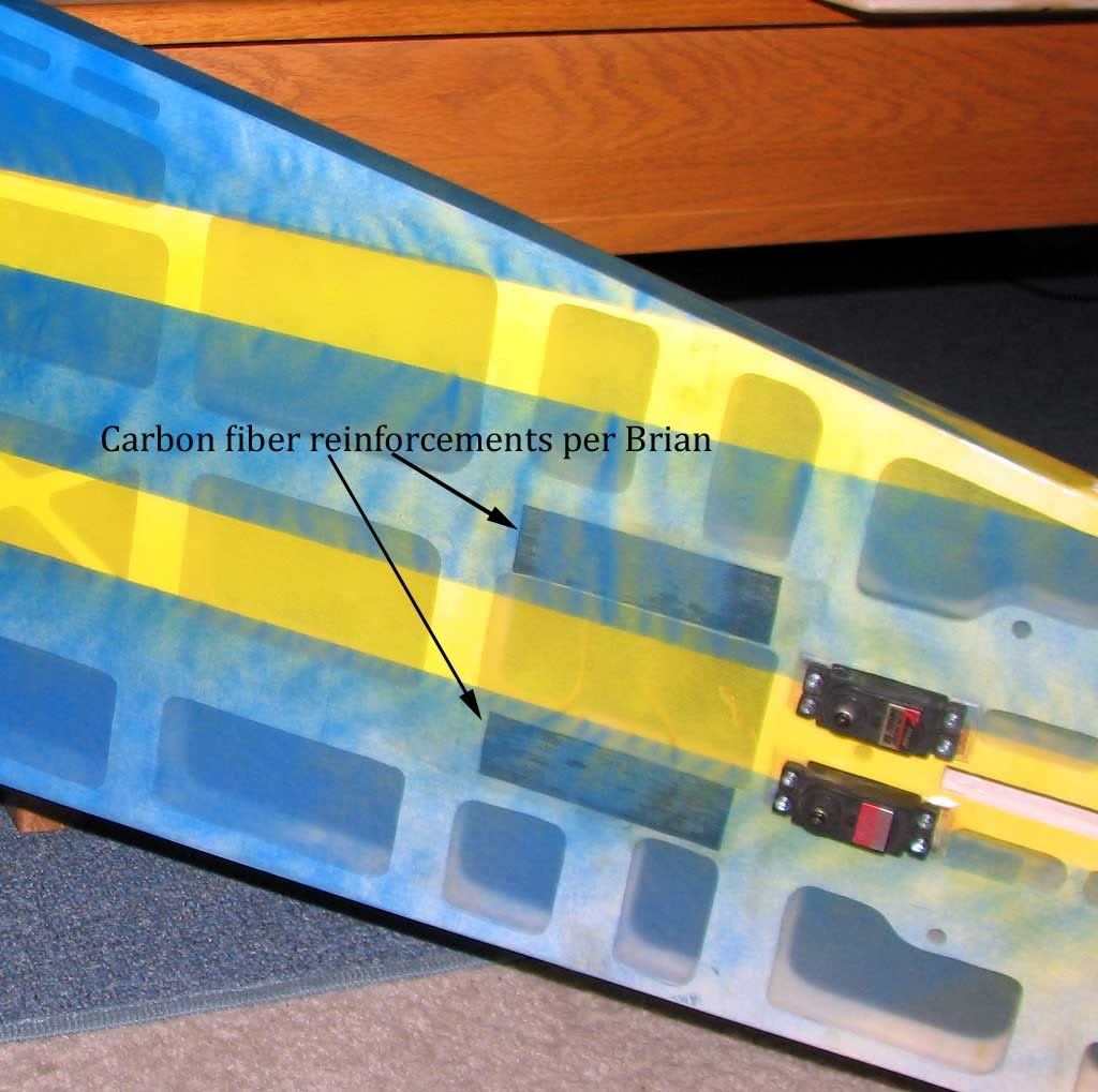
Brian suggested beefing up the stab a bit, so I laid in two 24-inch pieces of carbon fiber rod and more heat-tac CF on the center section. I also used some carbon fiber tow and ca’d it around the perimeter of both the rudder and elevator. If I were doing this again, the tow would go under the ply doublers and I would use epoxy instead of CA.
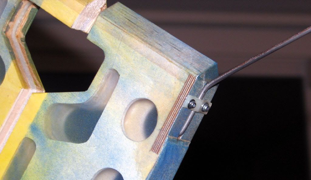
Because of all the wood I removed from the tail, Brian suggested reinforcing the fuse seams just forward of the tail servos. I used epoxy and heat-tac CF in this area as well.
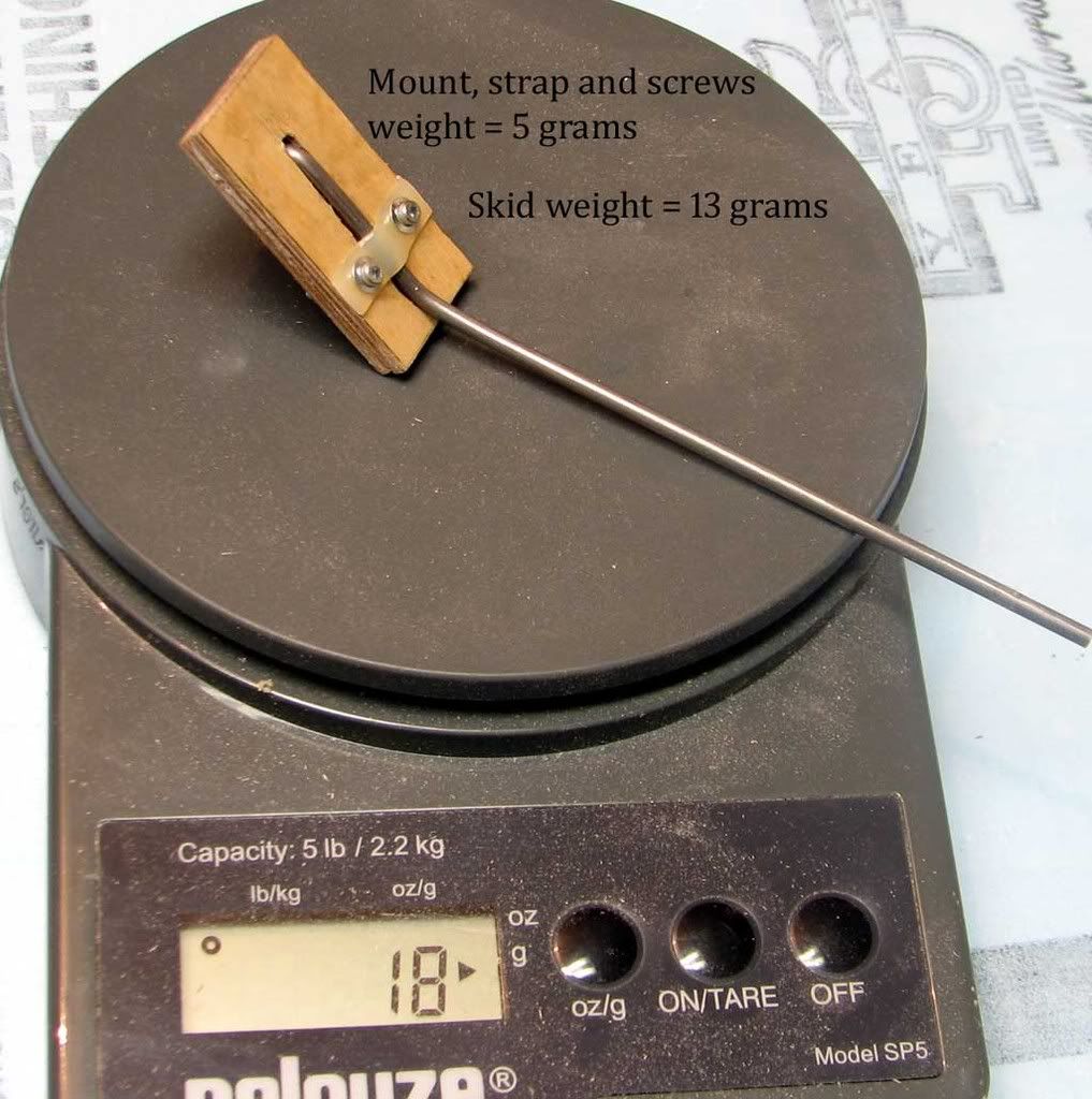
Here is a pic of the tail-skid assembly I came up with. As noted above, the weight of the skid is only 13 grams and I think it will last far longer than the plane.
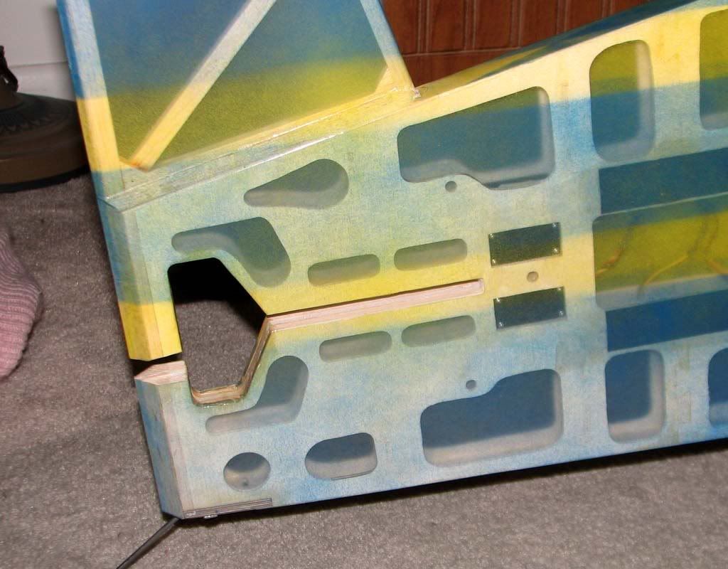
Here is a shot showing the extent of the lightening I did in the tal. If you compare this to some of the pics above, you can see exactly how much I took out. It’s also obvious that I went as light as possible with the paint in the tail.
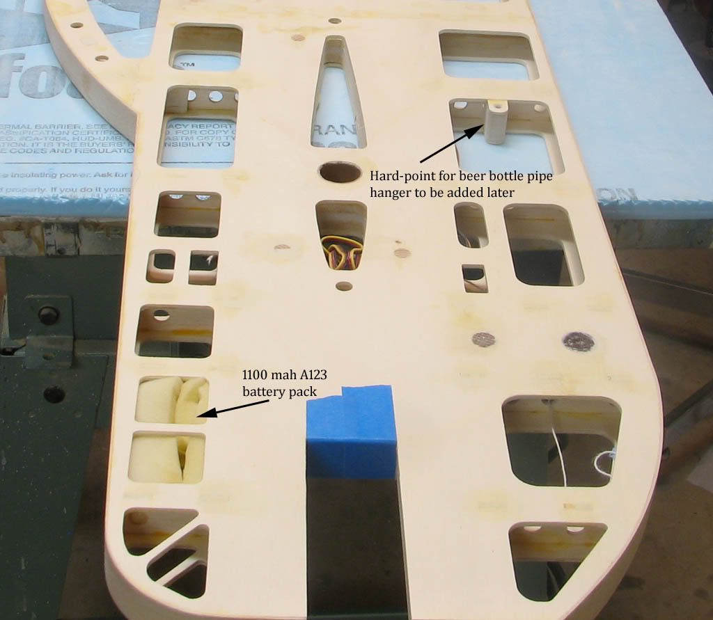
This one shows the location of the battery and the hard point I made for future use with the beer bottle pipe.
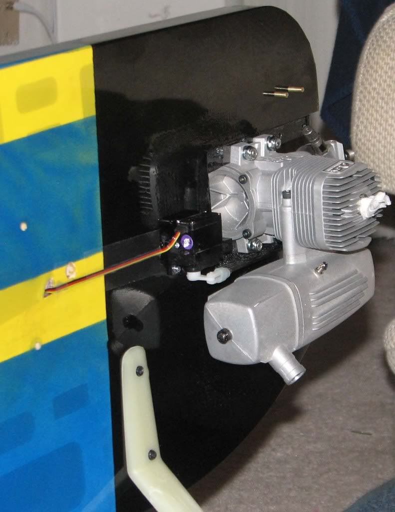
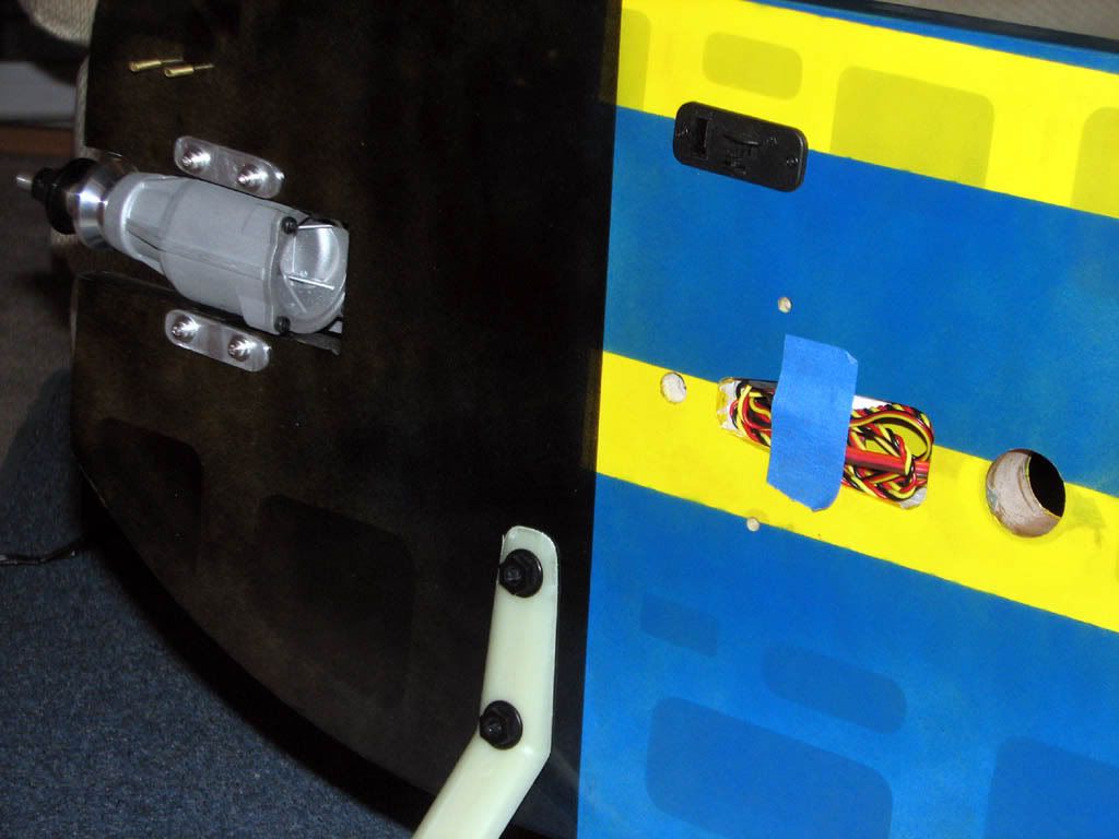
Finally, here are just a few general shots showing some of the details. On the nose, I moved the throttle servo forward to maximize its effect on the CG. Also note that the right LG leg has been drilled and tapped for 1/4-20 nylon bolts, thereby negating the need for nuts. If the Tetherite material gets stripped, I can always use new bolts and throw a couple of nuts on there. I didn’t spare the paint up here and I think the opacity of the covering turned out pretty good.
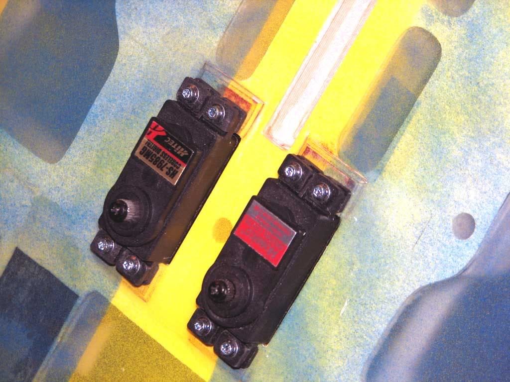
This is just a shot of the tail servos. I cut little rectangles of 1/16-inch aircraft ply for mounting tabs and sanded bevels on the edges to aid in covering.
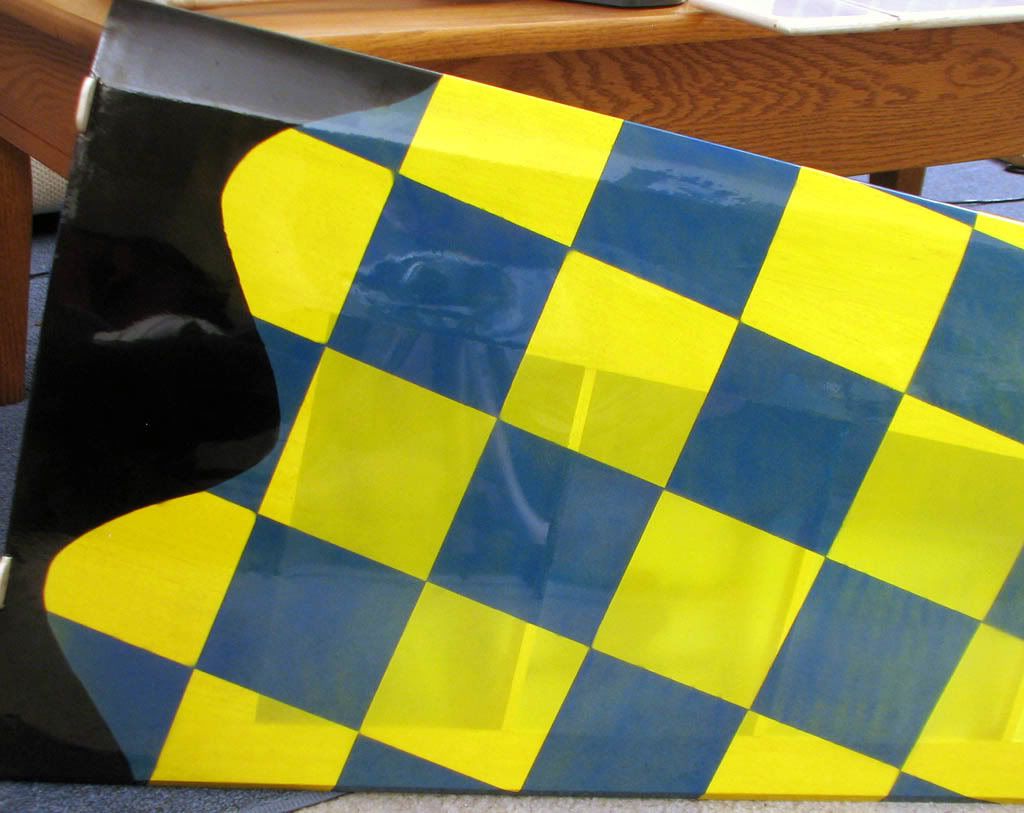
Here is a shot of one of the wings. I’m still trying to get the hang of painting the Doculam with clean edges. You can see some overspray around some of the edges. Overall, however, it looks pretty good from 10 feet away.
I’ll post a completed pic after I get the thing totally put together. The bottom of the wings are totally clear at this point, but I have a set Pro Bro letters cut by Gator that will be going on soon. This kit has been a joy to build. As with any new design, there were a few kinks to work out, but anyone considering one of these shouldn’t hesitate to take the plunge. Brian is more than willing to offer guidance and personal service. You couldn’t ask for better.
I’m just finishing mine up. I'm using an OS 120 AX, which is rated at about the same output as the big Saito, 3HP or so, but I’m pretty certain the 180 will swing a bigger prop and make more usable thrust. Because of this, I tried to shave as much weight as reasonably possible. Based on a few estimates, I set my AUW goal at 8 pounds even. In the end, however, the result is 7 pounds 11 ounces. This is 22 ounces, or 15%, less than both Brian's (guinnb) plane, at 9 pounds 1 ounce. With a full load of fuel (10 ounces), my take-off weight will be 8 pounds 5 ounces. Unless I’m mistaken, Brian runs a 20-ounce tank, yielding a take-off weight of 10 pounds 5 ounces, for a difference of exactly 2 pounds. I know 10 ounces won’t buy much flight time, but I’ve got 12 and 16-ounce tanks standing by and ready to go. Again, for the moment, the lowest weight is the priority.So, how the heck did this thing end up 22 ounces lighter, you ask? Primarily, it’s through choice and placement of components. Here’s the rundown.
ENGINE
The OS is 4 ounces lighter than the big Saito. I mounted it as far back as I could on the rails and still had no problems with CG.
ENGINE RAILS
In addition to the standard oak engine bearers, Brian provided a set of maple bearers. He knew I was going for light weight and volunteered to help.
The oak ones weighed 4.1 ounces and the maple only 2.0, so that’s another 2.1 ounces.PROP
Brian used the APC 18x6W at 4.6 ounces. I’m using a JXF/Xoar 17x6 at 2.6 ounces, yielding another 2 ounces.
BATTERY
Brian used a 7 ounce lipo/reg setup and I used an 1100 mah A123 pack. Capable of delivering 30 amps, fast recharging between flights with the CellPro and weighing only 3 ounces, it seems like a win/win/win. That’s another 4 ounces saved. Also, it’s mounted in the fuse right above the engine as far forward as possible.
LANDING GEAR
Because I ws shooting for 8 pounds, I decided to try out a pair of 90-size Tetherites. At only 4 ounces, they are 4.5 ounces lighter than the aluminum gear I got from Brian. Also, instead of a conventional tailwheel assembly, I used a music wire skid. While I couldn’t find a weight to use for comparison, a conservative guess on the weight of such an assembly is 1.5 ounces. The skid weighs less than 1/2-ounce, so we’ll call it a savings of 1 ounce.
For those scoring at home, you’ve already figured out the total so far is about 17.6 ounces. You might have also noticed that the majority of the weight came off the nose of the plane. This opens the door to a potentially tail heavy situation. Before I even glued the first stick on this kit, I talked to Brian about removing some extra wood from the tail. Using his suggestions, I took a little over 2 ounces of lite ply out of the tail, bringing the total savings to damn near 20 ounces.
The final weight saving step was to use painted Doculam instead of conventional covering. I bought two 500-foot rolls of this stuff and don’t plan on buying any more covering material for at least a lifetime or two.
For the tail surfaces, I just left the covering clear because I still wasn’t sure I wouldn’t come out a little tail heavy. The plane is now fully covered and awaiting final assembly. The weight of all components is 7 pounds 10 ounces, but I figure there might be some little last minute things that creep in, so I’m calling it 7 – 11. Since Brian already posted tons of pics, I’ll only show little things I did differently. Some changes were made for weight savings, but some were just personal preferences, even if they added weight instead of saved it. To me, that’s the best part about building; being able to do your own thing.
As designed, the root ribs are 1/8-inch lite ply with doublers where the mounting screws go through. For someone who doesn’t crash as much as me, I’m sure this is more than adequate. Based on my experience with the Sabre 56, however, the lite ply won’t last long for me. I put a layer of 1/32-inch aircraft ply on either side of the stock pieces. I picked up an ounce doing this, but they are now VERY stiff and will hopefully be worth the extra weight.
I also changed the way the rudder and elevator control horn mounting points are reinforced. The kit includes some perfectly adequate doublers, but I wanted a little more durability. I used more 1/32-inch aircraft ply along with some “heat-tac” carbon fiber like the kind Pauly supplies with the MoJo kits. These changes, in conjunction with 1/2-inch oak hard points, makes for bullet-proof hard-points.
Brian suggested beefing up the stab a bit, so I laid in two 24-inch pieces of carbon fiber rod and more heat-tac CF on the center section. I also used some carbon fiber tow and ca’d it around the perimeter of both the rudder and elevator. If I were doing this again, the tow would go under the ply doublers and I would use epoxy instead of CA.
Because of all the wood I removed from the tail, Brian suggested reinforcing the fuse seams just forward of the tail servos. I used epoxy and heat-tac CF in this area as well.
Here is a pic of the tail-skid assembly I came up with. As noted above, the weight of the skid is only 13 grams and I think it will last far longer than the plane.
Here is a shot showing the extent of the lightening I did in the tal. If you compare this to some of the pics above, you can see exactly how much I took out. It’s also obvious that I went as light as possible with the paint in the tail.
This one shows the location of the battery and the hard point I made for future use with the beer bottle pipe.
Finally, here are just a few general shots showing some of the details. On the nose, I moved the throttle servo forward to maximize its effect on the CG. Also note that the right LG leg has been drilled and tapped for 1/4-20 nylon bolts, thereby negating the need for nuts. If the Tetherite material gets stripped, I can always use new bolts and throw a couple of nuts on there. I didn’t spare the paint up here and I think the opacity of the covering turned out pretty good.
This is just a shot of the tail servos. I cut little rectangles of 1/16-inch aircraft ply for mounting tabs and sanded bevels on the edges to aid in covering.
Here is a shot of one of the wings. I’m still trying to get the hang of painting the Doculam with clean edges. You can see some overspray around some of the edges. Overall, however, it looks pretty good from 10 feet away.
I’ll post a completed pic after I get the thing totally put together. The bottom of the wings are totally clear at this point, but I have a set Pro Bro letters cut by Gator that will be going on soon. This kit has been a joy to build. As with any new design, there were a few kinks to work out, but anyone considering one of these shouldn’t hesitate to take the plunge. Brian is more than willing to offer guidance and personal service. You couldn’t ask for better.
03-04-2009, 09:05 AM
#21
Senior Member
My Feedback: (7)
Join Date: Apr 2005
Location: Summerville,
GA
Posts: 493
Likes: 0
Received 0 Likes
on
0 Posts
ORIGINAL: JustErik
Those are the small ones!
ORIGINAL: wessco
Reckon those pictures could be any bigger?
Reckon those pictures could be any bigger?
You got life size pictures as well?
03-07-2009, 08:36 AM
#23
Senior Member
Join Date: Jul 2006
Location: Charlottesville,
VA
Posts: 723
Likes: 0
Received 0 Likes
on
0 Posts
ORIGINAL: wessco
JustErik...it's the weekend, are you ready to fly this thing?
JustErik...it's the weekend, are you ready to fly this thing?
This weekend is somewhat busy, but with a little luck, I should be able to get it in the air next week some time.
03-10-2009, 10:21 AM
#24
Member
Thread Starter
My Feedback: (2)
Join Date: Sep 2003
Location: Sellersburg,
IN
Posts: 83
Likes: 0
Received 0 Likes
on
0 Posts
ORIGINAL: JustErik
Damn near.....just need to get the rudder hinged, servos screwed in, linkages installed and RX wedged in place. I should also probably slap some vinyl on the bottom side of the wing before I get it all oily. This weekend is somewhat busy, but with a little luck, I should be able to get it in the air next week some time.
ORIGINAL: wessco
JustErik...it's the weekend, are you ready to fly this thing?
JustErik...it's the weekend, are you ready to fly this thing?
This weekend is somewhat busy, but with a little luck, I should be able to get it in the air next week some time.
Can't wait to get a flight report with the 120AX! Watch out for thermals with the wing loading you're at....[sm=75_75.gif][sm=shades_smile.gif]
03-10-2009, 10:23 AM
#25
Senior Member
My Feedback: (7)
Join Date: Apr 2005
Location: Summerville,
GA
Posts: 493
Likes: 0
Received 0 Likes
on
0 Posts
What engine to get for one is going to be a tough decision. I flew the white Colts Extra, Extra and really liked it...although my knees were knocking way to bad to be trying to fly a plane that wasn't mine.