


BVM Bobcat Composite rebuild
 10-06-2019, 07:44 PM
#1


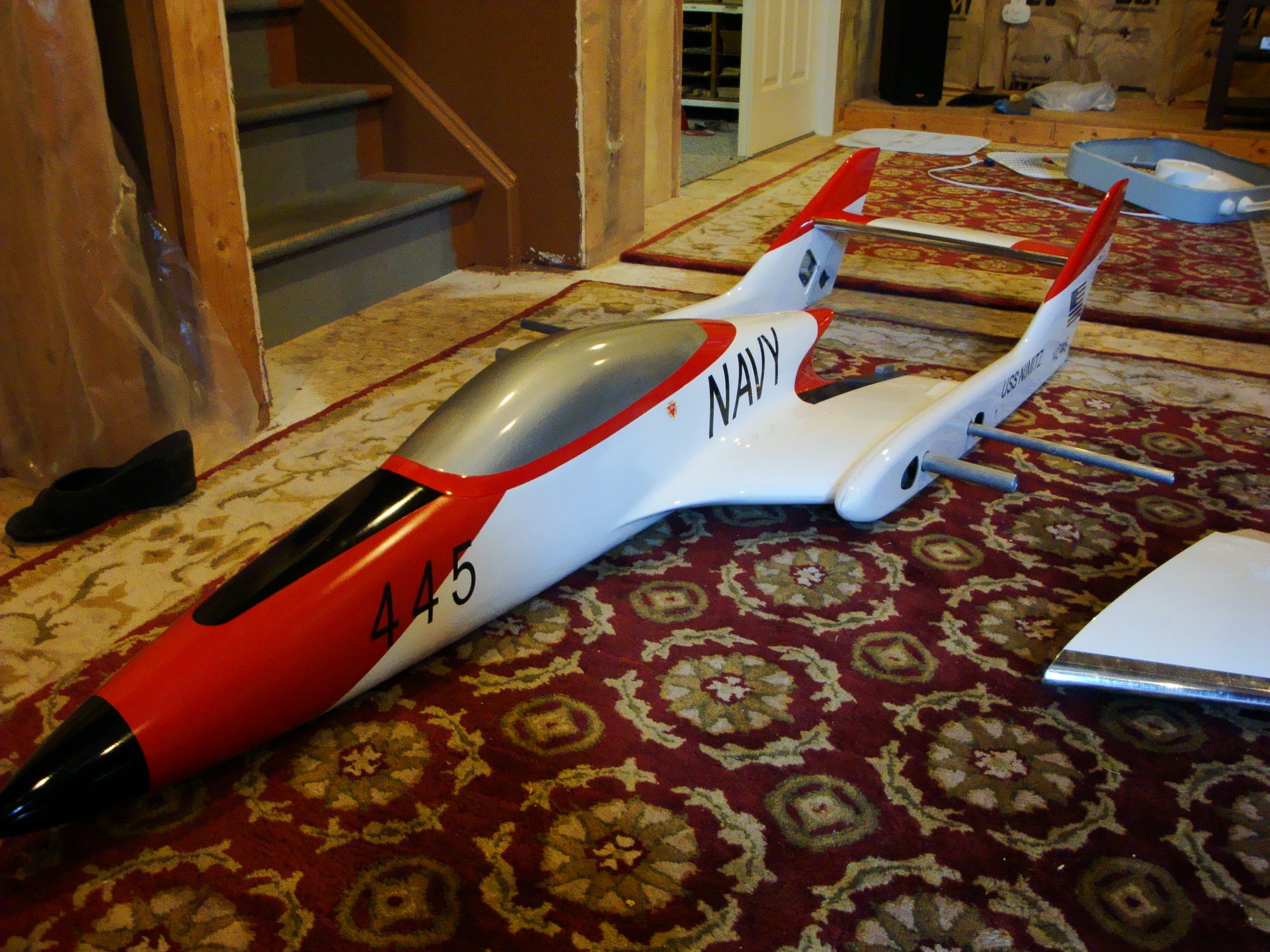
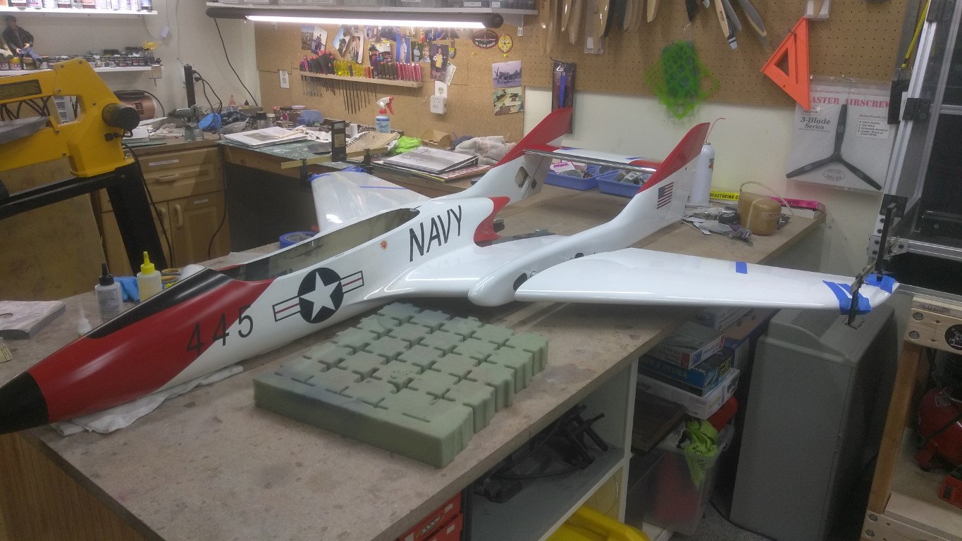
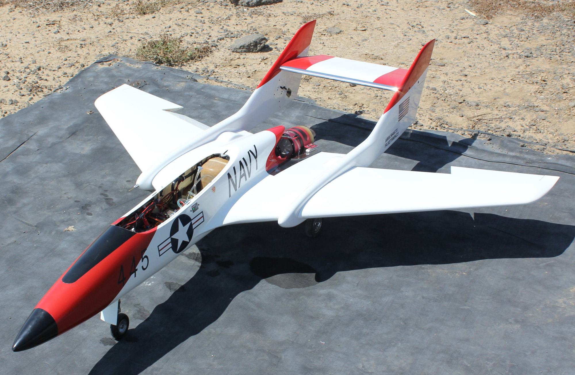
A wild ago I got this Bobcat composite with a broken nose. Since then I mostly restored it and started to install the refurbished gears.
Since I don't any reference as where the scribe lines for the front gear door are supposed to be, I would greatly appreciate if a bobcat composite owner could reply with the curved distance value from the nose tip to the edge of the nose wheel gear door opening.
Thank you,
Bruno
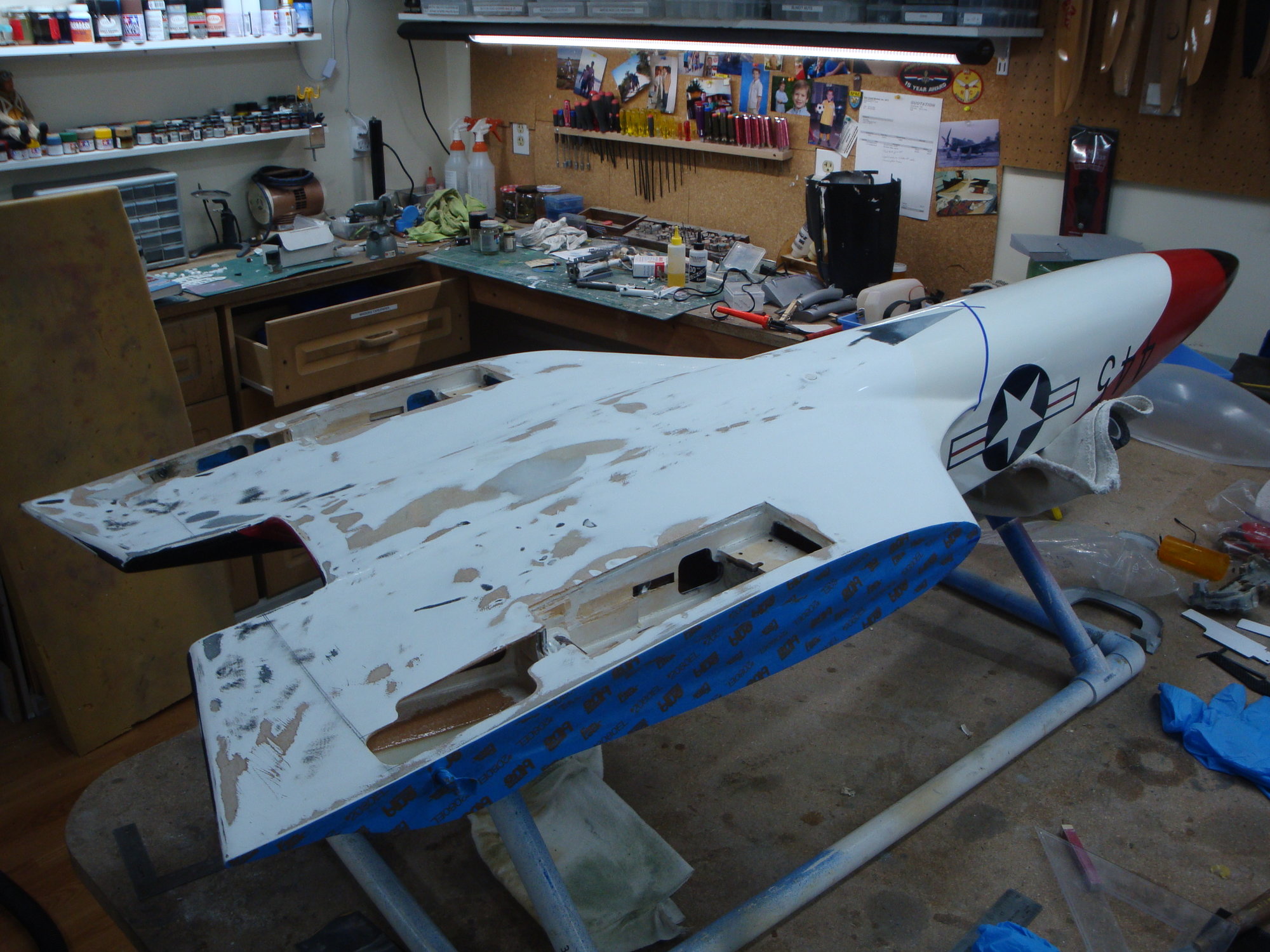
Since I don't any reference as where the scribe lines for the front gear door are supposed to be, I would greatly appreciate if a bobcat composite owner could reply with the curved distance value from the nose tip to the edge of the nose wheel gear door opening.
Thank you,
Bruno
 11-03-2019, 01:28 PM
#2
More work has been done since my last post.
BVM guys were kind enough to send me the cut out dimensions from the nose tip to the front gear door.
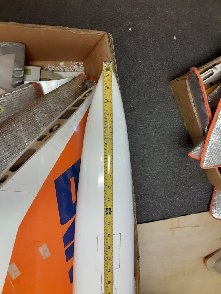
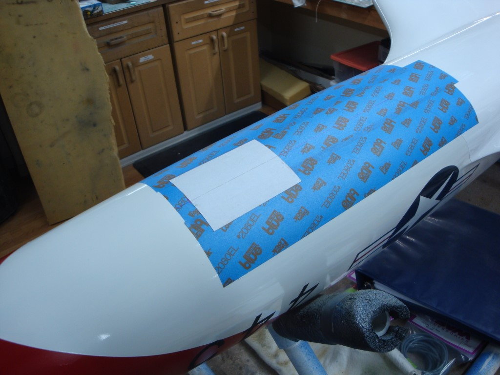
It allowed me to get the gear door cut-out at the proper location so to follow with installing the internal formers.
BVM guys were kind enough to send me the cut out dimensions from the nose tip to the front gear door.
It allowed me to get the gear door cut-out at the proper location so to follow with installing the internal formers.
11-03-2019, 01:43 PM
#3
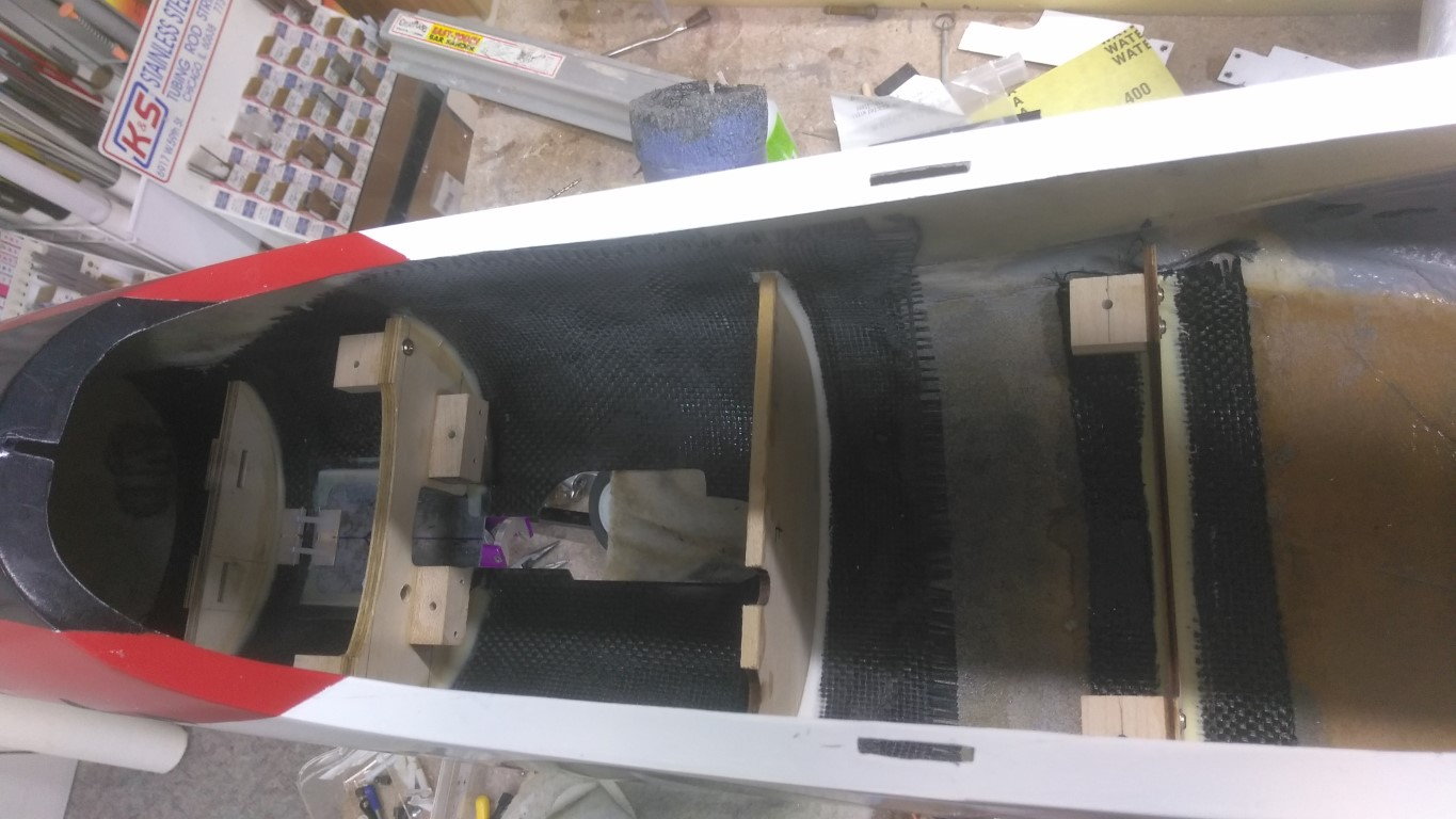
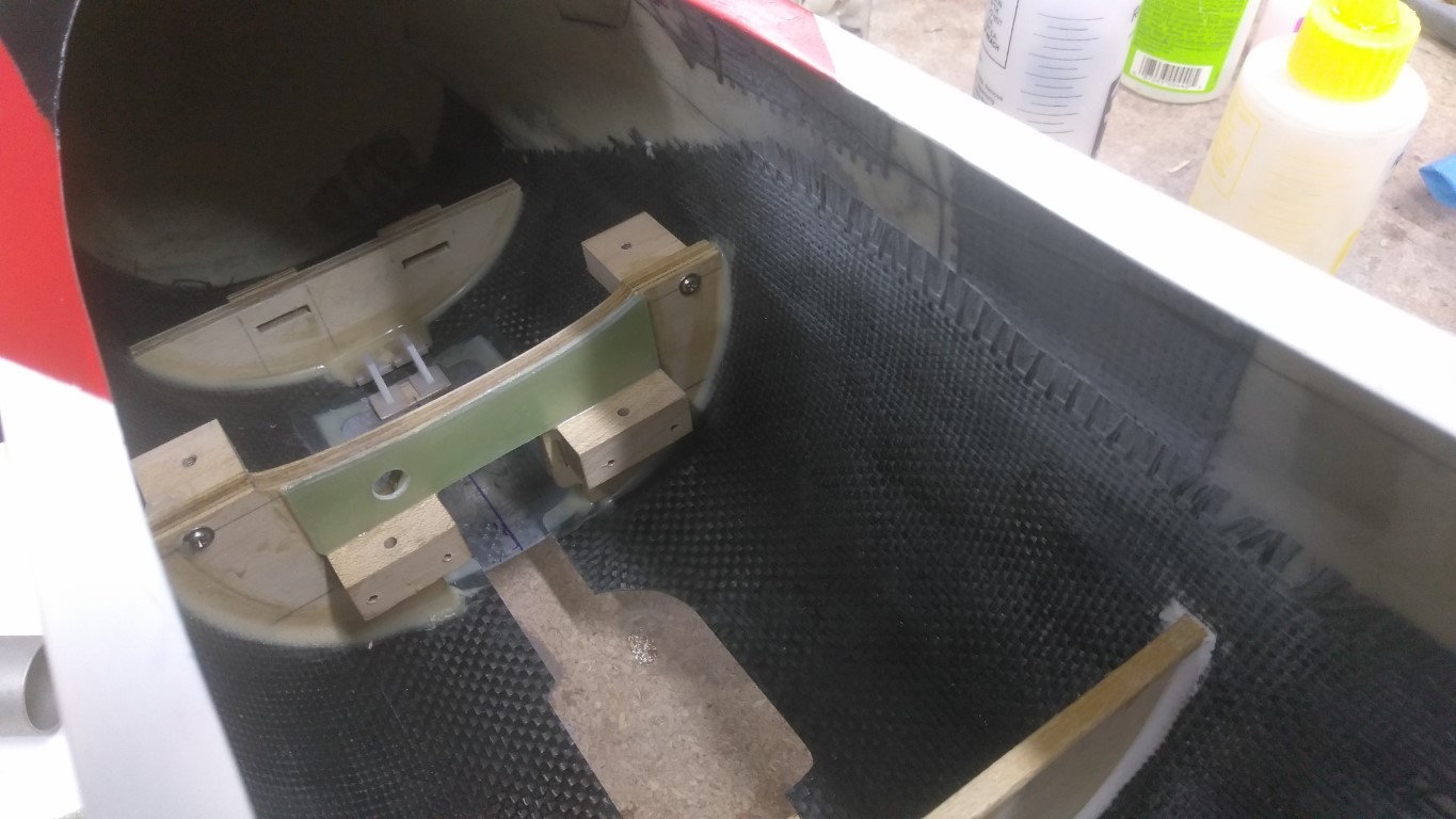
It probably doesn't need it but I went on and added a piece of G10 over the two nose landing gear plates mounting blocks.
I received my new set of wings mid October, the wrong phenolic tubes were provided and BVM was very kind the send me the correct ones. The trouble now is now about setting the proper incidence for the wings. Since when you buy a complete Bobcat kit, the plywood rings on the forward sleeve are setup in the factory to set the proper wing incidence. When you purchase replacement wings, those rings need to be installed, however there no info as what the wing incidence is in relation to the stab, for example. I just sent an email to BVM, hopping that they will be able to help, but if anyone has some information they could share, I would greatly appreciate!
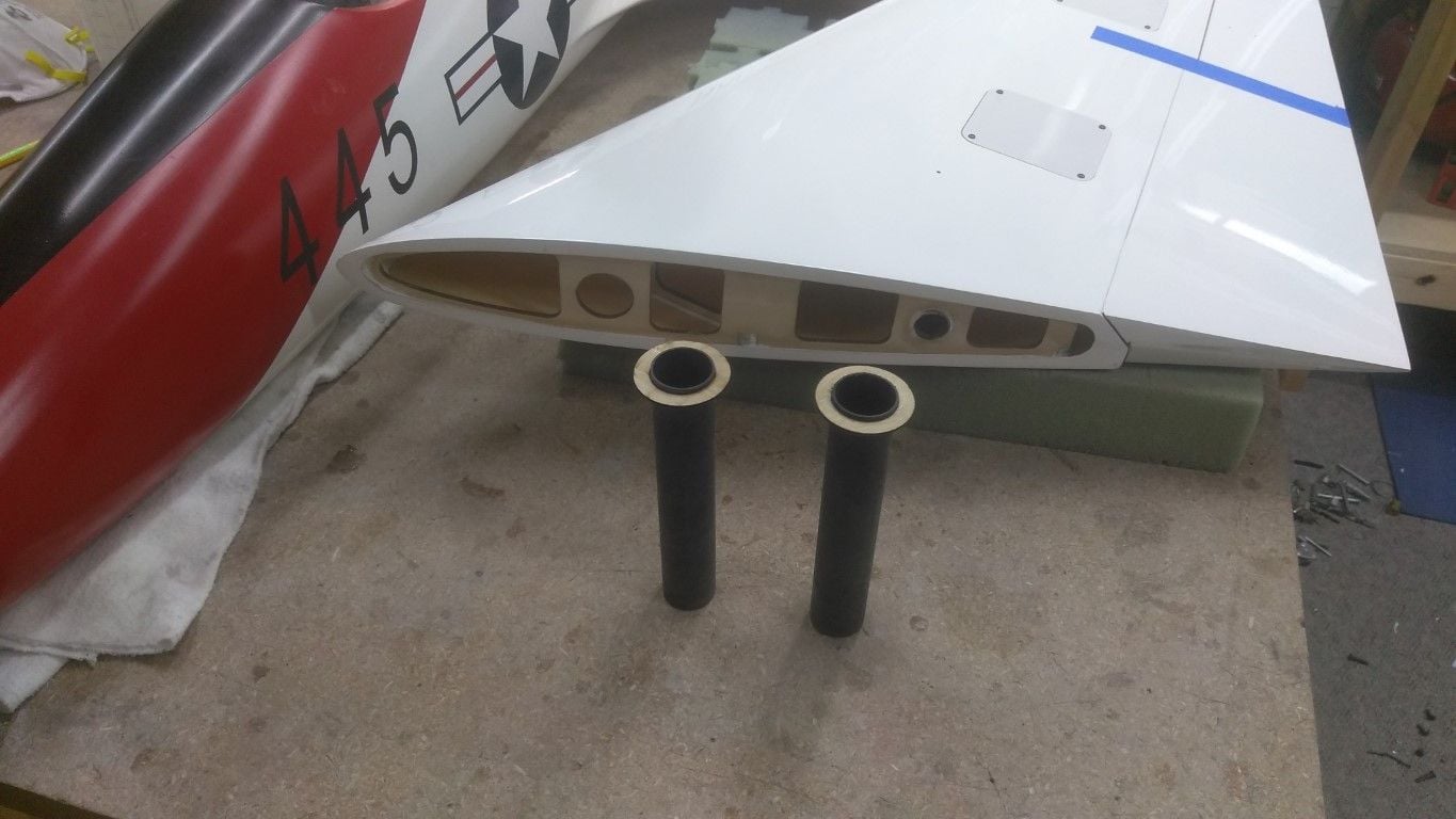
I received my new set of wings mid October, the wrong phenolic tubes were provided and BVM was very kind the send me the correct ones. The trouble now is now about setting the proper incidence for the wings. Since when you buy a complete Bobcat kit, the plywood rings on the forward sleeve are setup in the factory to set the proper wing incidence. When you purchase replacement wings, those rings need to be installed, however there no info as what the wing incidence is in relation to the stab, for example. I just sent an email to BVM, hopping that they will be able to help, but if anyone has some information they could share, I would greatly appreciate!
Last edited by flyingchef; 11-03-2019 at 01:47 PM.

 11-15-2019, 03:33 PM
#5
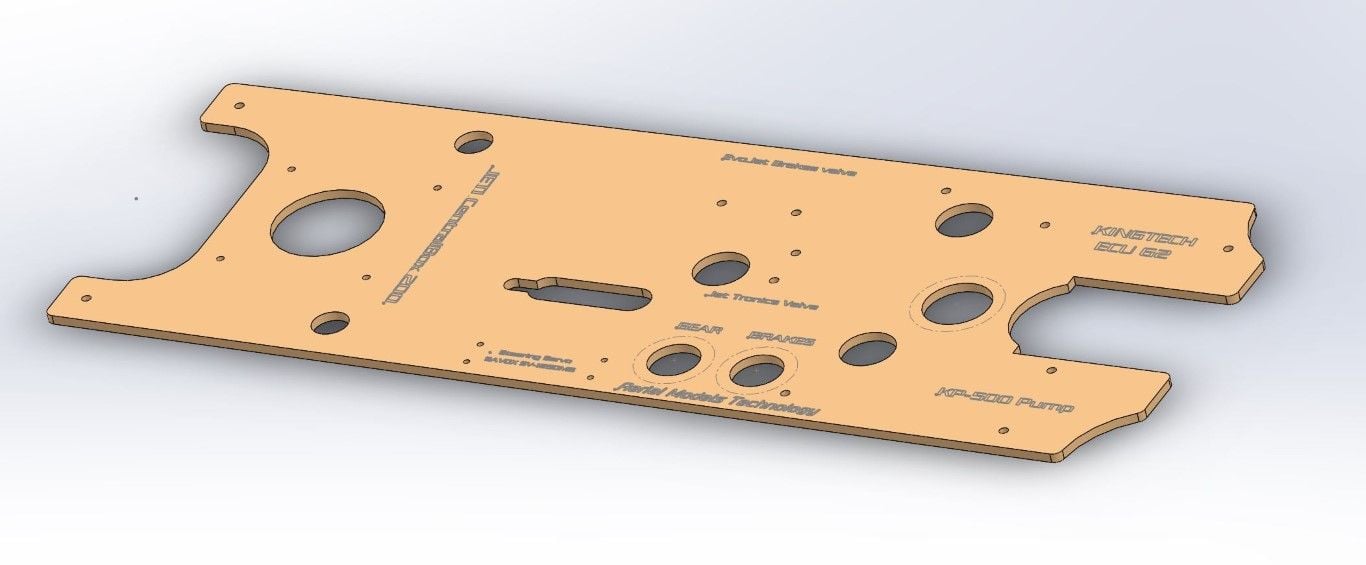
I am still waiting from BVM to get info on the wings incidence. Meanwhile, I laser cut the new electronics tray which I redesigned to fit the electronics and turbine equipment.
The second picture shows the original BVM tray on top, and the new one on the bottom
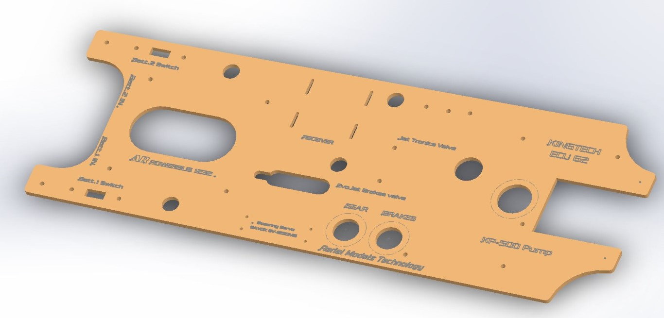
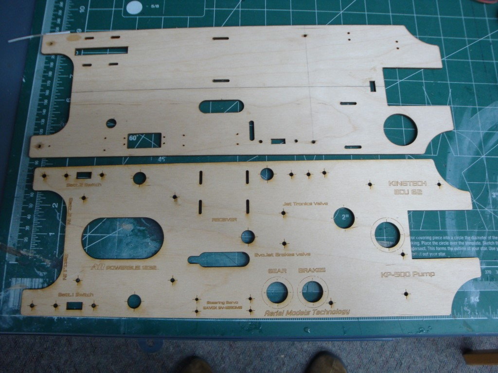
The second picture shows the original BVM tray on top, and the new one on the bottom
Last edited by flyingchef; 11-15-2019 at 03:35 PM.
 01-11-2020, 03:03 PM
#8
I have been working on the jet and taking a moment to post some updates. Thank you also to yeahbaby and Ravill for the support.
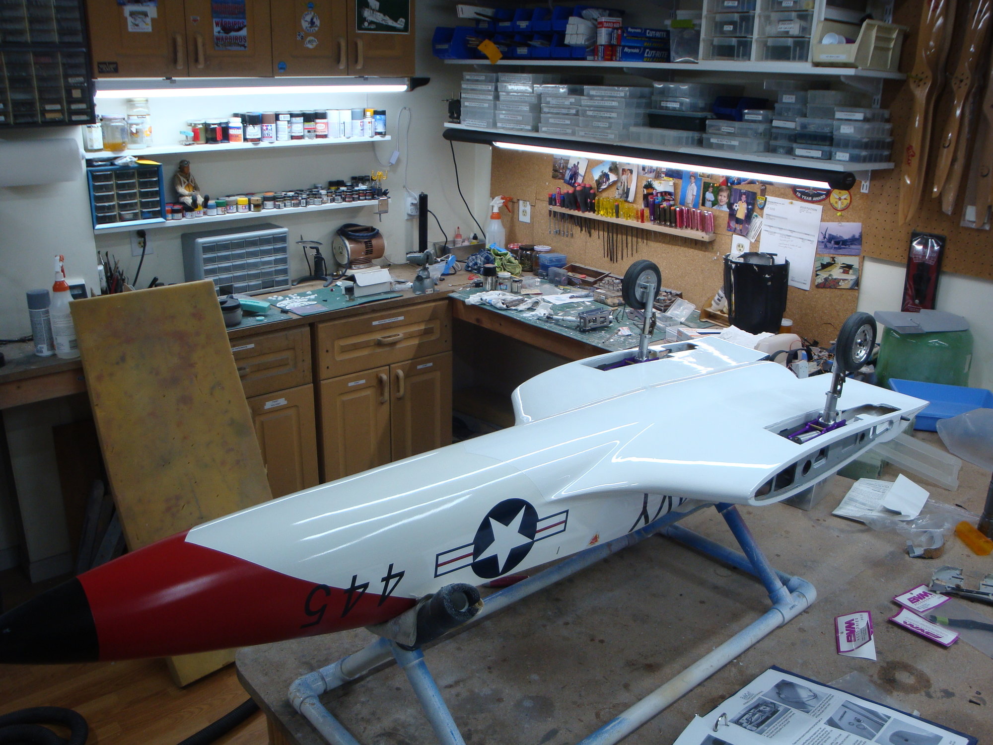
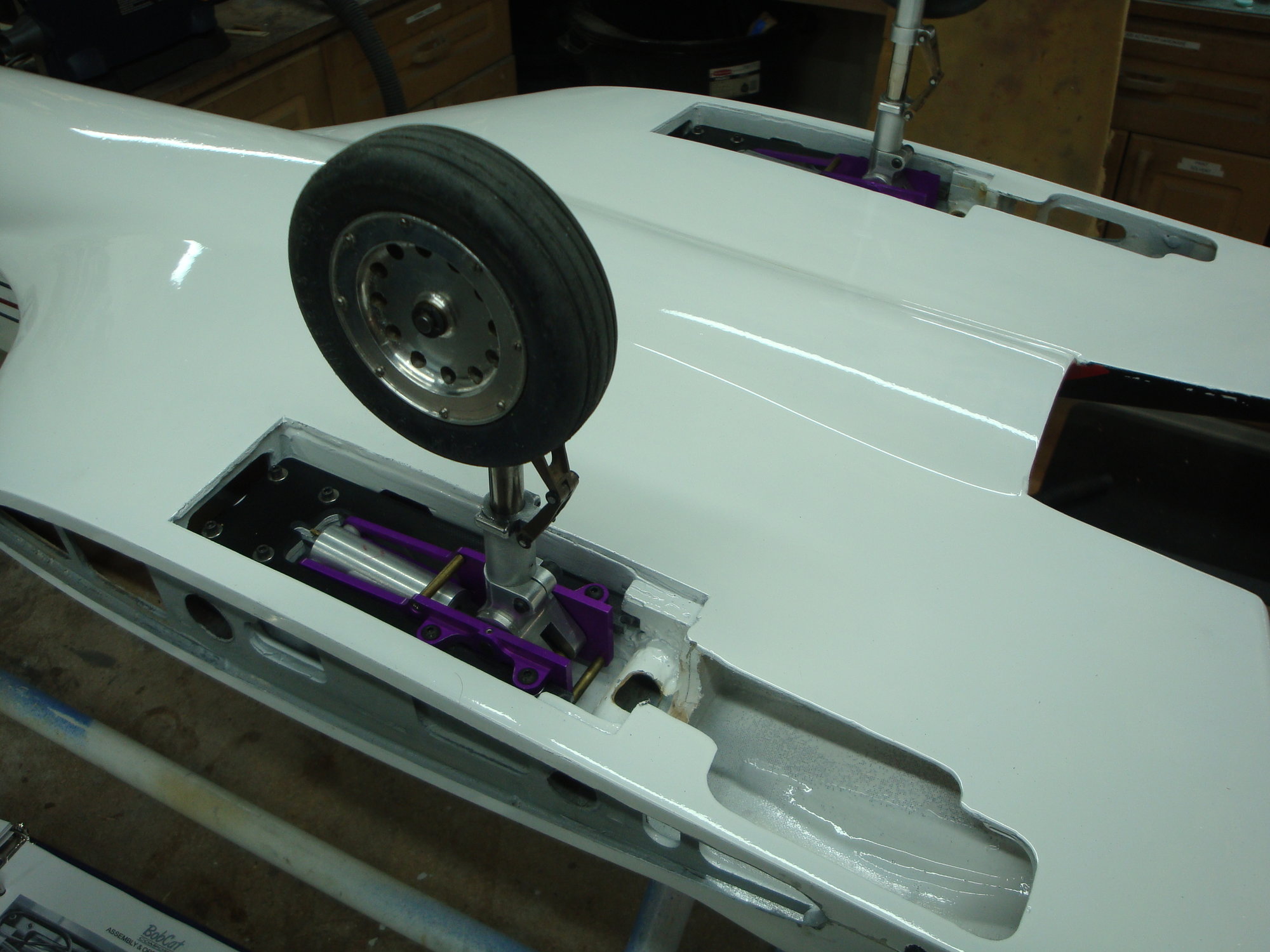
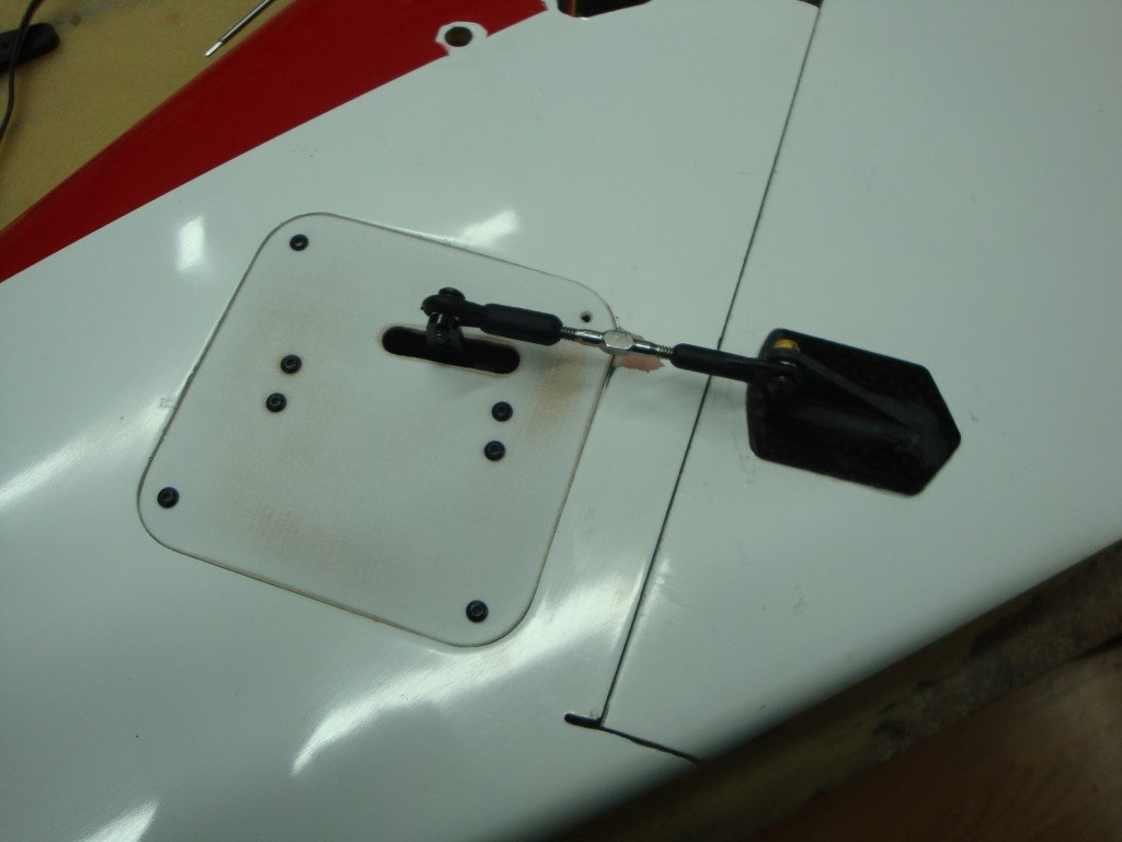
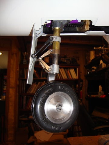
The nose gear and gear are done. I was not a fan of the "floating" gear door so I went the hard way and hinged it on the strut. The strut rotate in the door mount and the brass sleeves.
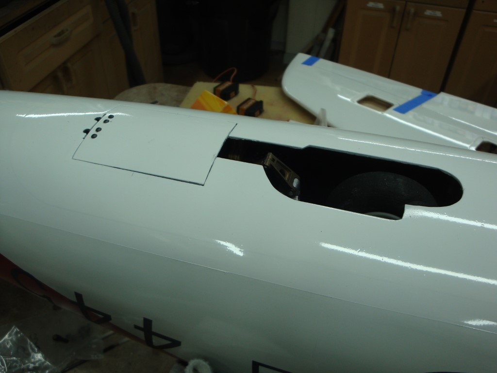
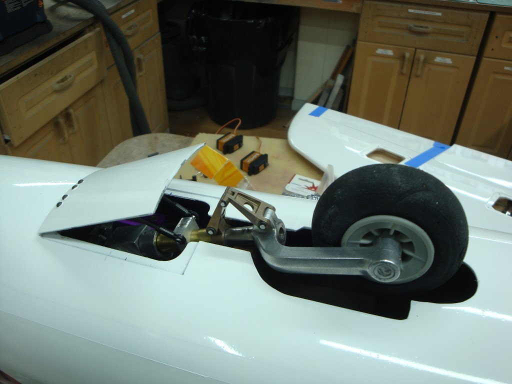
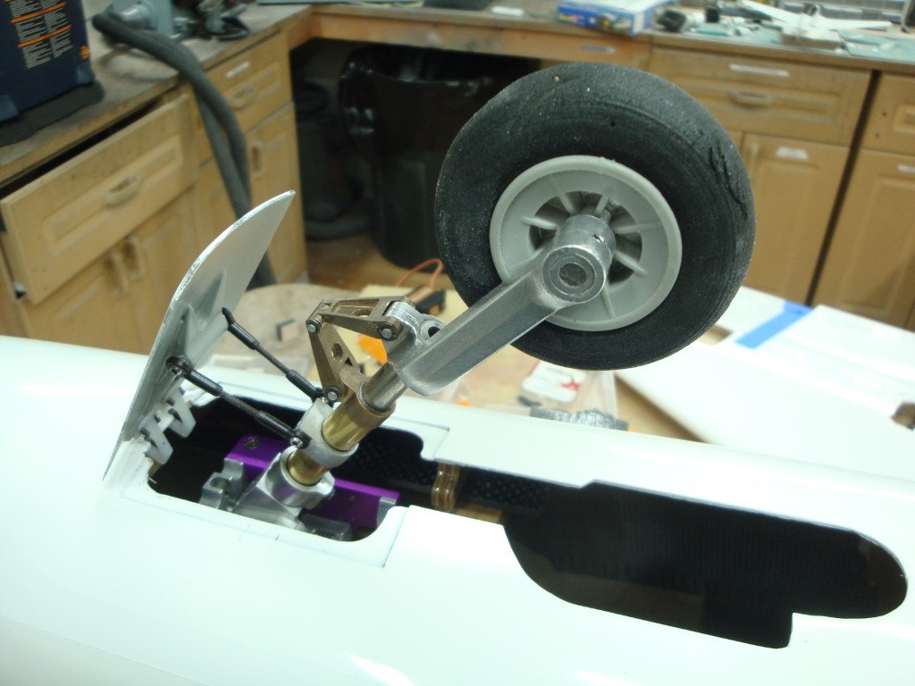
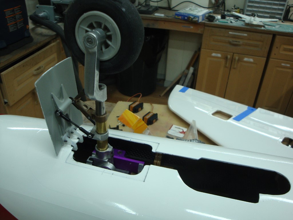
The nose gear and gear are done. I was not a fan of the "floating" gear door so I went the hard way and hinged it on the strut. The strut rotate in the door mount and the brass sleeves.
01-11-2020, 04:04 PM
#9
For servos, I installed Savox SV-1270TG on elevator, flaps, and ailerons. As for the rudders, BVM recommended couple SV-1260MG.
I deviated from the manual for the rudder servos installation. Instead, I made a 3D printed mount. The servo slides inside and is locked with the hatch.
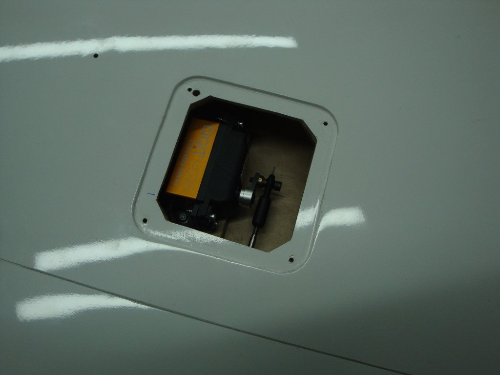
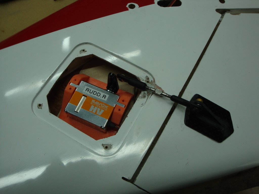
I deviated from the manual for the rudder servos installation. Instead, I made a 3D printed mount. The servo slides inside and is locked with the hatch.
01-12-2020, 04:55 PM
#10
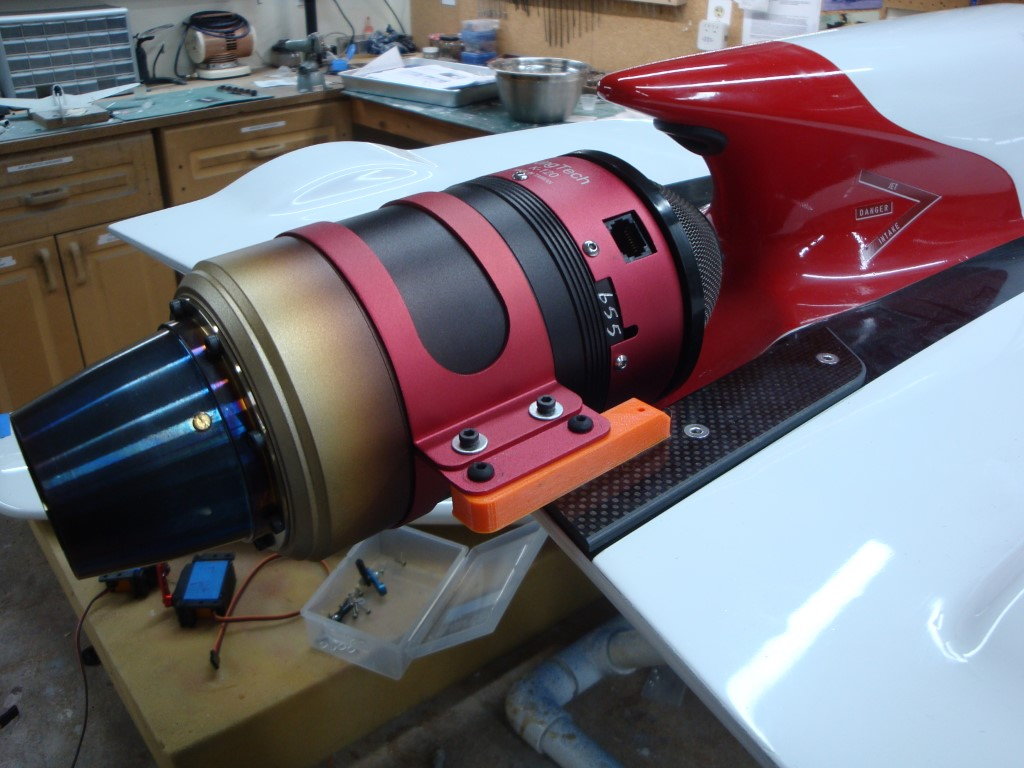
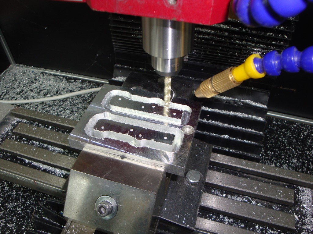
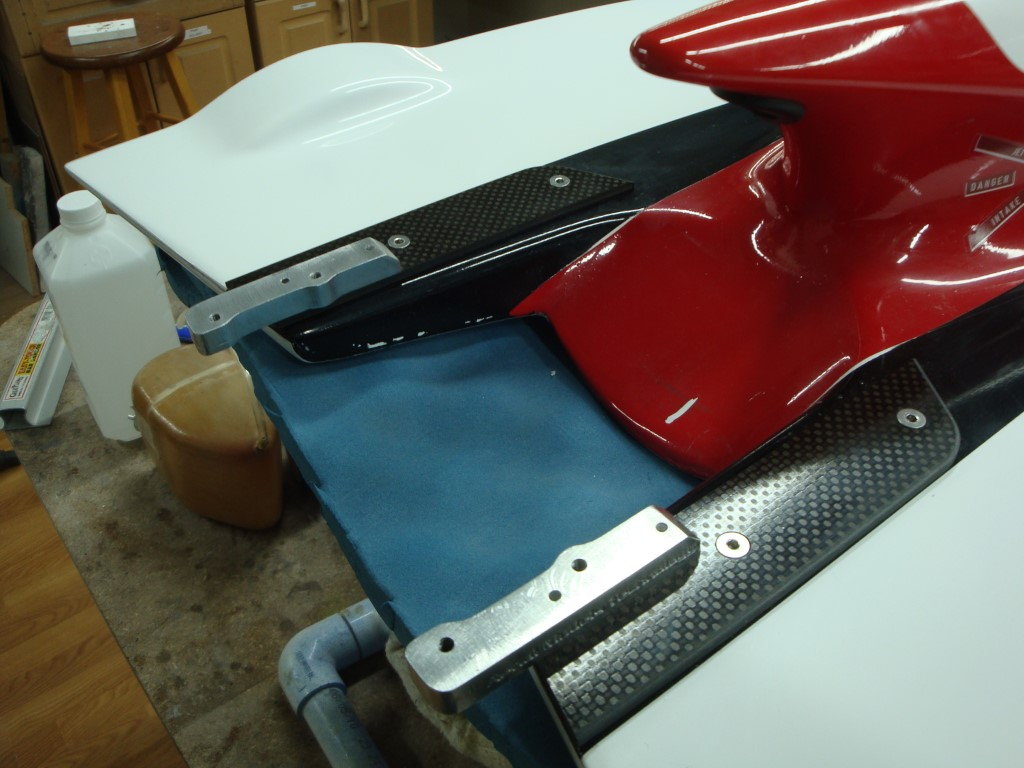
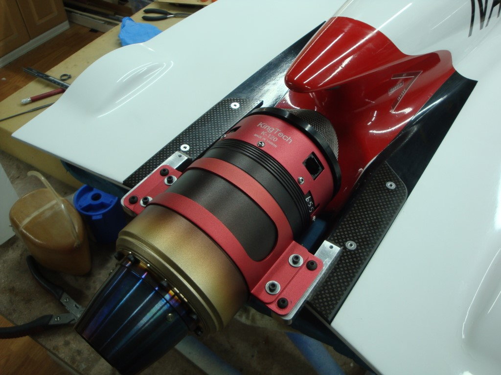
Designed new turbine mounts then verified the fitting with 3D printed version. I will be machining the final version next weekend.
Original mounts
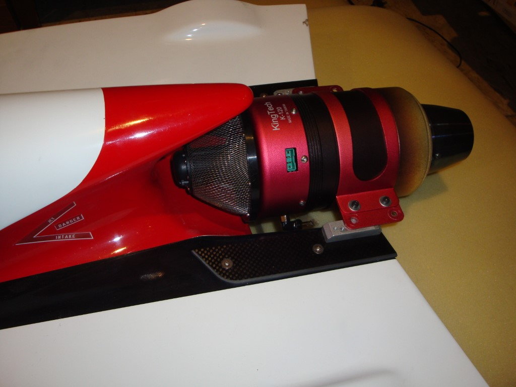
First prototype: In the manual the noted distance between the turbine bracket holes is 136 mm, in reality I measured 140 mm
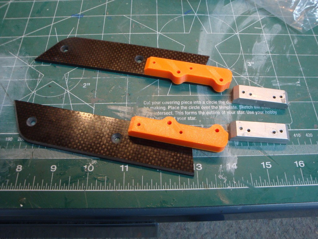
Version with 140 mm hole to hole.
Original mounts
First prototype: In the manual the noted distance between the turbine bracket holes is 136 mm, in reality I measured 140 mm
Version with 140 mm hole to hole.
Last edited by flyingchef; 01-12-2020 at 04:57 PM.
 01-18-2020, 01:12 PM
#13
Ravill,
I would not dare putting a 140 on a Bobcat, I have the 120 and will tune it down to 130,000. I also fly at 5280 Ft which reduce the thrust by ~20%
I Have a table top mill from Harbor Freight which I converted to CNC. My lathe is also from HF, it originally a 7X10 but installed the 16" bed.
Sirrom,
I designed the tray in SolidWorks, and Adobe Illustrator for laser cutting.
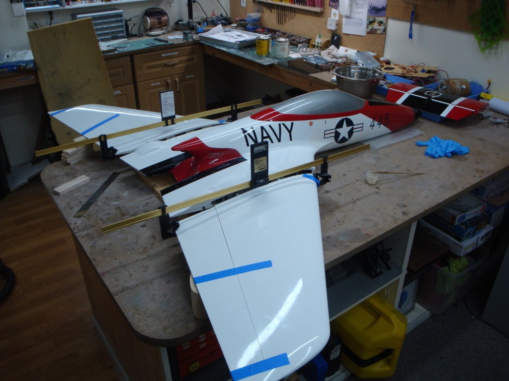
Glued the wing tubes today with Aeropoxy, I have also installed the flaps and ailerons servos.
I would not dare putting a 140 on a Bobcat, I have the 120 and will tune it down to 130,000. I also fly at 5280 Ft which reduce the thrust by ~20%
I Have a table top mill from Harbor Freight which I converted to CNC. My lathe is also from HF, it originally a 7X10 but installed the 16" bed.
Sirrom,
I designed the tray in SolidWorks, and Adobe Illustrator for laser cutting.
Glued the wing tubes today with Aeropoxy, I have also installed the flaps and ailerons servos.
 03-29-2020, 12:11 PM
#17
A bit off progress has been achieved since my last post in February.
All the servos have been installed and I upgraded my radio to a new Jeti DS12.
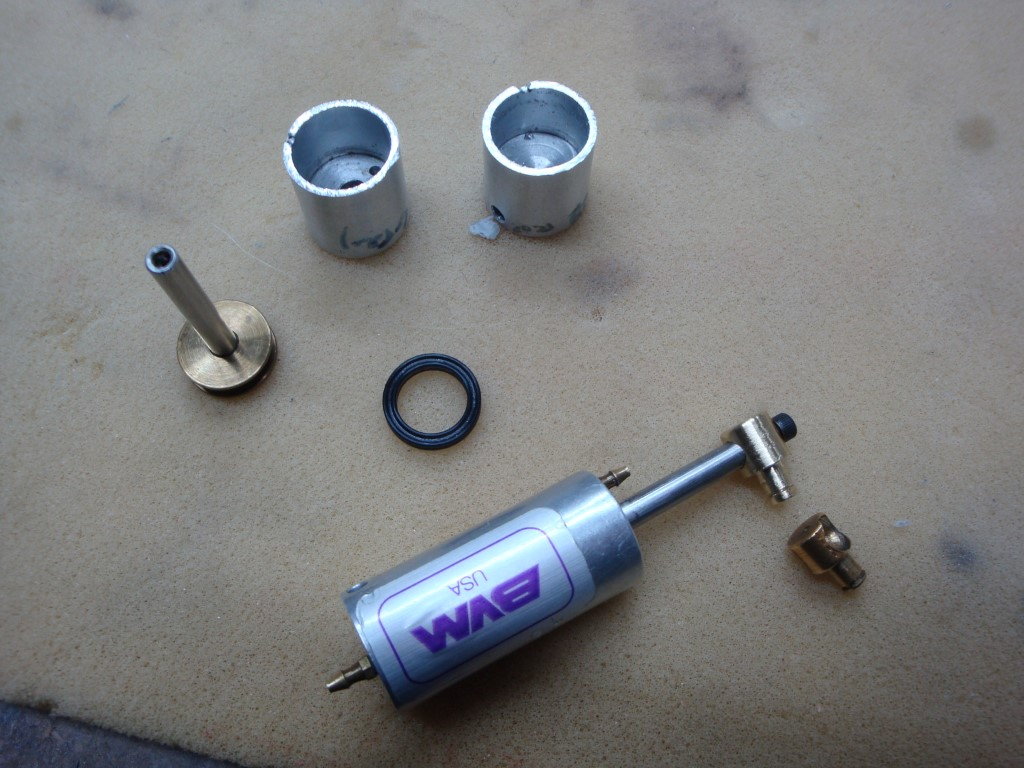
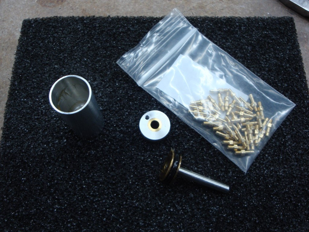
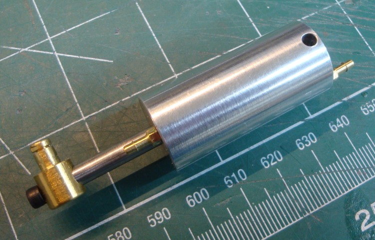
I received the new nose gear retract cylinder and machining a new one at the same time. I found a source for the 1/16", 3-56 thread, fittings and now in the process to finish assembling the new machined cylinder.
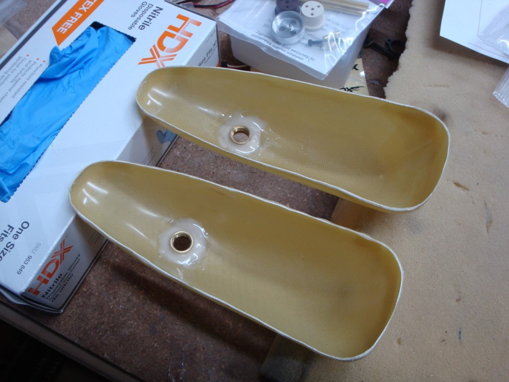
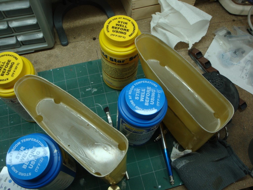
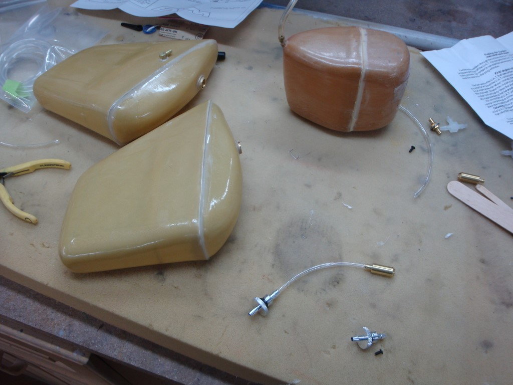
The new set of Kevlar fuel cells are glued and I moving forward with cutting a brace that will hold all three cells in place. I'd like to cut it using the same foam type that rc helicopters blades holder are made off, I just can't find the particular name of the foam material so to buy a sheet/block.
If you happen to know the technical name, please share it!
All the servos have been installed and I upgraded my radio to a new Jeti DS12.
I received the new nose gear retract cylinder and machining a new one at the same time. I found a source for the 1/16", 3-56 thread, fittings and now in the process to finish assembling the new machined cylinder.
The new set of Kevlar fuel cells are glued and I moving forward with cutting a brace that will hold all three cells in place. I'd like to cut it using the same foam type that rc helicopters blades holder are made off, I just can't find the particular name of the foam material so to buy a sheet/block.
If you happen to know the technical name, please share it!

 05-06-2020, 04:09 PM
#23
Thanks Henry,
Did not post for while, just been busy with airplane projects. I finished the nose wheel hub last week, mounted and ready to go. Since my last post, I switched to a Jeti DS-12 system. I designed a new electronics tray layout (3rd one) and finishing the installation (Central Box 200, and couple R3 receivers). I also added the expansion switch board in the DS-12 with a throttle momentary button, swapped some other switches around, and added a locking 2 position.
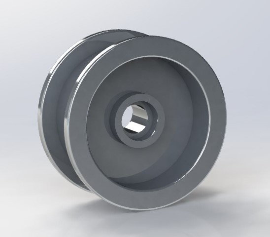
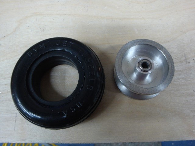
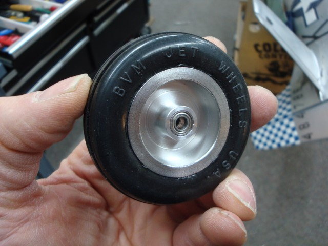
Did not post for while, just been busy with airplane projects. I finished the nose wheel hub last week, mounted and ready to go. Since my last post, I switched to a Jeti DS-12 system. I designed a new electronics tray layout (3rd one) and finishing the installation (Central Box 200, and couple R3 receivers). I also added the expansion switch board in the DS-12 with a throttle momentary button, swapped some other switches around, and added a locking 2 position.
Last edited by flyingchef; 05-06-2020 at 04:13 PM.
05-30-2020, 02:27 PM
#24
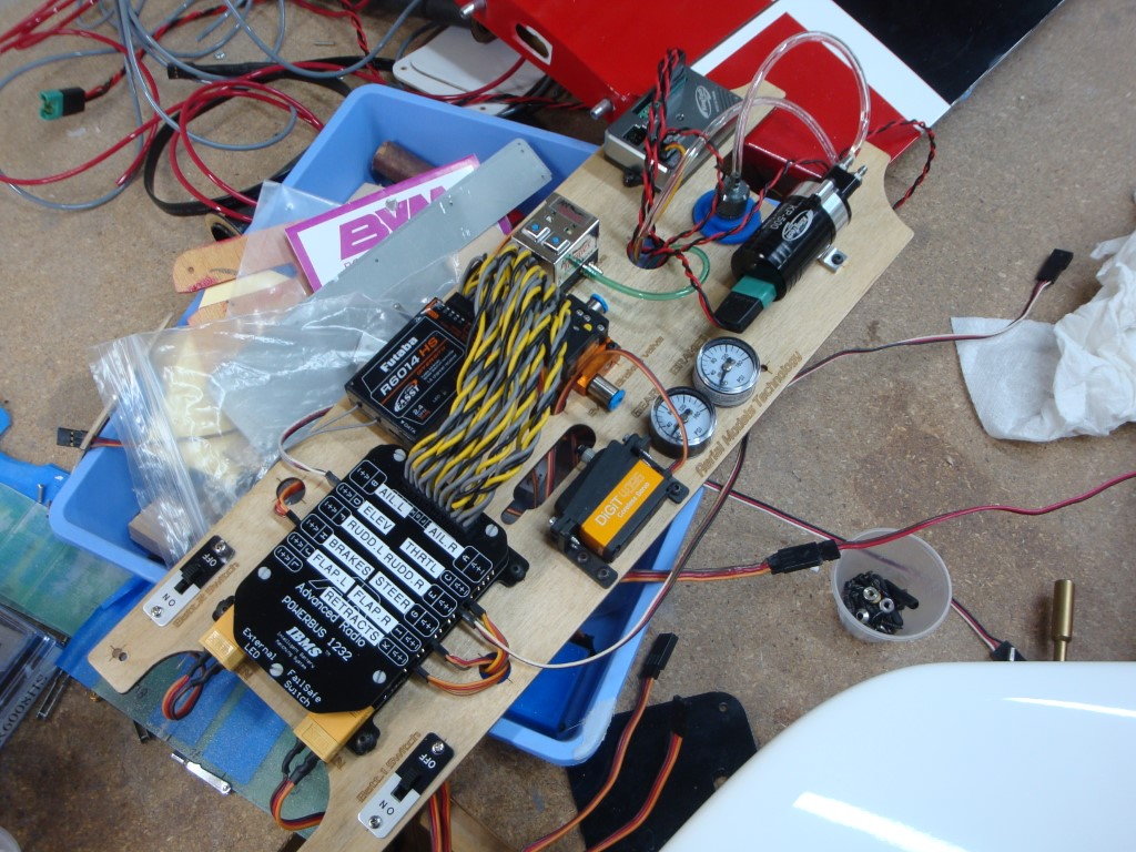
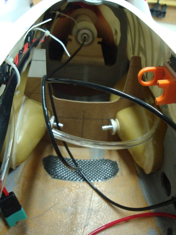
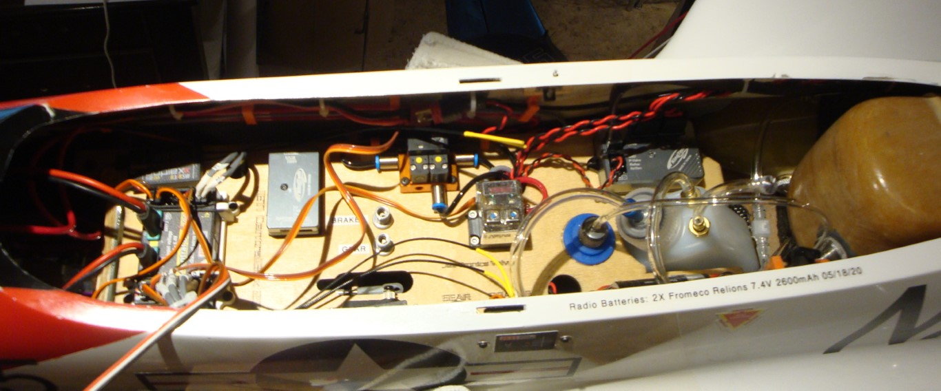
Since my last post, I finished all the electronics installation. Since I switched to the Jeti DS12, I cut a third electronics tray layout to reconfigure the installation.
The setup consist now of the Central Box 200 and two R3 receivers. I also slightly modified the UAT tank sitting.
Still in the process of completing the setup.
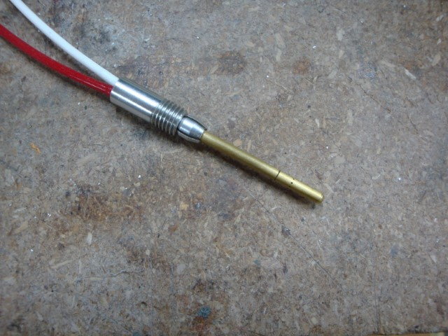
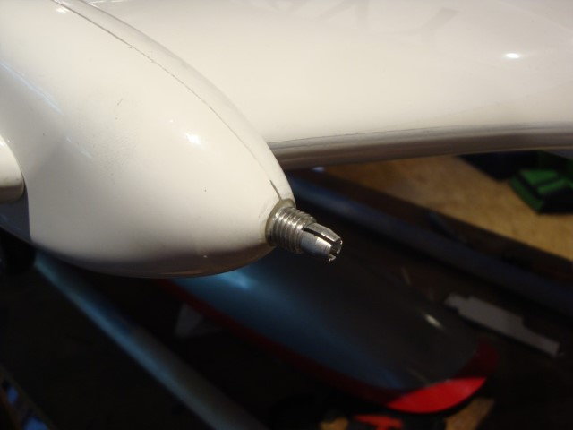
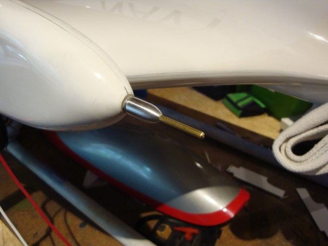
Next is to setup the airspeed sensor. I machined a small unit that uses a Dremel 1/8" aluminum collet. All seems to hold pretty well once the cap is on.
The setup consist now of the Central Box 200 and two R3 receivers. I also slightly modified the UAT tank sitting.
Still in the process of completing the setup.
Next is to setup the airspeed sensor. I machined a small unit that uses a Dremel 1/8" aluminum collet. All seems to hold pretty well once the cap is on.
Last edited by flyingchef; 05-31-2020 at 05:10 AM.
The following users liked this post:
makis (08-18-2020)