


125% (1/4 scale) Anderson TA-152H


 12-05-2014, 06:51 PM
#102


So Invert, you are going to offer this as a kit, or just the fuselage, and possibly the more scale retracts? How about the wing? Will that need to be blown up and scratch built to plans per the interested party? I guess I do not understand exactly what is going on with this build now! lol
Well, maybe it will be a little easier being bigger, but I love building wings, and this one was by far the most difficult thing I have ever encountered. IMO, it really needs a trailing edge, added in front of the flaps. Just like a conventional wing build. It would just help to ensure that it stays straight. I drew a centerline on all of my ribs at the LE and then also on the leading edge stock to avoid twist.
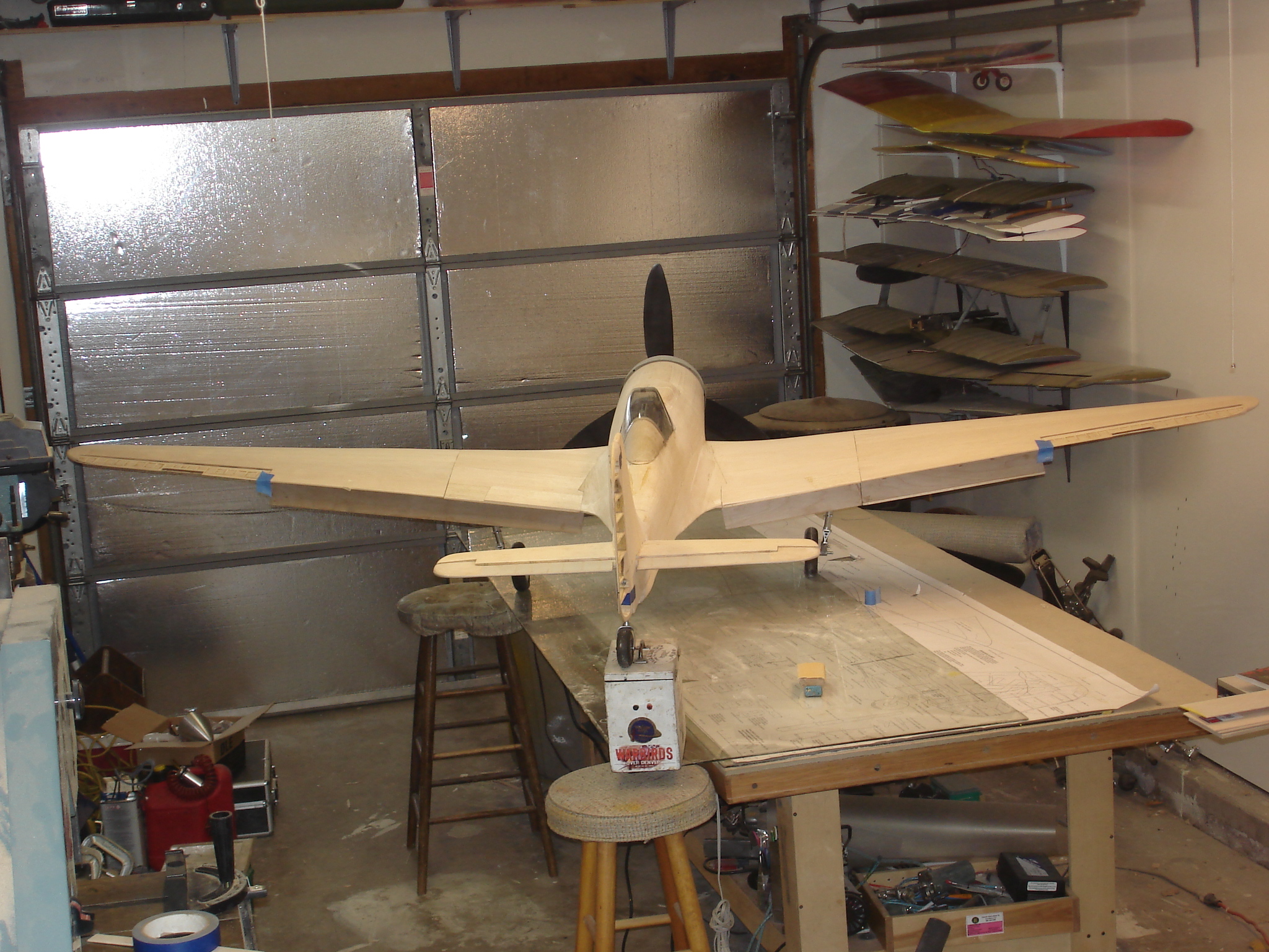
I threw the incidence meter on last week, and I have exactly 2 degrees washout. So I am happy with how straight mine is, but it was a chore, and care must be taken.
Well, maybe it will be a little easier being bigger, but I love building wings, and this one was by far the most difficult thing I have ever encountered. IMO, it really needs a trailing edge, added in front of the flaps. Just like a conventional wing build. It would just help to ensure that it stays straight. I drew a centerline on all of my ribs at the LE and then also on the leading edge stock to avoid twist.
I threw the incidence meter on last week, and I have exactly 2 degrees washout. So I am happy with how straight mine is, but it was a chore, and care must be taken.
Man yours looks great!
As far as where I am going, ive got four fuselages sold already, so the fuselage, cowl, gunhood, belly pan, and canopy frame is all getting molded so i can do glass fuselages. The plans are then able to be enlarged 125% so the builder can do his own built up wings/tail. I also have cut files for wing and tail parts to ease life a little easier. I also plan to design a set if balsa/ply control surfaces so as to eliminate alot of the weight and carving required with the plans built way of building them.
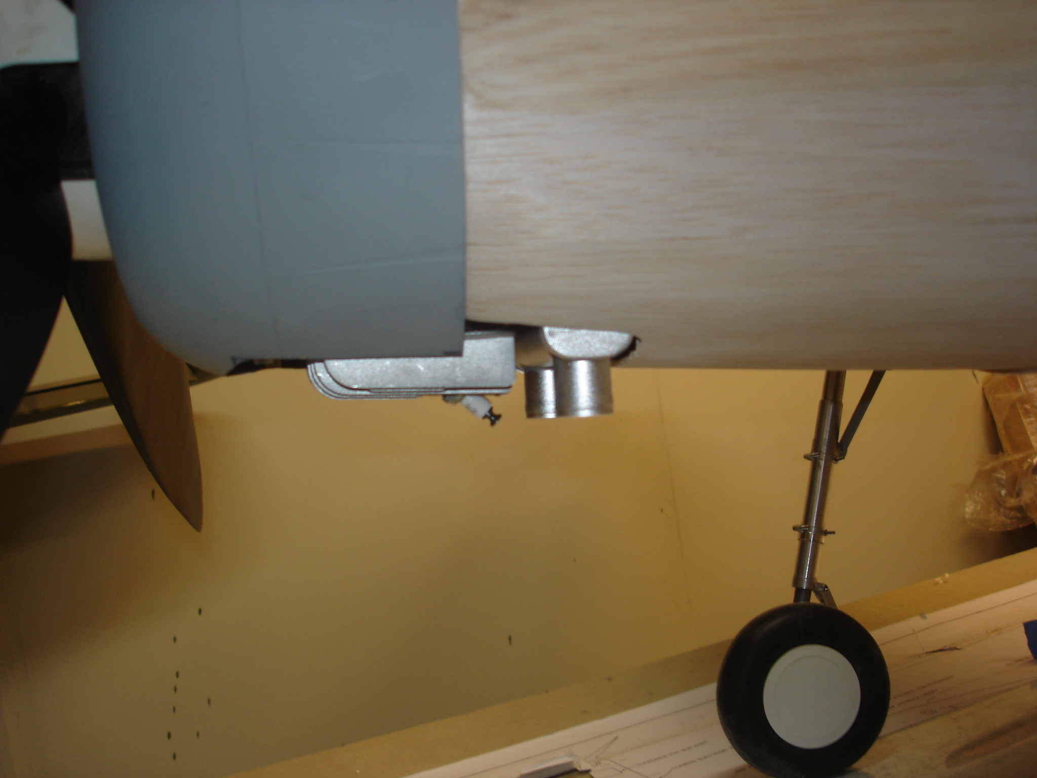
the super accurate scale landing gear will also be available as well. Eventually i want to offer them in 1/5 scale and in FW-190 variants (there are some subtle, yet significant difference between the two).
That is plan A.
Plan B is an all composite airframe kit. This wont happen unless i get a minimum of 5 people to put up a fairly substantial non refundable deposit. The reason im requiring the deposit is to weed out the "I'll take one for sure" groupies who never actually buy one.
12-05-2014, 07:15 PM
#103
Thanks Invert. As you know, it is a lot of work!
That is great that you are doing this. It might be of benefit to the prospective builders of yours, to be able to use the same laser cutter, so you know they can trust them, and get accurate parts. Also, the cutter will already have the program made. PCK, really had me pulling my hair out on this one. Especially on the wing. Good accurate parts make all the difference in the world.
That is great that you are doing this. It might be of benefit to the prospective builders of yours, to be able to use the same laser cutter, so you know they can trust them, and get accurate parts. Also, the cutter will already have the program made. PCK, really had me pulling my hair out on this one. Especially on the wing. Good accurate parts make all the difference in the world.
12-05-2014, 07:24 PM
#104
Thanks Invert. As you know, it is a lot of work!
That is great that you are doing this. It might be of benefit to the prospective builders of yours, to be able to use the same laser cutter, so you know they can trust them, and get accurate parts. Also, the cutter will already have the program made. PCK, really had me pulling my hair out on this one. Especially on the wing. Good accurate parts make all the difference in the world.
That is great that you are doing this. It might be of benefit to the prospective builders of yours, to be able to use the same laser cutter, so you know they can trust them, and get accurate parts. Also, the cutter will already have the program made. PCK, really had me pulling my hair out on this one. Especially on the wing. Good accurate parts make all the difference in the world.
that is the plan.
Its hard to tell, but does your wing have the kink in the trailing edge?
12-05-2014, 07:30 PM
#105
It actually does. It is more of a bow, which kinda blows the fit of the flat flap that I laminated. The kink is scale, and I think that is what makes building the wing so tricky. In all honesty, I wish it were not designed into the structure, as it is truly something nobody would ever see. Even in scale competition, I do not have a 3 view that shows it, as it is something you notice more from the aft view. So, any judges seeing my docs, will not see it.
Oh, scale competition is a tricky beast. It is one thing to build a perfectly scale model, and another to build a competition scale model. They are 2 different things. Despite what many believe. By the way, mine is for competition.
Oh, scale competition is a tricky beast. It is one thing to build a perfectly scale model, and another to build a competition scale model. They are 2 different things. Despite what many believe. By the way, mine is for competition.
12-05-2014, 08:02 PM
#106
It actually does. It is more of a bow, which kinda blows the fit of the flat flap that I laminated. The kink is scale, and I think that is what makes building the wing so tricky. In all honesty, I wish it were not designed into the structure, as it is truly something nobody would ever see. Even in scale competition, I do not have a 3 view that shows it, as it is something you notice more from the aft view. So, any judges seeing my docs, will not see it.
Oh, scale competition is a tricky beast. It is one thing to build a perfectly scale model, and another to build a competition scale model. They are 2 different things. Despite what many believe. By the way, mine is for competition.
Oh, scale competition is a tricky beast. It is one thing to build a perfectly scale model, and another to build a competition scale model. They are 2 different things. Despite what many believe. By the way, mine is for competition.
Yea i hear ya. Im planning atleast one competition model with mine, i may end up doing two for myself.
You mentioned earlier about needing a read spar at the flap LE, that is one thing I plan to do as i plan to use some thin ply and a fairly well detailed flap well.
12-05-2014, 08:08 PM
#107
On the wing T.E., If it were me, I would cut all of the little "points" that create the sharp T.E., and add them later, after the leading edge of the flap (i will call it) is added. I am pretty sure Jose of Fliteskin did this, and I know the wing of the other 1/4 scale TA 152 that went on in here for a couple of years did as well.
12-05-2014, 08:22 PM
#109
That trailing edge structure on the 190 wing is a tricky beast. The most important thing is to create a structure that is engineered to be easily built straight. The scale aspect of the half ribs and such of the flap section, can be dealt with after the fact, then sheeted over. The TA 152 makes it even worse as it is so long. I am sure you will have no trouble with your experience. Yours is going to be a great addition to the few options we have for this design.
12-05-2014, 08:30 PM
#110
That trailing edge structure on the 190 wing is a tricky beast. The most important thing is to create a structure that is engineered to be easily built straight. The scale aspect of the half ribs and such of the flap section, can be dealt with after the fact, then sheeted over. The TA 152 makes it even worse as it is so long. I am sure you will have no trouble with your experience. Yours is going to be a great addition to the few options we have for this design.
12-05-2014, 09:10 PM
#115
I have to say that I cannot wait to fly this thing. I have built and flown at least 10 of these for 1/12th scale 2610 combat, back in the day. Even at that small scale, the design has a great feel about it. It is truly a pattern design, and to have it in such a large size, should prove to be wonderful.
My experience with flying these, is exactly the reason I wanted it for scale competition. Not only am I fascinated with the full scale, I know it can be a winner. As we all need all the help we can get! I am sure it will land slow, with all of that flap. Dave himself told me he has actually thermaled his at idle!
I had a great conversation at the Nats this year as well. I was told, not to get too caught up in how you do,or how your scores come out, as they will vary greatly from one event to the other. He told me to build what you are excited about and have fun. That is exactly what I am doing with the TA 152. It is one of my dream planes, in a large scale.
12-07-2014, 05:49 PM
#116
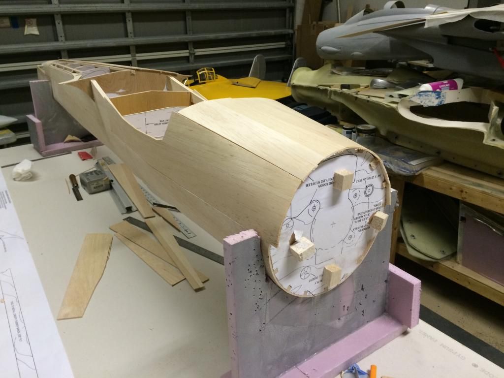
Today and i mean ALL day, was devoted to gun hood carving.
First up was a few filled pieces to level the top blocks and to get the bottom portion shaped.
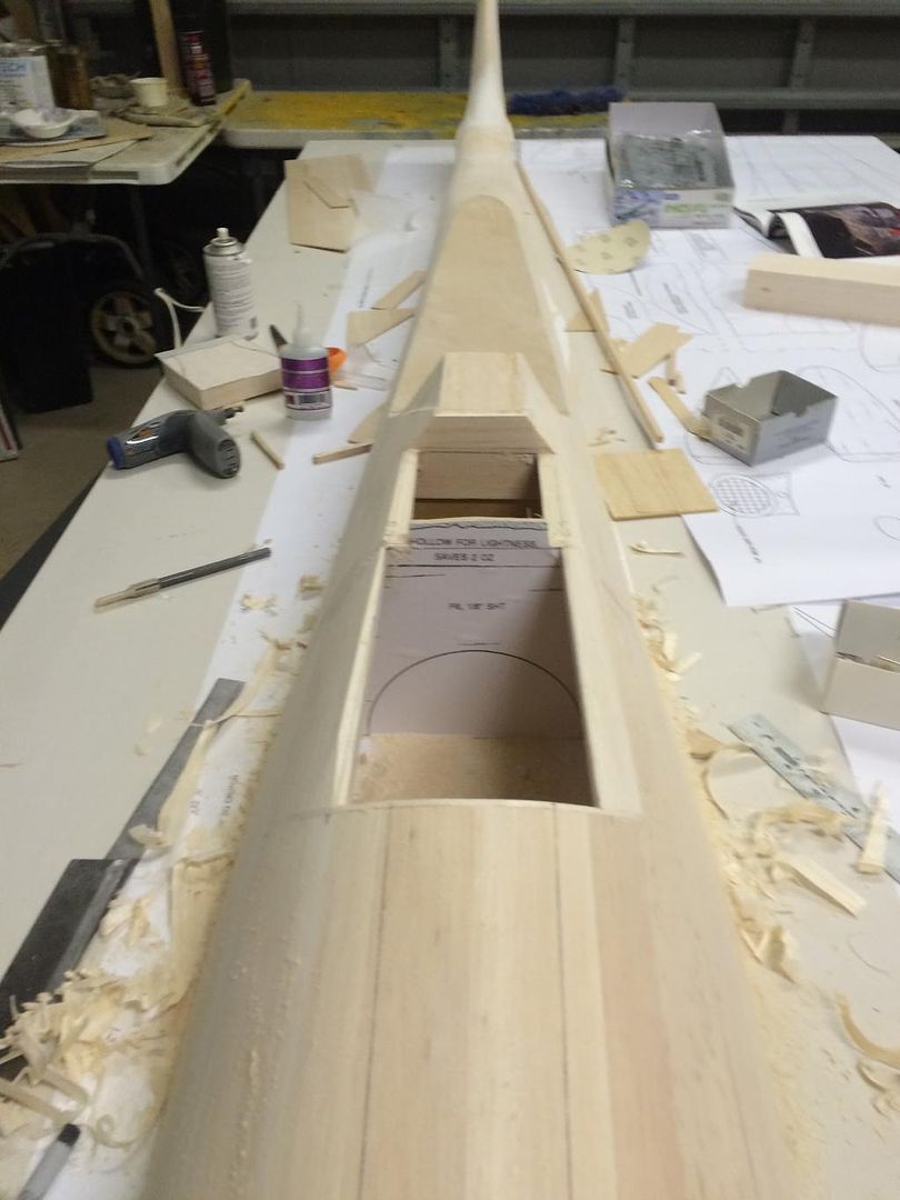
It was at this point that i realized the top of the F6 bulkhead was off in shape. F6 was a bit to fat where the balsa block is said to go and it throws off the entire shape of the fuselage there.
So i trimmed the ply bulkhead own and recessed it where i had already put the filler block pieces.
I then reshaped the filler blocks so that they took the tapered shape of the Fw190 fuse.
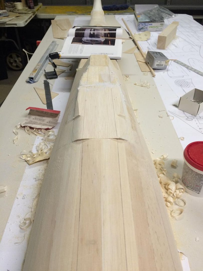
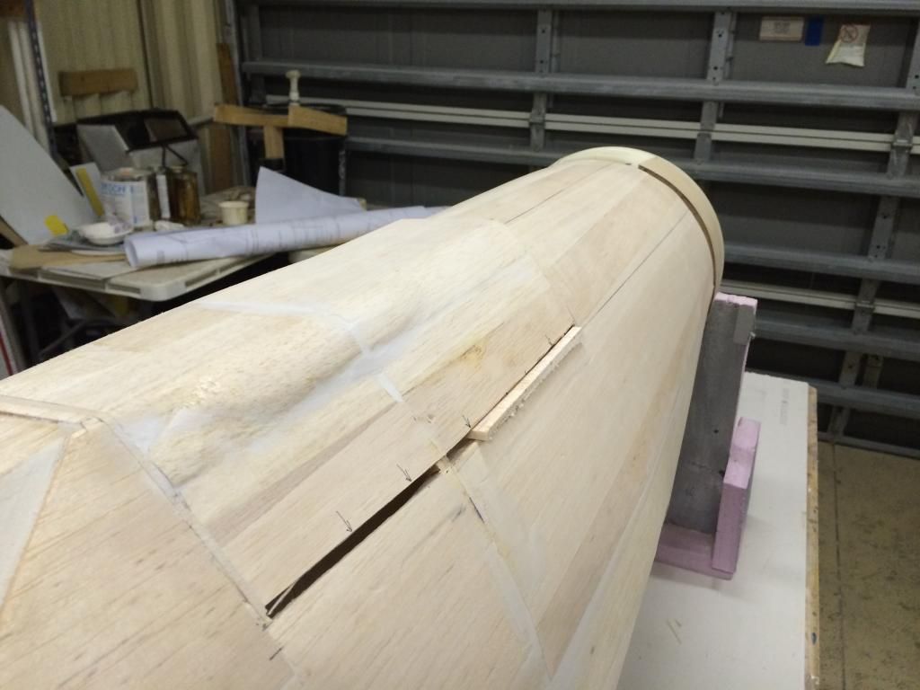
Then after about 5 hours of staring at various photos, plastic models, 3-views and books, i took the plunge and cut the upper blocks for the hood. About 3 hours later i have the first iteration of the hood rough shaped. Ive got a coat of filler in the corners to hep blend in the blocks to the fuselage. Im glad this area is done, but it doesnt look right to me.
Thoughts and opinions?
First up was a few filled pieces to level the top blocks and to get the bottom portion shaped.

It was at this point that i realized the top of the F6 bulkhead was off in shape. F6 was a bit to fat where the balsa block is said to go and it throws off the entire shape of the fuselage there.
So i trimmed the ply bulkhead own and recessed it where i had already put the filler block pieces.

I then reshaped the filler blocks so that they took the tapered shape of the Fw190 fuse.
Then after about 5 hours of staring at various photos, plastic models, 3-views and books, i took the plunge and cut the upper blocks for the hood. About 3 hours later i have the first iteration of the hood rough shaped. Ive got a coat of filler in the corners to hep blend in the blocks to the fuselage. Im glad this area is done, but it doesnt look right to me.
Thoughts and opinions?

 12-07-2014, 08:20 PM
#117
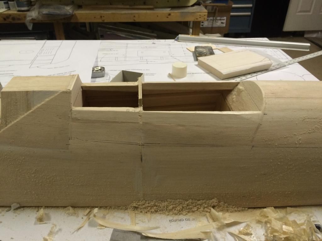
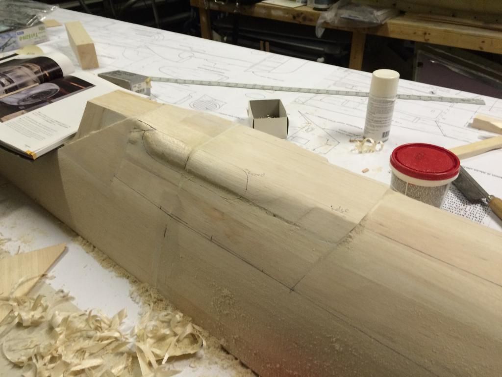
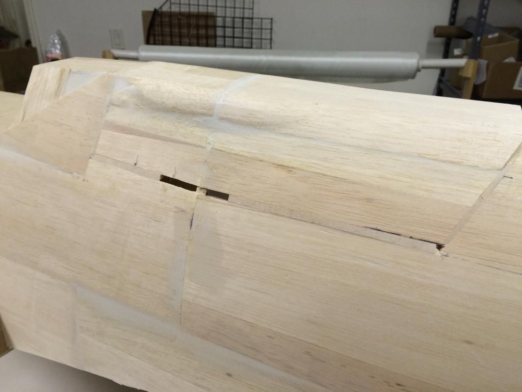
I went back out and looked at the zoukei mura book and some photos on the net and it was pretty obvious it wasnt right. So i hit it with the razor plane and sanding block to just knock it down in shape. It already looks better, but still some more fine tuning to do, i only worked on the majority of the right side.
Here are some photos
Here are some photos

 12-08-2014, 11:20 AM
#118
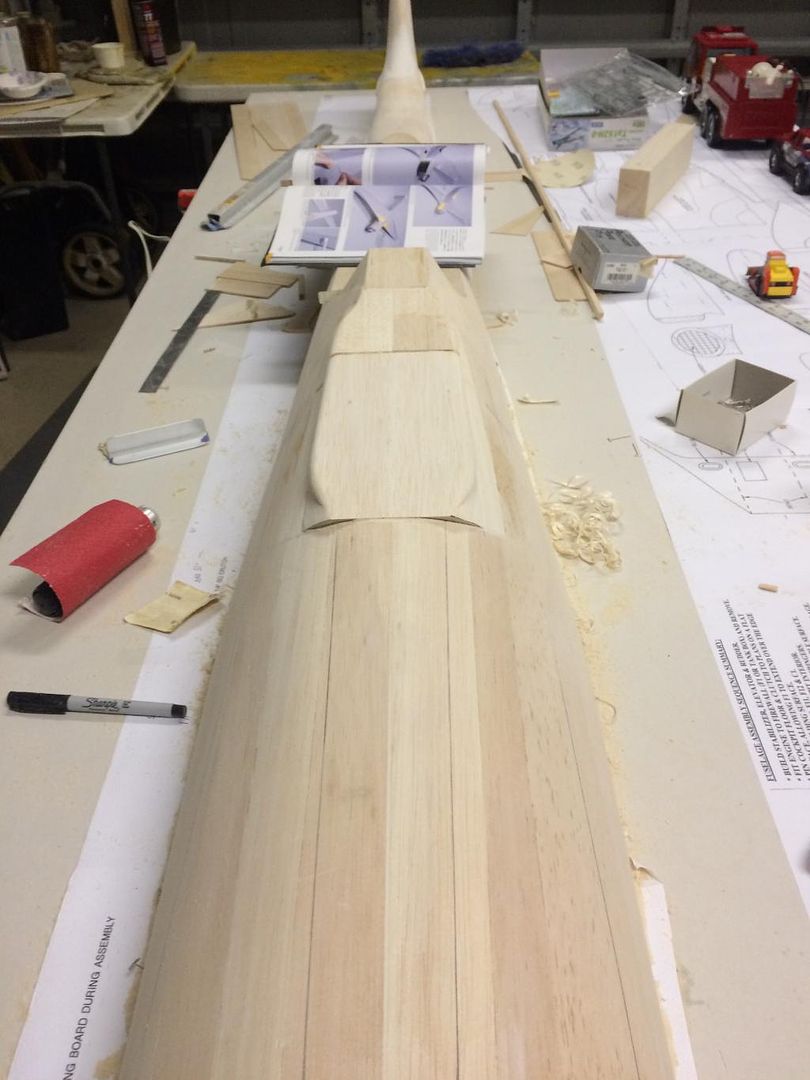
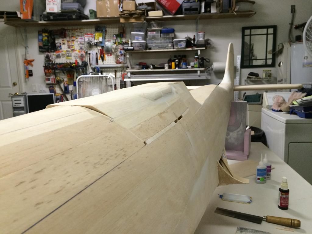
Iteration #2 is now sanded into shape. I am much happier with the version. Ive got some filler drying to help soften the transition on the lower half of the bulges. Once that dries and I'm happy with that, im going to call the gun hood done and continue cutting it free so i can finish building the hatch flange.
I also need to install and shape the transition blocks on the fuselage infront if the gun hood as the plans have the F5 bulkhead round, and its not supposed to.
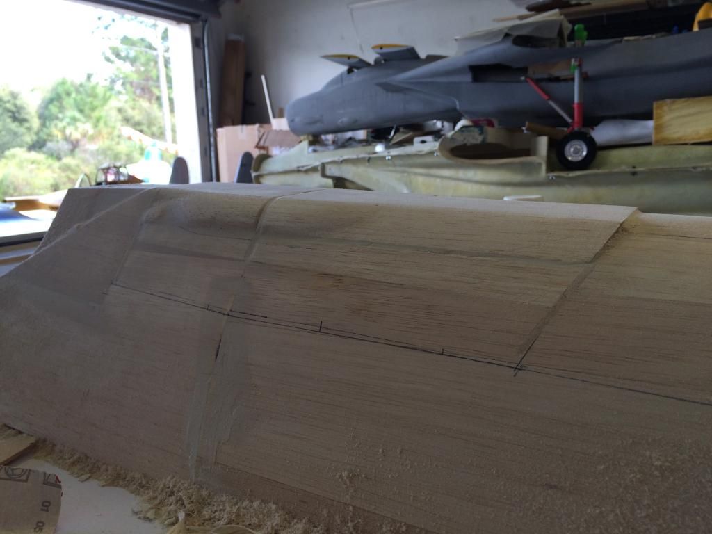
I also need to install and shape the transition blocks on the fuselage infront if the gun hood as the plans have the F5 bulkhead round, and its not supposed to.

 12-08-2014, 01:07 PM
#119
It would seem it is the year of the TA 152 H! Several years ago there were a ton of Fokker DVII's being built, and now with mine, and Jose's completed, along with this one, lots of activity with this design.
That top block was a little bit of a bugger. I just followed Andersen's advice, in that he tells you which line to cut to first, and it worked out pretty good. My Stanley Low angl block plane made short work of it. This is another time when having a plastic model helps, to get that true 3D visual.
That top block was a little bit of a bugger. I just followed Andersen's advice, in that he tells you which line to cut to first, and it worked out pretty good. My Stanley Low angl block plane made short work of it. This is another time when having a plastic model helps, to get that true 3D visual.
12-08-2014, 04:24 PM
#120
It would seem it is the year of the TA 152 H! Several years ago there were a ton of Fokker DVII's being built, and now with mine, and Jose's completed, along with this one, lots of activity with this design.
That top block was a little bit of a bugger. I just followed Andersen's advice, in that he tells you which line to cut to first, and it worked out pretty good. My Stanley Low angl block plane made short work of it. This is another time when having a plastic model helps, to get that true 3D visual.
That top block was a little bit of a bugger. I just followed Andersen's advice, in that he tells you which line to cut to first, and it worked out pretty good. My Stanley Low angl block plane made short work of it. This is another time when having a plastic model helps, to get that true 3D visual.
12-08-2014, 04:34 PM
#121
Ok, i got some more done.
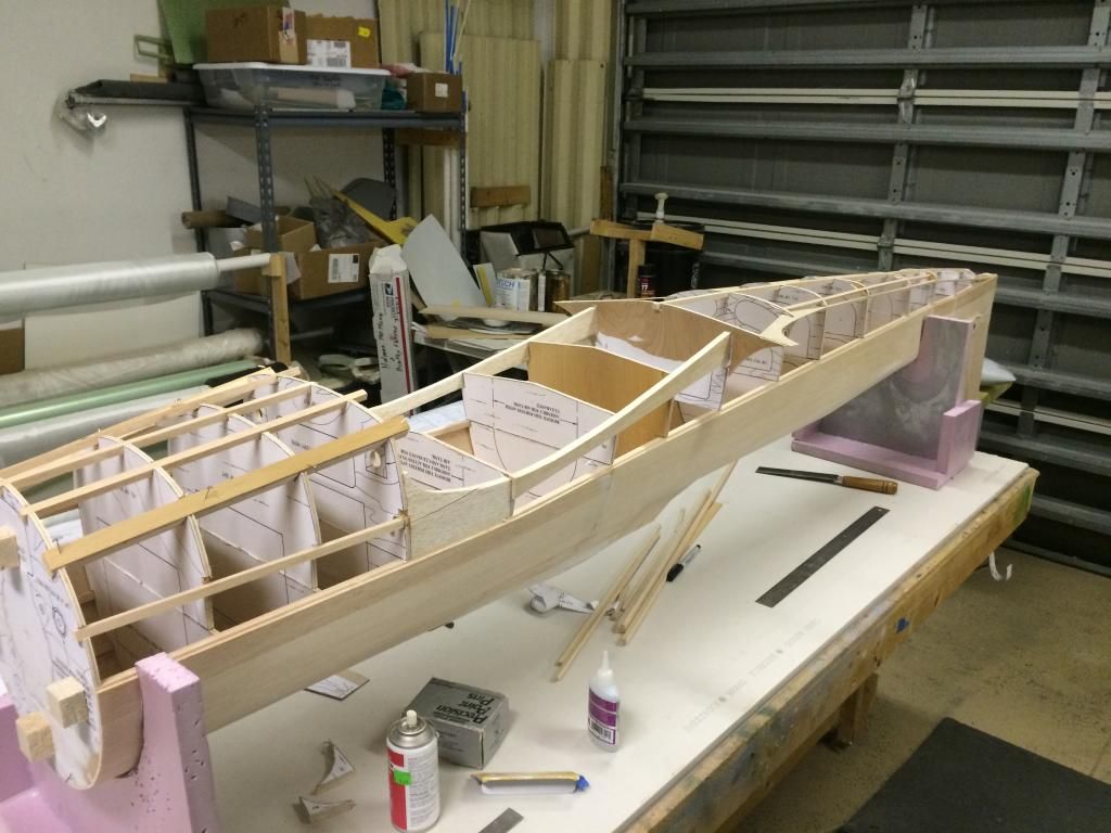
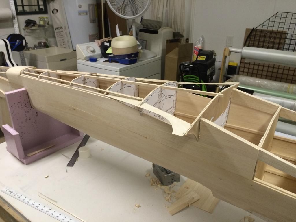
I started gluing on the bottom halves of the bulkheads and installing the stringers.
then more stringers were added (and extended) and the ply rear filet pieces added.
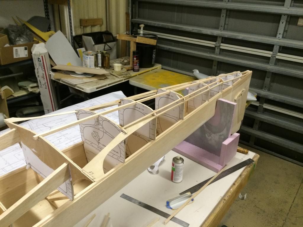
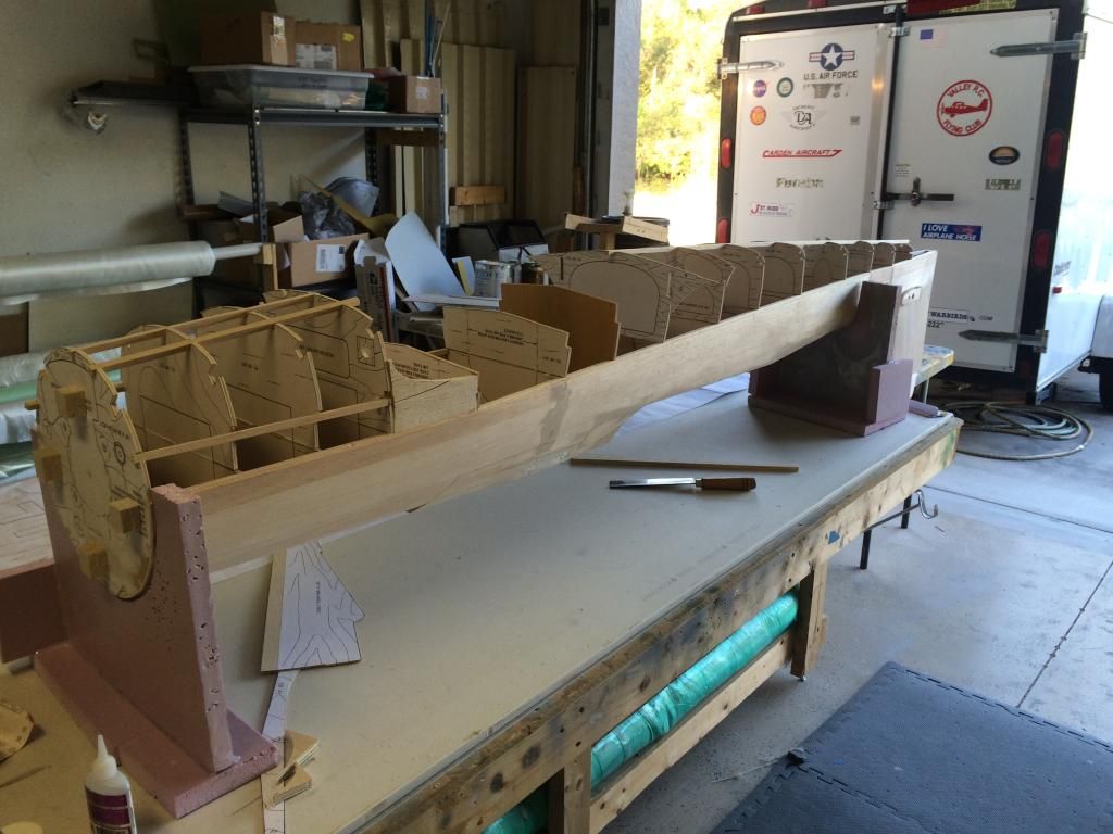
the balsa wing saddle parts were put in place. Here it is with the bottom/sides ready to be sheeted.
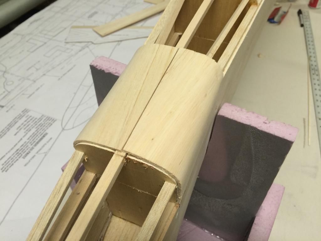
the bottom fuselage extension was sheeted. This was done with only twi pieces. The outside surface of the balsa skin was wetted with tap water and allowed to sit until it started to warp. It was then gentle worked around the curve of the fuselage and glued in place.
the rear fuselage side sheeting was cut and glued to the first bottom stringer on both sides.
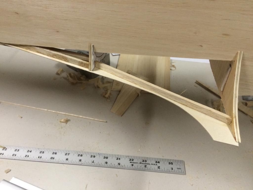
it waa then rolled over in its holders so I could add some stiffener stringers on the ply fillet pieces. The reason i added these was because when the balsa lower skin gets glued to the ply piece, the ply piece will warp and bow. The stringers help prevent that.
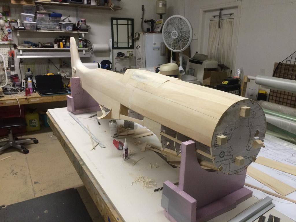
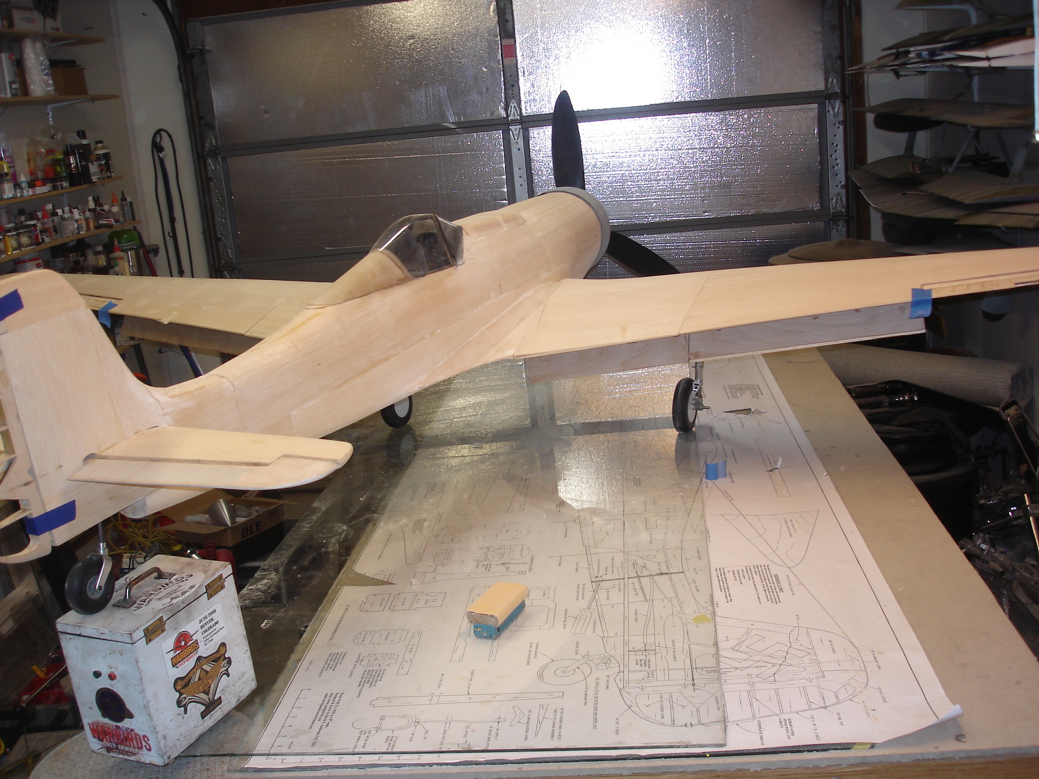
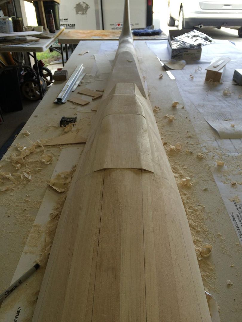
Here is an overall side shot of the fuse as it sits now.
then in prep for sheeting the remainder of the bottom fuse, i wet one side of four sheets of balsa and am leaving to sit while i eat dinner and spend time with the family.
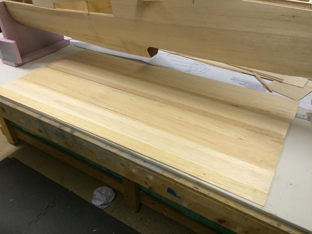
i also got word today that the replacement wing ribs were mailed out today, so they should be here Wed/thursday. My plan is to have 80% of the airframe framed up by the new year. So far I am on track to meet that goal.
I started gluing on the bottom halves of the bulkheads and installing the stringers.

then more stringers were added (and extended) and the ply rear filet pieces added.

the balsa wing saddle parts were put in place. Here it is with the bottom/sides ready to be sheeted.

the bottom fuselage extension was sheeted. This was done with only twi pieces. The outside surface of the balsa skin was wetted with tap water and allowed to sit until it started to warp. It was then gentle worked around the curve of the fuselage and glued in place.

the rear fuselage side sheeting was cut and glued to the first bottom stringer on both sides.

it waa then rolled over in its holders so I could add some stiffener stringers on the ply fillet pieces. The reason i added these was because when the balsa lower skin gets glued to the ply piece, the ply piece will warp and bow. The stringers help prevent that.


Here is an overall side shot of the fuse as it sits now.

then in prep for sheeting the remainder of the bottom fuse, i wet one side of four sheets of balsa and am leaving to sit while i eat dinner and spend time with the family.

i also got word today that the replacement wing ribs were mailed out today, so they should be here Wed/thursday. My plan is to have 80% of the airframe framed up by the new year. So far I am on track to meet that goal.
Last edited by invertmast; 12-09-2014 at 08:00 AM.
 12-08-2014, 08:42 PM
#124
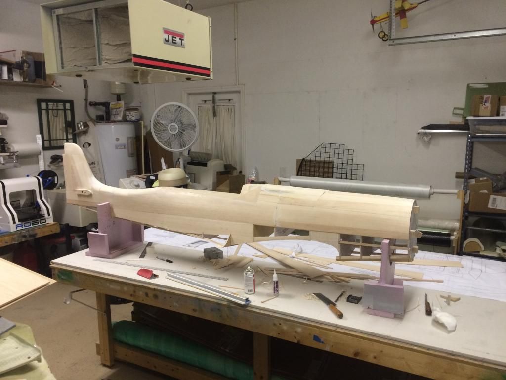
The bottom of the nose and remainder of the sides is sheeted.
the bottom of the tail is also sheeted. There is one last block to install where the tailwheel goes and the bottom is essentially done.
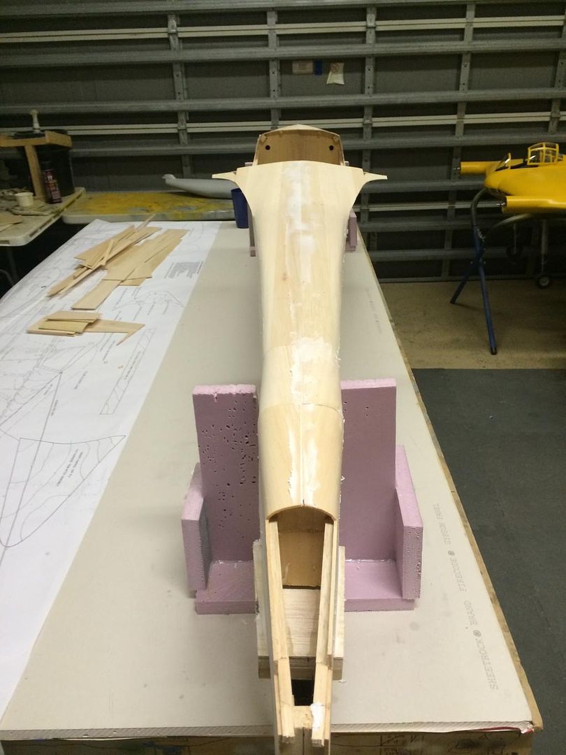
things left to do on the fuselage.
1. Gunhood fairing blocks
2. Wing fillets
3. Gunhood removal and decking
4. Foreward fuse ring
5. Glassing and detailing.
Since i cant do the fillets until the wings are framed, im going to focus on getting as much of the other stuff completed as possible until the wing parts arrive.
12-09-2014, 04:35 PM
#125
The tailwheel block was cut out and shaped. The plans show the semi circle for the tailwheel a wee bit to far forward, so i moved that aft.

There is also a small area around the semicircle where the fuselage bulges out, so i placed some filler in that area to build that up.
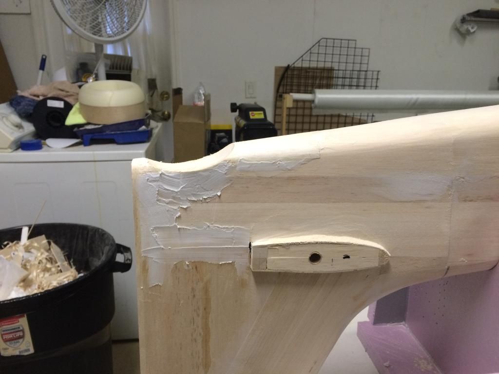
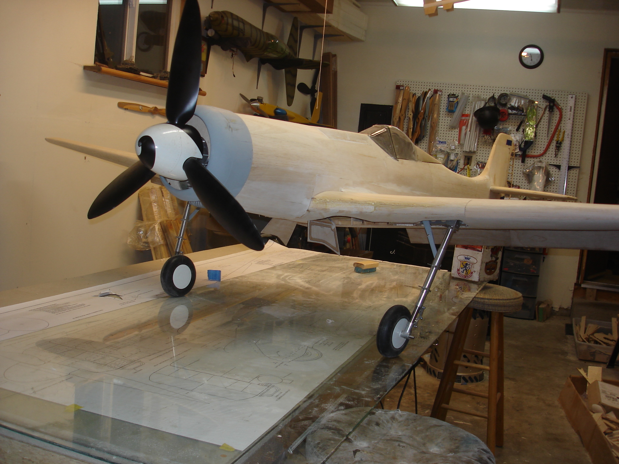
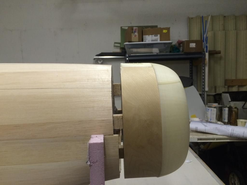
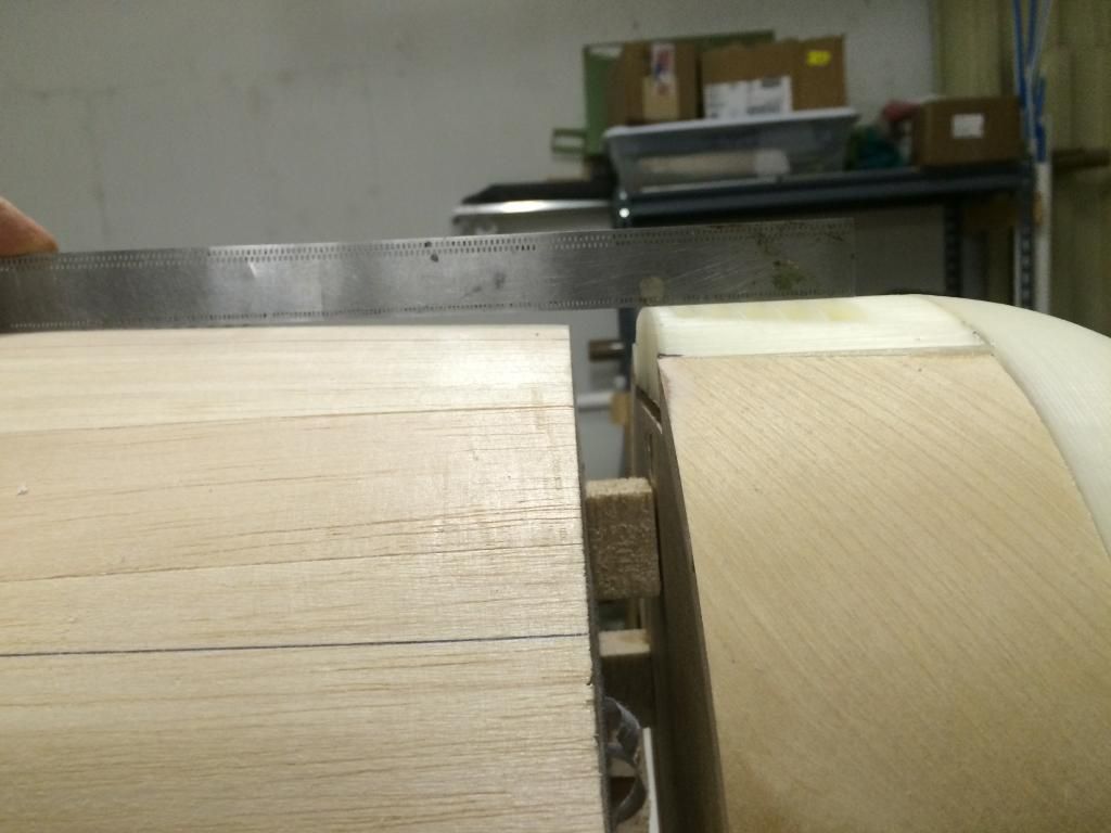
The cowl plug was then tack glued to some 7/8" thick standoff blocks. Eventually a combination if 3D printed parts and balsa will fill this gap.
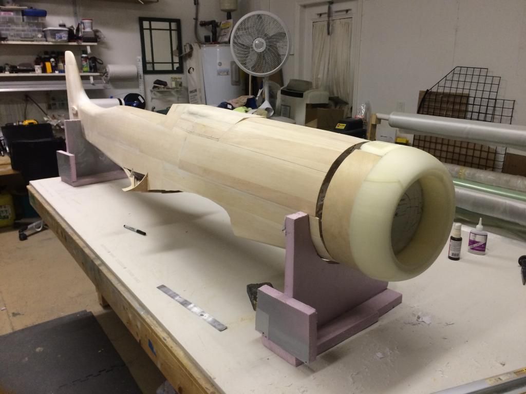
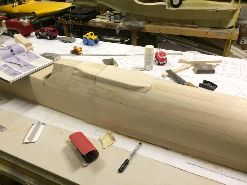
At this point things starting looking a little off (actually i figured it out during the gun hood carving). The printed cowl vents on the top of the cowl plug should follow a straight line from the front of the gunhood to the cowl ring. Mine did not, the printed vent panel was sitting down about 1/8" to much. So i popped the printed part out, raised it 1/8" and got this.
Now that that is done, i can build up this area on the fuse as well. Reason being, the full scale goes from a cropped triangular section at the cowl vent, to round, then back to cropped triangular at the gun hood. Really weird how they did the panel above the engine.
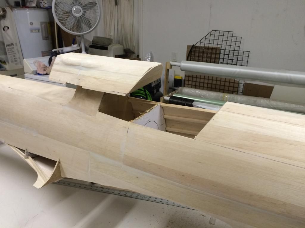
I then decided it was time to remove the gun hood so i could get this done and out of the way.
First up was drawing the split line, the measuring into the gun hood 3/16" for the gun hood base plate. This sliver of balsa was then removed and a balsa plate slid through the slots and glued to the gunhood.
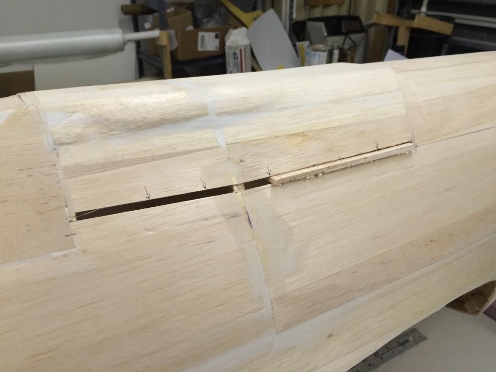
Then the overhang was sanded flush:
And the gun hood cut free.

There is also a small area around the semicircle where the fuselage bulges out, so i placed some filler in that area to build that up.

The cowl plug was then tack glued to some 7/8" thick standoff blocks. Eventually a combination if 3D printed parts and balsa will fill this gap.

At this point things starting looking a little off (actually i figured it out during the gun hood carving). The printed cowl vents on the top of the cowl plug should follow a straight line from the front of the gunhood to the cowl ring. Mine did not, the printed vent panel was sitting down about 1/8" to much. So i popped the printed part out, raised it 1/8" and got this.


Now that that is done, i can build up this area on the fuse as well. Reason being, the full scale goes from a cropped triangular section at the cowl vent, to round, then back to cropped triangular at the gun hood. Really weird how they did the panel above the engine.
I then decided it was time to remove the gun hood so i could get this done and out of the way.
First up was drawing the split line, the measuring into the gun hood 3/16" for the gun hood base plate. This sliver of balsa was then removed and a balsa plate slid through the slots and glued to the gunhood.


Then the overhang was sanded flush:


And the gun hood cut free.
