


giant stik
 03-29-2014 | 01:29 AM
#1

Thread Starter

My Feedback: (1)
Joined: Jul 2005
Posts: 551
Likes: 0
Received 0 Likes
on
0 Posts
From: linden, TN
How much weight is everyone adding to the plane? I've built it as per the manual except I move the fuel tank back into the secondary position and used carbon fiber rods and robart hinges, Ignition and the battery are in the fuel compartment two servos in the tail. Looks like I might have to add about 2 lbs. of weight. the engine I am using is a MT 35 beam mounted. I've read that some are adjusting the C.G. 5 7/8- 7 inches back from the leading edge. Is that correct? Michael
 03-29-2014 | 02:38 AM
#2
My Feedback: (2)
Joined: Jan 2003
Posts: 737
Likes: 0
Received 0 Likes
on
0 Posts
From: Billingsley, AL
I would calculate the CG myself. Don't trust the manual. Should be able to start at about 25-30% of the chord on a straight wing. You can also set the motor out some to offset adding so much weight. Moving the motor(2-3lbs.) out a half inch will make a difference in the weight needed to balance it. The two servos in the tail are at least 3oz. that need to be offset by more than that at the nose.
03-29-2014 | 08:08 PM
#4
My Feedback: (2)
Joined: Jan 2003
Posts: 737
Likes: 0
Received 0 Likes
on
0 Posts
From: Billingsley, AL
A 2x4 might split. It would be OK for checking the CG movement, but I wouldn't fly it that way. Better to use aircraft plywood stacked up. It only needs to be stacked at the mount bolts. Cut 1x1 squares of 1/4in. plywood and drill them. Also 2in. out might be too much. You are moving a lot of weight when you move the motor. What is the chord of the wing? I have an 83in. World Models Super Stunts 60(Stik type plane). I am using a glow GMS .75 that is set out 1/4in. plus the battery is behind the fuel tank and 2oz. of lead on the cheek cowl. The big wide stab. and short nose on the fuse cause the need for weight. It is still a floater.
Last edited by ec121; 03-29-2014 at 08:10 PM.
03-30-2014 | 04:17 AM
#5
Thread Starter
My Feedback: (1)
Joined: Jul 2005
Posts: 551
Likes: 0
Received 0 Likes
on
0 Posts
From: linden, TN
Its an 80 inch wing span. You are right aircraft ply is the way to go. As to how far out to move it I was thinking of using the 2x4 to just see about how far I would have to move it out (its easy to do) and cut it back 1/4 inch at a time till it balances and then make stand offs after I get the measurements does that sound about right Michael
03-30-2014 | 06:11 AM
#6
My Feedback: (2)
Joined: Jan 2003
Posts: 737
Likes: 0
Received 0 Likes
on
0 Posts
From: Billingsley, AL
Should work to get the measurement. I once put a screw in the firewall and hung lead from it to get the correct balancing weight. Had to calculate the CG of a 72in. biplane then see how much weight it took at the firewall. Luckily it turned out my 40cc gasser was close to the right weight. Have you found the correct CG? Need to start there.
03-30-2014 | 08:22 PM
#7
Thread Starter
My Feedback: (1)
Joined: Jul 2005
Posts: 551
Likes: 0
Received 0 Likes
on
0 Posts
From: linden, TN
I've read the manual it states 5 7/8 but some have adjusted it between 6 and 7 inched. I've used a MAC calculator using 25-30% and it comes out less then 5 7/8.more like 4.25-5.1. wing span 80.5 cord 17. has anyone used 1 inch wooden dowels for stand offs? they wont be long ill start at 2 inches and cut them back 1/4 inch at a time just trying to save from having to add lead weight. Also I have to fix the elevator seems that when the servo is moving the elevator up and down the horizontal stabilizer is flexing up and down not good I've redid the elevator twice thinking I might have gotten a robart hinge cocked This is not my first ARF I've put together but this one is A challenge for sure michael
03-31-2014 | 04:24 AM
#8
My Feedback: (2)
Joined: Jan 2003
Posts: 737
Likes: 0
Received 0 Likes
on
0 Posts
From: Billingsley, AL
Dowels will work for standoffs if they are good hardwood. I use plywood or metal. I have some aluminum plate from my old workplace. Lowe's, etc. sell 1in. wide aluminum strips about 1/8" thick. Also washers can be stacked. I would treat the ends of the dowels with thin CA glue once I found the proper length. (You could even glue on a layer of firberglass.) That will soak the grain and help prevent splitting. Don't know about the elevator flexing other than hinges out of line. They could be installed correctly, but out of line. I had to put braces on mine because the landing gear fell out and hit the tail. Not much wood in the built up tail so I installed braces to help my repairs. Had to glue blocks in the framing for the screws. As far as the CG, I would go wit the calculated CG until I flew it. You can always shorten the blocks to move it back later. It isn't fun to fly a tail heavy airplane on its first flights. Too tail heavy will make a really elevator sensitive plane. I have a 50cc Thunder Tiger Extra that I used the manual CG on. Made it really tail heavy. The first flight was all over the sky until I got it sort of trimmed enough to land. Fortunately, it only cost me a broken prop and slightly bent landing gear to get it on the ground. I have double checked the manual CGs or calculated my own since then.
Last edited by ec121; 03-31-2014 at 04:35 AM.
03-31-2014 | 08:59 AM
#9


Joined: Nov 2005
Posts: 12,624
Likes: 0
Received 0 Likes
on
0 Posts
From: Poolesville, MD
I've built 11 of these planes used as club trainers...
Don't use dowels. There will be too much torque on the dowels and the extra length produces a high lever moment.
You can use hard wood if you maximize the contact area as much as possible.
On our club trainers I am using lowely DLE 20 engines. These engines are far TOO light for the plane, yet they power it adecuately for a trainer.
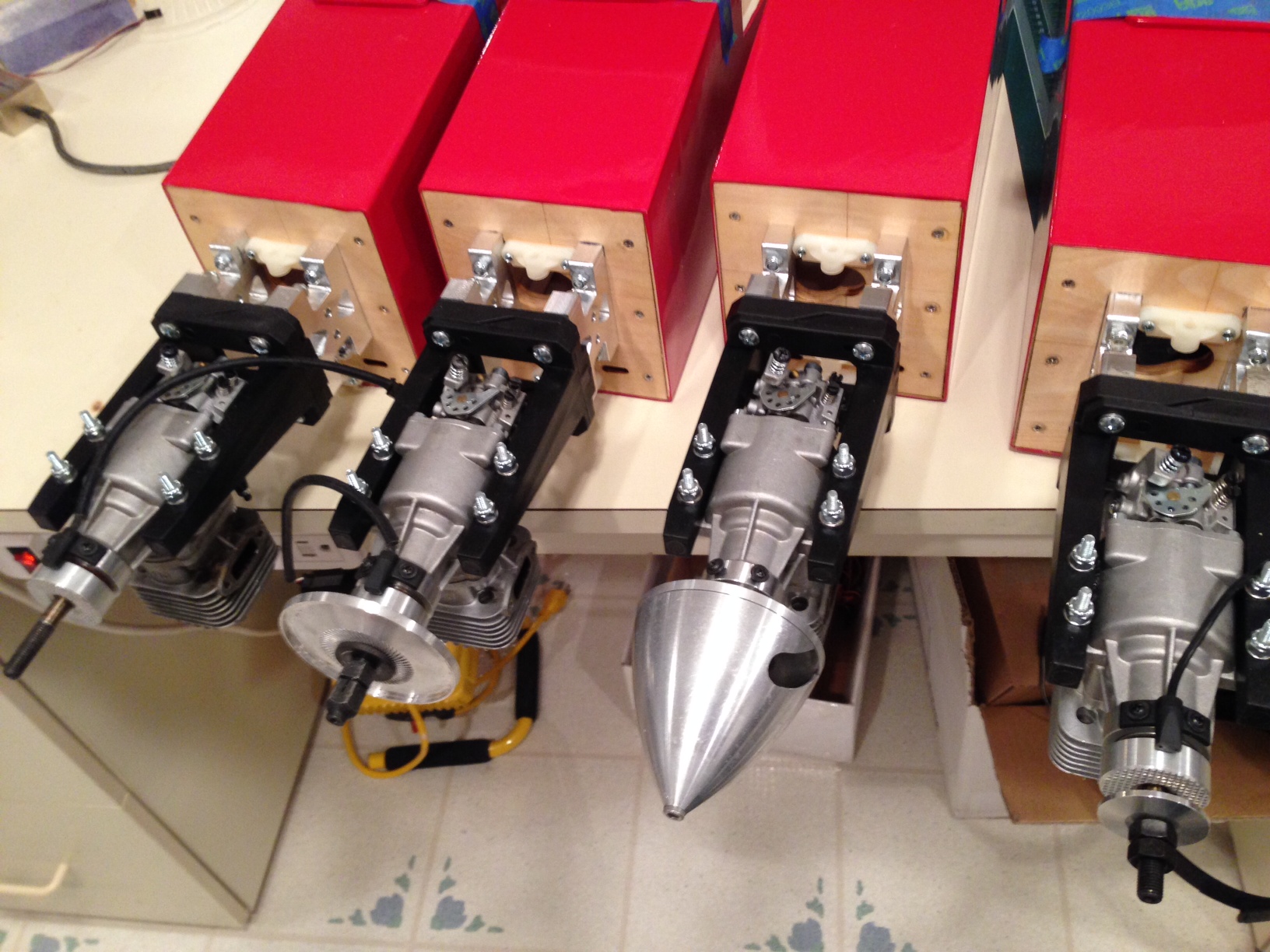
In the picture below you can see how I've moved the engine out much further, to both adjust the C.G. and to permit the use of heavy duty Fults struts in a tricycle configuration ( better for newbies ).
The fuel tank is in the aft position and I have a 4200mAh 9v LiFe pack behind the firewall to power the electronics as well as a 2200mAh 6.6v LiFe packs for the ignition.
Click image to enlarge
Don't use dowels. There will be too much torque on the dowels and the extra length produces a high lever moment.
You can use hard wood if you maximize the contact area as much as possible.
On our club trainers I am using lowely DLE 20 engines. These engines are far TOO light for the plane, yet they power it adecuately for a trainer.
In the picture below you can see how I've moved the engine out much further, to both adjust the C.G. and to permit the use of heavy duty Fults struts in a tricycle configuration ( better for newbies ).
The fuel tank is in the aft position and I have a 4200mAh 9v LiFe pack behind the firewall to power the electronics as well as a 2200mAh 6.6v LiFe packs for the ignition.
Click image to enlarge
Last edited by opjose; 03-31-2014 at 09:02 AM.
03-31-2014 | 09:04 AM
#10
Thread Starter
My Feedback: (1)
Joined: Jul 2005
Posts: 551
Likes: 0
Received 0 Likes
on
0 Posts
From: linden, TN
well I've have wooden dowels as stand off 2 inch long and it still needs weight how much I don't know yet maybe this MT 35 is lighter then I think I have a Ryobi 31 converted to electronic ignition maybe it weights more the MT35 is 1.8 lbs would it hurt to leave the stand offs at 2 inches?
03-31-2014 | 09:12 AM
#11
Joined: Nov 2005
Posts: 12,624
Likes: 0
Received 0 Likes
on
0 Posts
From: Poolesville, MD
Been there, tried that, found it problematic.
Avoid wooden dowels. There is not enough contact area nor anti-flex strength to avoid the torsion problems with the engine out pretty far.
On my first build I created wooden standoff blocks similiar to the aluminum ones you see in the picture to solve the dowel problem.
That worked. Later another club member created the CNC standoff blocks in the picture which are even better.
At worst, zip tie your battery packs to your standoff mechanism.
Remember that these planes were designed around the relatively heavy Fuji BT-32B engines that come in at 4.5lbs in weight each... and they mounted with the included standoffs and wood.
Use a BIG battery pack as far forward as possible too. This helps a lot.
You'll need something large anyway to power all of those servos, particularly if they are digital high torque servos. I clock momentary 8.5A power draw bursts when there is resistance on more than one surface.
Last edited by opjose; 03-31-2014 at 09:16 AM.
03-31-2014 | 08:20 PM
#12
Thread Starter
My Feedback: (1)
Joined: Jul 2005
Posts: 551
Likes: 0
Received 0 Likes
on
0 Posts
From: linden, TN
Ok wooden dowels are a problem then. Back to square one. What can I use to move the engine out to keep from adding a lot of lead weight? I have both ignition and receiver batteries in the fuel compartment. What about building a box around the dowels epoxied, to were I can epoxy weights into it that would add support to the dowels like an engine box you see on other airplanes
04-01-2014 | 02:29 AM
#13

You sure want to go to a lot of extra work, just so you can use dowels. Why ?
As has been stated, forget the dowels. Use hard ply or hardwood. Cut it into 3/4" squares and drill a hole in the center. Place a square behind each engine bearer mounting hole and mount the engine. Use a 1/4" thickness.
If it balances, your done. If not, add another square and repeat.
As has been stated, forget the dowels. Use hard ply or hardwood. Cut it into 3/4" squares and drill a hole in the center. Place a square behind each engine bearer mounting hole and mount the engine. Use a 1/4" thickness.
If it balances, your done. If not, add another square and repeat.
04-01-2014 | 08:15 AM
#14
Joined: Nov 2005
Posts: 12,624
Likes: 0
Received 0 Likes
on
0 Posts
From: Poolesville, MD
Yup you can do what Tom suggests. That will work well.
You can also build a NEW "box" if you choose. Just make sure you use relatively thick hardwood, and use tri-stock bracing.
Note that the Stik's original firewall has aluminum angle bracing on it too.
Don't design around the dowels though.
You can also build a NEW "box" if you choose. Just make sure you use relatively thick hardwood, and use tri-stock bracing.
Note that the Stik's original firewall has aluminum angle bracing on it too.
Don't design around the dowels though.
04-01-2014 | 11:39 AM
#15
Thread Starter
My Feedback: (1)
Joined: Jul 2005
Posts: 551
Likes: 0
Received 0 Likes
on
0 Posts
From: linden, TN
going to do away with the dowels. The engine sticks out to far for my liking so I see just how much weight I will have to add went and picked up some old tire weights I will melt them down in a tin box that way it will mount flat. Now the engine mounts have A hole in the sides for what ever reason what do you think about drilling a hole in the flat lead and using a bolt and lock nut to hold the weight on
04-01-2014 | 12:47 PM
#16
Joined: Nov 2005
Posts: 12,624
Likes: 0
Received 0 Likes
on
0 Posts
From: Poolesville, MD
What engine mounts are you going to use? The ones that came with the plane?
Yes you can do as you said to hold the weights on. Remember though that lead is pretty soft, so you may want to provide at least two bolt points and use large washers such as fender washers to retain the metal.
BTW: I don't know how you are going to heat lead in a tin box.
The melting point of tin is 449 degrees F, while the melting point of lead is 621 degrees.
There is a company that sells a product called "Liquid Gravity" for RC'ers. It is nothing but fine lead shot. You mix it with epoxy to apply it to any surface, nook or cranny.
You could put the tire weights in a wooden box and affix that to the firewall or engine mount, or you could do the same and put it behind the firewall in the compartment.
If you check the photo I posted above, you'll see that my engines are pretty far out front. I doubt your engine is lighter than my DLE 20's.
Don't forget that you can turn the needed weight into "useful" weight by installing BIG battery packs in the compartment and on the firewall.
04-01-2014 | 04:50 PM
#17
Thread Starter
My Feedback: (1)
Joined: Jul 2005
Posts: 551
Likes: 0
Received 0 Likes
on
0 Posts
From: linden, TN
Sorry I should have said I was going to melt the lead in my lead melting pot. As far as the tin goes I go to dollar store and get one of those tin playing card holders pour the melted lead in it now I have a flat 1/4 inch lead bar I can cut. I've seen that Liquid Gravity that would be the way to go I think I will do away with the dowels and mount the engine to the fire wall and balance it and hope it comes under 14 lbs as far as batteries Iam using a 4.8 volt 2000 nimh for the ignition and a 6 volt 2500 nimh battery for the receiver mounted up front by the fire wall the engine mount I am using are large T type don't know the name
04-01-2014 | 07:57 PM
#18
Thread Starter
My Feedback: (1)
Joined: Jul 2005
Posts: 551
Likes: 0
Received 0 Likes
on
0 Posts
From: linden, TN
well I mounted the engine back the way it is suppose to bee and used 2 1/ lbs. of lead in the fuel compartment balanced it at 6 inches from the leading edge just have to put the ignition module back in it is just a little nose low now I have to redo the elevator it was binding causing the horizontal to flex up and down when the elevator was moving should be able to fire it up this week thank you all for your advice as all ways you are the best people to ask for advice this is my second giant stick the first one crashed do to a broken elevator rod I also fly a USS ( ultra spad with stick a Ryobi 31 converted stick)its not fast but plenty of power michael
04-02-2014 | 09:14 AM
#19
Joined: Nov 2005
Posts: 12,624
Likes: 0
Received 0 Likes
on
0 Posts
From: Poolesville, MD
At worst put in two 6V 2500 NiMH packs and connect them in parallel to give you an effective 5000mA 6v pack.
You are running EIGHT SERVOS on this plane plus the receiver.
A single digital servo can draw 2000mA as it approaches stall. Typical momentary bursts are in the 1000mA to 1200mA range as the servo reverses direction.
Likewise a single high torque analog servo will draw up to 1500mA as it approaches stall and typically hits 750mA during direction changes.
A single 6v 2500 pack is begging for brownouts even if your flight times are fine.
This is a giant scale plane and needs giant scale power for the electronics.
I was originally using 8800mA 9.9v LiFe packs regulated ( 20A ) down to 5.5v, but then switched to a single 4200mA 9.9v LiFE pack after stress testing.
I typically use 2500mA 6v packs on much smaller planes... e.g. .50's or even down to .40's.
Your additional weight sounds about right given the difference between your engine and the FuJi's much higher weight.
Adding weight should be "useful" weight when possible... and bigger packs give you plenty of flight time, plus the safety factor, while giving you the extra weight you want.


