


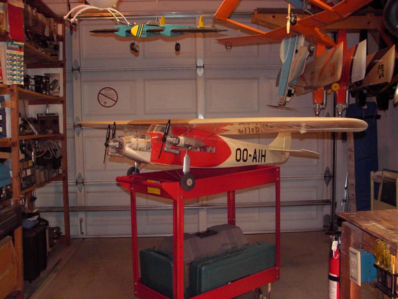
A Ringmaster Bi-Plane
 10-28-2013 | 04:42 PM
#51

Thread Starter

Hi LOU.
Thanks for the input. yeah the wing is a little more than double. I did the same thing to the tail feathers. I would have to go back and look up the areas and ratios myself, but I seem to recall 22% (or slightly more) of wing area for the horizontal and same the vertical is sized just like the horizontal. I also stretched the tail out a bit. So I should have more tail volume than The original. I am hoping that works.
I intend to place the bellcrank in the fuse. I closed up the lead out cable holes in all the ribs before I started building the wings. I will also use an adjustable lead out guide mounted to the inboard side strut for fore and adjustability. reading your post made me think maybe I should also be able to move it up and down? Never thought of that before.
You have given me some food for thought. Thanks.
I hope to start the struts this weekend. It looks a little tall on paper, but I am going to have one chord of separation between the wings nonetheless.
This project has had some challenges already, and I know there will be more. And then it will take some time to get it adjusted for best performance after it's maiden.
 11-02-2013 | 06:42 PM
#52
Thread Starter
Well I am attempting to puzzle out top alignment.
So here is what I have done so far.
I put the wing building rods back in both wings to have a common reference point. I had to buy 2 more rods. I also had to cut the rods in halve that go into the bottom wing. The ply plates for the front wing bolts interfered, so cut resolved that issue.
I bolted the bottom wing on the fuse, and then set the wing rods on the rod holders. That took a bit of playing with. I had to move the rod holders way in as the wing (bottom) would twist to easily. Next thing was getting the aluminum rods clamped down good. Rubber bans proved the easiest way, just looped them over the wing rods.
I then cut some foam board into sort of struts. They set on the bottom wing building rods. I had to notch for the spars. I then pinned the foam struts to a couple of ribs and set the top wing on. Now I will try to get both wings in exact alignment.
Oh and the top wing is set forward of the bottom wing 1.75" There is also a full root chord of separation between the 2 wings.
I will instal small ply pads where the real struts will attach.
So what I have done is just to kind of wrap my handful of brain cells around mounting and alignment.
A disclaimer at this point.
Not even the tiniest drop of glue has been harmed at this point of alignment and mounting. A dry run.
Ken
11-03-2013 | 12:49 PM
#53
Thread Starter
Well I am attempting to puzzle out top alignment.
So here is what I have done so far.
I put the wing building rods back in both wings to have a common reference point. I had to buy 2 more rods. I also had to cut the rods in halve that go into the bottom wing. The ply plates for the front wing bolts interfered, so cut resolved that issue.
I bolted the bottom wing on the fuse, and then set the wing rods on the rod holders. That took a bit of playing with. I had to move the rod holders way in as the wing (bottom) would twist to easily. Next thing was getting the aluminum rods clamped down good. Rubber bans proved the easiest way, just looped them over the wing rods.
I then cut some foam board into sort of struts. They set on the bottom wing building rods. I had to notch for the spars. I then pinned the foam struts to a couple of ribs and set the top wing on. Now I will try to get both wings in exact alignment.
Oh and the top wing is set forward of the bottom wing 1.75" There is also a full root chord of separation between the 2 wings.
I will instal small ply pads where the real struts will attach.
So what I have done is just to kind of wrap my handful of brain cells around mounting and alignment.
A disclaimer at this point.
Not even the tiniest drop of glue has been harmed at this point of alignment and mounting. A dry run.
Ken
The first 2 pics are duplicates but I can't remove them.
Last edited by flyingagin; 11-03-2013 at 12:56 PM.
11-03-2013 | 12:58 PM
#54
Thread Starter
The other thing both the wife and I noticed, the wing gap seems excessive, even though it measures out correct. We think the fuse depth is what gives this impression. I think the way to solve this is to deepen the fuse. Both by just add some depth and by a tallish turtle deck.
It was suggested on another site that I lower the top wing 1" and to use a tallish turtle deck. I will do both.
Ken
It was suggested on another site that I lower the top wing 1" and to use a tallish turtle deck. I will do both.
Ken
 11-06-2013 | 02:49 AM
#56
Thread Starter
11-08-2013 | 03:00 PM
#57
Junior Member
Joined: Nov 2013
Posts: 6
Likes: 0
Received 0 Likes
on
0 Posts
Just registered yesterday 11-7-13 so am way behind on this thread but enjoyed it immensely. Ken are you still fabbing away on the RM Bipe? Your engineering skills are impressive. I built 2 planes last year without a board and wound up with a warped outboard wing on my bigger plane. It's a modified Viking - put flaps on it and changed the rudder. Bould a modified Vampire with rounded tips like the Shoestring. The geometry came out good on it. Made a wingboard for 2 home designs and got them straight. Built a large combat wing for fun and it works too. Rebuilt a RM. a Shoestring. Flite Streak. Combat Cat while messing with the first two. Finally got color on all the planes but haven't fully completed any. Getting close. Want to see that RM of yours with some cover and color. WC
11-08-2013 | 04:25 PM
#58
Thread Starter
Hi Kozmo77
Welcome aboard the site and my thread. Glad to have you.
Here is the building board I am using. It is available on Tower Hobbies for $29.99 plus shipping. Worth every penny too.
Great Planes Pro Building Board 16x48x3/4" http://www3.towerhobbies.com/cgi-bin...&I=LXPF36&P=ML
I have a magnetic board I lay on top of it. The 2 in conjunction are fantastic. Unfortunately the magnetic board has been unavailable for a long time.
I also have several (3) planes 90% to 99% finished awaiting test flights. Those are RC planes.
I think I may miss working on this plane this weekend. I want to build a pair of parallelograms type jigs for doing wing and stab alignments. I have about 4 more biplane projects I want to do. A 1/4 scale RC Pitts. I am kicking the ideal for a Rc Tri motor biplane and a CL tri motor biplane. Plus I have a pair of biplane wings needing a new home.
Ken
11-10-2013 | 03:28 PM
#59
Thread Starter
Slow progress this weekend. The wife and I did not have much running around to do. We basically stayed home and did nothing. We were both just worn out I think. So I got next to nothing done yesterday. Sometimes that is good, you just got to chill out and rest.
I have started physical therapy for my back, it should help at some point.
In regards to the parallelograms jigs for doing wing and stab alignments. A base and 2 parallel runners would make aligning bi plane wings much easier. I did make a tripe to Lowes looking for CHEAP yardsticks to make them out of. Well I found them but they did not have perfectly straight edges, so i gave up on the immediately. Angle aluminum would work good but was way to spendy. But about a month ago someone tossed a 1" square piece of steel tubing in front of the parking spot. It has just been laying there in the grass and weeds. So when I got home I took a good look at it. It is straight, not yet rusted. In short it is perfect and free, so it is now in my patio area. I will measure out pieces and start hack sawing it. I will make a jig to drill all the holes exactly the same. Check alignment of my drill press and have at it. I will post some pics. But that is a next weekend project.
Now back to the bi plane.
I did get some small amount done today. I made and epoxied in the front mounting plates for the inter plane struts. Next I have to make the back plates. They are 1/16" birch ply. Will need some gussets and possibly reinforcement. Once the back plates are in then I will need the pair of parallelograms jigs to set the wings. Then I can start making the interplane struts. This way I should be able to get the struts almost dead on, or so I am hoping.
Pic 1 is the bottom wing. The mount plate is in the 4th rib bay from the ends and is positioned towards the top of the wing The outboard side is wider and is where the strut will attach. I think I am going to put the front leg of the strut real close to the spar as that is the strongest point. The back leg will mount real close to the T.E. stock.
The second pic is the top wing The mount plate is in the 3rd rib bay from the ends and is positioned towards the bottom of the wing. The strut mount point is the same as the bottom wing.
By offsetting 1 rib it makes the struts lean out wards a bit. I don't know if it will be enough to help stiffen the wing wings in side to side play, but I like the look.
Ken
11-11-2013 | 07:13 PM
#61
Thread Starter
Ken
11-14-2013 | 12:42 PM
#62

My Feedback: (1)
Ken was just checking back in and noticed the gap chord. I agree with both you and your wife the gap chord is excessive to the point its going to look very odd indeed. And I believe it would be a mistake to deepen the fuselage turning the airplane even more into a characture airplane and not even very recognizable as a ringmaster.
I am not talking about aerodynamics, Hang the aerodynamics if it does not look right you will never be happy. I am going to suggest you do not deepen the fuselage more and that you lower that top wing until it looks right to the eye. Another suggestion is even though it is not needed aerodynamically is to add some mild dihedral to the lower wing as this will improve the looks immeasurably.
I have done many "kit Bashes" over the years and one of my goals was always avoid loosing the identity of whatever it was that was started with.
John
11-14-2013 | 05:23 PM
#63
Thread Starter
Hey thanks for checking in John. It is good to hear from you.
I intend to reduce the gap. I just could not stand to look at that huge gap you could drive a semi through. As far as the deeper fuse what I had in mind was more of a flaring of the top curves to fool the eye. Still easy to do or not at this point. I will set the wings and give it the critical eye. I do not want to lose the ring look. I am hoping it instantly say ring to on lookers. That is for me a real challenge to not mess up. Hopefully it will be close enough. Their are so many others so much better than I am.
It would take a bit of effort at this point add dihedral to the bottom wing, but I sure thought about it early on. The little CL bi-plane I built as a teen had some bottom wing dihedral plus a swept back top wing. I wish I had some pics of it. Really sharpens the looks.
I am hoping to scratch build three more bi-planes in the next year or 2. One a scale Pitts. But 2 designs of my own. 1 RC and 1 CL. Are you game for tri motor bi-planes? I have done a fair amount of spreadsheet work on the former. Check out the Boeing model 80.
Ken
11-14-2013 | 08:11 PM
#64
My Feedback: (1)
Oh man Ken a controlline 80A would indeed be an awesome project, that would be so cool! I have done quite a few multi engine projects up to six engines but just two tri motor ships an eighty five inch span Stinson and a sixty inch Fokker F7. The Fokker has OS LA 10's and external scale controls and the Stinson has OS 25AX's.
I have only messed with one controlline multi engine in the early sixties, it was a Berkeley Douglas A-26 and has two cantangerous Fuji .29's. Man that thing chased me across the circle more times than I care to admit. That was the last time untill recently I am finishing up a little profile p-38 with a pair of Enya .09's. Hope I,ve learned a little more in the meantime on how to keep a multi on the lines
That Boeing project of yours is very exciting.

John
I have only messed with one controlline multi engine in the early sixties, it was a Berkeley Douglas A-26 and has two cantangerous Fuji .29's. Man that thing chased me across the circle more times than I care to admit. That was the last time untill recently I am finishing up a little profile p-38 with a pair of Enya .09's. Hope I,ve learned a little more in the meantime on how to keep a multi on the lines
That Boeing project of yours is very exciting.
John
Last edited by JohnBuckner; 11-15-2013 at 03:08 PM. Reason: Well I give up something has changed and I can no longer post photos
11-16-2013 | 10:01 AM
#65
Thread Starter
Wow John, that Stinson Trimotor Is really cool. Great lines. Sharp model.
I spent a lot of brainstorming time on the Rc Trimotor Bi-plane. I kept bouncing around on motor size and thus airplane size and still am to some degree. I am thinking .15s to .25s two strokes for cost control versus 4 strokes. I would not try to model the Boeing model 80. It is just inspiration. My intent was more as a Sig Kadet variant. I think 3 .15s should work for around 1200 to 1300 square inches. Should be close to the power of a single .45, which is the power level of a Kadet SR. Another floater just like the Kadet SR. Just smaller span and chord. 10 inch chords. 54' bottom span and 66" top span for 1200 square inches.
To solve the 1 chord gap issue and still not have an overly deep fuse, the solution I came up with is to make the bottom wing and inverted gull wing much like the f4u carrier plane of WW2. At first I thought a gull wing top wing, but the inverted gull wing bottom wing would look better and be more practicable engineering wise I think in it that also allows for short main gear struts.
So since you last post I have been thinking about the CL version. And you know it just has to look like a Ringmaster variant. Keep the taper of the wings like the RM with maybe a straight section out to the engine nacelles and then taper. Same tail as the RM.
Perhaps it makes since to shoot for the same size planes and just build both at the same time. 2.4 radio for throttle. A near carbon copy of fuses except for wing saddles. Symmetrical foil for CL version and Flat bottomed Kadet foil for RC version.
A big concern for me is excessive line pull for the CL version. Would .15 or maybe .20s be enough? Lightweight slow flier would go a long way in reducing excess line pull. I just don't think my back can handle to much pull.
Silk and dope finish. Flying wires mandatory. Pictures of passengers in the windows in period dress (late 20s) also mandatory.
I will have some time late this week to draw out and post my ideals (again). I can't find my original drawings.
I love the triple vertical tails but hate the unequal wing chords.
This is one of those ideals I just can't seem to shake. I first conceived of the RC version over a year ago.
Maybe I should start new thread in the multi engine section of the proposed project?????? I will certainly need the input and advice of better more experienced builders and designers than I am. Hint hint John.
.Ken
Last edited by flyingagin; 11-16-2013 at 10:06 AM.
11-16-2013 | 10:42 AM
#66
My Feedback: (1)
Thanks Ken for the kind words. OK now I totally get it on the trimotor thing and I think what you are going for is what I call a Characture airplane and not really ment to represent anything. I have done some along that line of thought and you know what I think that kind of ship can be totally cool. Ya go for it a big tri/bi plane really offers a ton of cool things to dream up.
I am thinking a ship of that size three 15/20's would work out just fine but the only problem with that is there are simply not many left in that displacement and likely choice would be the OS LA-15.
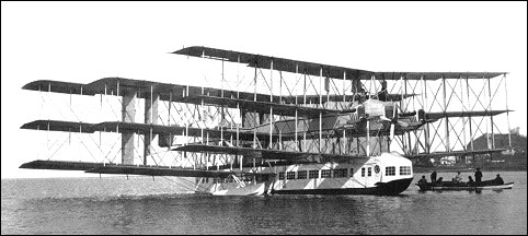
You know one of my dream projects and I know I am not likely to ever get to but that does not mean I can thourghly dream up the design. An that is the only Caproni CA-60 with nine wings (a triple set of triplanes) no tail surfaces (pitch and roll controlled by wing surfaces) an eight engines, Oh yea its a flying boat.
John
I am thinking a ship of that size three 15/20's would work out just fine but the only problem with that is there are simply not many left in that displacement and likely choice would be the OS LA-15.
You know one of my dream projects and I know I am not likely to ever get to but that does not mean I can thourghly dream up the design. An that is the only Caproni CA-60 with nine wings (a triple set of triplanes) no tail surfaces (pitch and roll controlled by wing surfaces) an eight engines, Oh yea its a flying boat.
John
Last edited by JohnBuckner; 11-16-2013 at 10:53 AM.
11-16-2013 | 11:19 AM
#67
Thread Starter
Holy cow John. I just googled Caproni CA-60. That was not a float plane, that was a flying house boat!
Now that would make one heck of a project. Way beyond my abilities.
For engines I see two manufacturer choices that would not be bank busters, and really know next to nothing about either one. Fox .15s or .25s. Or ASP. their .15, 21, or .25 (cheap). I have enough worn out engines to trade in at Fox for half off to make them a contender. The OS LA-15s would be bank busters (3). But would be the lightest choice.
I think .25s would be pushing the power and weight a bit so really only .15s or .21s.
A real show stopper for me has now been removed. I now have a small band saw. That along with the disk/belt sander makes makeing a million and one (well maybe only 60+) wing ribs feasible.
Ken
Ken
11-17-2013 | 04:20 PM
#68
Thread Starter
I was lazy yesterday.Did a lot of other things that were productive, but never went near the plane.
Today I got off my lazy butt and got busy on the parallelogram jig. I SHOULD HAVE STAYED LAZY!!!!!!!!
I totally screwed it up. I have one parallelogram built. IT AIN'T RIGHT!!!!!! The wing support arms are off about 3/32 front to back.
I made a jig to drill all the holes in exactly the same locations. I used a 1/4 bolt as an indexing pin for each hole. I have checked and I have holes that do not perfectly aligned and found one the was a full 1/8" off.
The jig I made has a fence and a indexing pin hole. I checked and trued my drill press. My jig is very securely clamped to the drill press table. I marked the working face of each piece and also the front of each piece.
But I ended up spending hours turn 3/4" square steel stock into garbage.
I do not know where I screwed up. I did not rush this. I spent a lot of time brainstorming it out.
I have gone over my steps and set up, and just don't understand how I could have had holes out off alignment with each other.
I am so p***ed off.
I will post 1 or 2 pics here, but I think I need to open a new thread in the Questions and Answers section. maybe someone can set me straight.
Ken
11-24-2013 | 06:28 PM
#69
Thread Starter
I will try to get back to the plane by thanksgiving day.
I did work on the parallelogram jig . I cut new arms yesterday and trued a face on each to be tottaly straight. I drilled them today. Lots and lots of holes. !/2" spacing on all of them for lots of adjustment range. I made them out of 1/4" ply so now I need shorter bolts to assemble it and check if I got right this time.
Mostly other things have been going on.
I am wrapping up a test trial of a SCS (Spinal Chord Stimulator).
I have been having bad lower back pain and really bad nerve pain (neuropathy) pain in my legs and feet. I have six bad disk. Three in the neck and 3 in the lower back. The ones in the neck are in worse shape but it is the back that has been hurting so much.
Nothing gave me any relief. The Dr tried deadening the nerves. That had no effect whatsoever. So SCS (Spinal Chord Stimulator) trial was recommended.
The leads were temporarily implanted Thursday morning. Rather painful as I was fully awake with just a loco. The leads exit my back and are taped. The Neurostimulator is hung from a velcro strap at my side. It is controlled by a remote control.
Holy crap was I sore Thursday and Friday. But Thursday was just a real bad day. Man was I miserable. This was from having the leads put in though.
But there was NO NERVE PAIN, at all. Friday I was still sore and hurting from the procedure, but not as bad. I had very little nerve pain and moderate back pain.
Then Saturday we had to go to the store. Got a flat tire on the way. No choice but to change it. I had the SCS turned off while driving and changing the tire. Only a little PT cruiser, but still admittedly beyond the 5 lbs limit I am supposed to observe. Well by the time I got the doughnut on I was in really bad pain. Eye ball crossing pain. So the wife made get back in the car and kick my seat back (she does not drive). I turned the SCS on and pushed the stimulation level up pretty good. 5 minutes later I was able to walk around the store.
What a miracle this thing is. I would normally have been laying in my lazy boy chair for hours, and would not have able to do anything the rest of the day, or even rest of the weekend.
My wife just told she has her husband back. I am doing things again and easier to live with.
Tomorrow the test is over, the temp leads will come out. And I will be without this wonderful device till They permanently install one under the skin. CAN'T WAIT.
The tech rep from Boston Scientific has contacted me daily to see how I am doing and verbally walked me through a change in the units parameters.
I NOW HAVE HOPE, LOTS OF HOPE.
KEN
11-24-2013 | 07:47 PM
#70
Thread Starter
I took another crack at this jig.
!/4" ply. All the spacing holes are 1/2" apart. Lots of adjustability. I will have to buy a bunch of 1/4x20 3/4" bolts. I stuck whatever I had laying around.
But here is the important thing. IT IS PARALLEL. It checks exactly the same on both ends. I do need to check all the possible height positions.
I measure out all the holes at 1/2" intervals, but I used a cC clamped fence to keep a constant position from the working face of each arm. I stated all the holes on only one arm using a Fostner style drill bit. I then clamped all the arms together and started the first hole. took forever with the Fostner bit, so I switched to a regular high speed bit.
I still need to had the magnets to the base arms.
Now to get all the bolts assemble the second jig AND BUILD A WHOLE BUNCH OF BI-PLANES.
Ken
11-25-2013 | 01:15 PM
#71
Thread Starter
Any I am ready to get back to it now.
Last week was squandered on my failed parallelogram jigs.
Then I had a procedure on my back. Had the leeds removed today so got to work on the parallelogram jigs again this time they are of 1/4" ply and adjusting holes every 1/2". Any way it works. The arms are parallele.
So I intend to make some headway thanksgiving.
So here is the plane on the parallelogram jigs
Ken
11-25-2013 | 06:33 PM
#72
Thread Starter
Ok it was bugging me so I had to do a little bit of work. I made the 4 outer rear strut mount plates. Not yet glued in just test fitted on one panel. There is a small maybe 1/8" deep notch in the T.E. section to anchor the plate. At the plates front it extends past the spar and ties into the front plate. I will add some gussets as well.
If I had been thinking further ahead I would have made one piece mount plates and installed the before the top 1/4"square spar was installed. I think that would have been stronger. Oh well next bibe.
Maybe tomorrow I will get them glued in. Epoxy. I still have three more T.E notches to make and relieve the vertical shear weeb between spars. Back to work tomorrow so we will see. and short session, No SCS (spinal chord stimulator) right now. I am sure missing the pain relieve that thing provided.
Ken
11-30-2013 | 06:39 PM
#73
Thread Starter
The wings have been jogged onto the parallelogram jigs. I have set them at 7" for a 7" gap. Just under a full chord (average) gap. Any more and it just don't look right, looks like you could drive a Mack truck between them.
So I have been fight and fight with trying to make pads for the carbon rods to set in. The problem is that they have to have holes drilled in them for the rods. Compound angle holes. About six attempts and the same number of utter failures.
I finally gave up. I slept on it after I gave up and came up with something different.
I jigged the rods into place. Even that was a multi try effort. But I got it.
I will next glue some scarp balsa stock to all of them front to back, top and bottom. That should hold the strut assemblies together.
I still have to have the ply mounting pads at all four corners. I was trying to drill (at compound angles) 1/4"birch ply. No good, just can't get the angles correct. So I have a different tack. I will make the pads out of multiple layers of 1/16" birch. Drill the holes in each piece, but then cut from the edges to the holes making slots. One piece with the slots facing in and the other facing out. I can then epoxy the pads together as opposite layers.
It is either that or some really big sloppy holes, and I don't think that will work as the carbon rods will have to be securely epoxied into the holes, and if the joints fail bye bye airplane.
I sure hope somebody else has better ideals than I do, if so chime in.
Ken
11-30-2013 | 07:21 PM
#74
Thread Starter
Here is the first strut carbon core. Streamlined aluminum tubing will eventually cover the carbon rods.
At the bottom of the pic is one of the failed 1/4" ply pads that I gave up on, because I just could not get the compound angles correct.
Now that I have the rods jigged up and free I think I will take another crack at 1/4" ply as the pads. I can see one set of angles (fore and aft). There also has to be angle that leans outward (bottom wing) and inward (top wing).
This part is about as frustrating as anything I have ever tried.
Ken
12-01-2013 | 05:18 PM
#75
Thread Starter
I bent up some 4 40 rod. It took all of about 5 minutes each to cut and bend wire for the N portion of the strut. much less for the other ends.
Simple easy. And can fine tune the bends and angles to get the strut parts at correct angle and fit.
Will have to adjust the lengths of the carbon rods.
Ken
Simple easy. And can fine tune the bends and angles to get the strut parts at correct angle and fit.
Will have to adjust the lengths of the carbon rods.
Ken

