


A Ringmaster Bi-Plane
 01-19-2014 | 07:52 PM
#101

Thread Starter

Ready to glue the windshield in. The cockpit area is covered with black Monocote. The outside edges are left rough at this time. They will be covered over during the finishing.
The edges of the windshield plastic have been roughed with sandpaper where the glue will contact it and wood.
Ken
The edges of the windshield plastic have been roughed with sandpaper where the glue will contact it and wood.
Ken
Last edited by flyingagin; 01-19-2014 at 07:55 PM.
 01-19-2014 | 07:59 PM
#103
Thread Starter
I glued the stab and fin on. The elevator and rudder are just taped on.
I used Tightbound 2, and the double glued method. I added a couple of drops of water to a small amount of glue and thinned it just a bit. I then applied that to both surfaces and then allowed it to almost dry. Took 15 -30 minutes. Got to keep checking on it from the 15 minute mark. It should feel moist, but should not be hard. This will allow the glue to soak into the wood real good. That is were the strength comes from. When I felt it was ready I applied more Tightbound (full stregth, not thinned) to both surfaces again. Waited 2 or 3 minutes and then mated the surfaces. This method of glueing will produce a very strong joint. Fact is the joint will not fail, just the surrounding area. And you would be surprised at how far the first gluing penetrates.
So tail surfaces mated to the fuse.
I also stated making my bell crank. I had bought an aluminum bell crank, but it does not seem up to snuff to me.
I have some scrap 1/8" carbon fiber plate pieces. Nothing more than a few inches long. I picked it up many years ago. It was originally used by some one to make carbon fiber RC cars bottom plates from. He water jet cut it.
I used the aluminum bell crank for measurements only. I cut the carbon plate with a hack saw. It now needs a new blade.
I epoxied (only needed a couple of drops) 2 pieces of light ply to the carbon plate.The ply was just to give some depth to the center of bell crank. Next I epoxied a short brass tube to the bell crank as a bearing for my mounting bolt. I will later on add brass bushings to the lead out holes. The wire lead outs would cut through the carbon rather quickly.
I reckon the next thing is to install the bell crank mount plates and blind nut. I do want to be able to get at it for changes if needed.
And look at the work desk. I cleaned it up, organized a bit. Made a holder to hold my epoxy upside down. Lets me get the very last drops out. And the other glues are in a organizer and no longer constantly fall over.
Ken
01-22-2014 | 09:09 PM
#104
Thread Starter
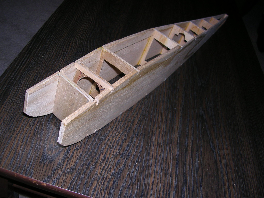
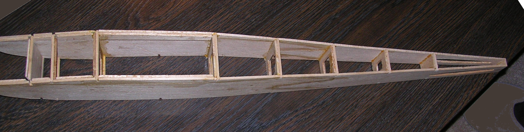
Started the bell crank installation.
The top runner (bottom in the pic) is two pieces of 1/8" lite ply laminated. It ties into the two bulk heads at either end. It is glued to the fuse doubler full length and also part of the fuse top block. It ain't going no wheres. I drilled a pivot rod hole and put a brass sleeve in that, and then put a small birch ply cap on the top over the hole to stop the rod from going all the way through. And as I am typing this I realized that the birch ply rod stop is not needed at all.
There is another lite runner runs full length between the bulk heads also. One more support is glued vertically between these two runners.
These three pieces will bear 100% of the side load from the bell crank.
The bell crank has a brass tube (pivot tube?) glued in it's pivot hole. Then there is another Piece of brass inside the pivot tube as sleeve bearing. I then have a Piano wire pivot rod through all of this. One wheel collar at the top of the rod, with enough of the rod exposed to go into the top runner brass tube.
A light ply with another brass tube slips over the bottom half of the pivot rod and is screwed to the bottom runner.
So the bell crank is very secure in the plane and is extremely free in rotation. There is not the slightest amount wobble or play in the bell crank.
And the bell crank can be removed for service, and inspection or to change things on it.
Ken
01-22-2014 | 09:11 PM
#105
Thread Starter
Built up the carbon push rod.
After some fussing a triple checking cut a slot in the outboard fuse side for the exit. I installed a 2-56 Swivel Ball Link on the bell crank. Screwed the push rod into the Swivel Ball Link. Then i noticed the assembly felt stiff. What the heck. Fussed with it some, but still stiff. removed the bottom bell crank ply mount plate thing that maybe there was a misalignment. Stinking thing is still stiff. Long story short I had a bad Swivel Ball Link. When I took it out, it was very noticeably stiff.
Go figure.
Replaced and it is super smooth and free.
It had me scratching my head for a little bit though.
Ken
01-23-2014 | 06:44 PM
#106

Love the lightweight fiberglass bellcrank, Ken. Your bipe is coming right along, looks really good.
01-23-2014 | 07:14 PM
#107
Thread Starter
Better than fiber glass .. CARBON FIBER. Some strong stuff that plate. But tough to work. I did not really want to make a lot of carbon dust , so I worked it with a hack saw blade. Wore the blade out

Ken
01-26-2014 | 12:11 PM
#108
Thread Starter
Pain levels from the surgery are down far enough that I have been able to work on the plane yesterday. 
Working on the controls, both elevator and throttle.
I temporarily hinged the elevator on with with some strip monocoat hinges. Hooked the push rod up and did a bit more trimming on the exit. The controls are super free. That is what I am aiming for when finished.
I am also starting the throttle install. The servo is done. I want the Rx bind light to be visible. I am going to put the Rx and switch in the cockpit area.
ken
01-26-2014 | 12:13 PM
#109
Thread Starter
Still fussing with the radio install for 2.4ghz throttle control.
What I thought was a lot of room for such a little radio system I have found to be other wise once the bell crank and push rod went in.
The switch is very easy to access on the outside. Very convenient. And ion the inside it is stuffed into the back corner.
The Rx is is glued to some rc 1/4" foam on ones side only, and then the foam is glued to the fuse side. I think it is pretty secure. I did the same thing with the voltage regulator. It's heat sink aluminum plate is exposed to air so should not overheat.
I am still thinking and trial fitting the placement of the wires and antenna to keep them clear of all the moving parts to ovoid jamming something and also avoid chaffing of a wire or the antenna.
The battery is a Li-Po, and has to be removed to be safely charged. There have been way to many fires and burned structures because of not isolating them during charge. I will not make that mistake.
Finding a place to stick the battery securely and have it easily removable for charging is being a challenge to say the least.
Ken
01-26-2014 | 02:04 PM
#110
Thread Starter
The radio install for the throttle control is in .. I think.
Velcro is my friend. All the wires are held down with Velcro. I glued a piece to the top plate and then a matching piece of the opposite part holds the wires in place. The voltage regulator was a bit of a pain in the _ss because it has a ferite doughnut on the Rx lead with the Rx power lead looped around it. A bulking affair with a short lead. But it is held down also. I sure do not want it getting loose and finding it's way into the bell crank area. I may revisit it again to had a backup hold down to it.
The battery is as much a pain in the butt as I thought it would be. I glued a piece of 1/4" RC foam to the bell crank bottom plate just inside of the screws. I then glued some velcro to that and strapped the battery down with the velcro. That just did not seem secure enough to me, so I added another piece of foam on the bottom between the wing and battery strap. With the wing on there is now a compression fit for the battery. I might revisit the battery and make a foam lined box for it instead.
I also installed the throttle cable.
So unless I decide to redo something the radio is in and done.
I am thinking it is time to get back to the struts and add the fairings.
Ken
01-28-2014 | 06:31 PM
#111
Thread Starter
Just started spending some time working on the plane today.
Sunday evening I made 2 false starts at making the strut fairings. Batting zip so far. That's OK, I got a bit ahead of myself anyway. So took a pause.
I am working on what has to be done before the fairings, warping the ends of the strut carbon fiber rods. They are cheaply made. The carbon strands are not wound, just strait from end to end. I found that out when cutting them. I suspected that from the start. That is OK they are really strong except to splitting. If they carbon strands were wound they would not be subject to splitting.
To resolve the possibility of the ends spitting out where the 4-40 rods enter, I am winding 203 test Spectra fishing line around the ends .. oh maybe 3/4" to 1" from the end of the carbon rods.
A bit of a frustrating and tedious chore, but I feel absolutely necessary. It would have been much, much easier to wrap the ends after the carbon rods were cut to size, but before gluing the 4-40 rods into the ends. I had planned to warp the carbon rods the whole time. It just never accrued to me to do it before gluing up the struts.
Oh well. I am still able to wrap the carbon rod ends. Just takes effort. I start with a wrap and single knot on the 4-40 rod just above the carbon rod. I lock that with with thin super glue. I finally figured out how to clamp just part of the strut assembly to my work surface and with two hands going at it to get a good wrap on the carbon rod ends. I then hit the wrap with thin super glue and cut the excess Spectra line. Then work the whole wrap with thin super glue.
6 ends down, about a hour of work. Only 18 more to go. Heck I am almost there ..not.
Ken
01-30-2014 | 09:01 PM
#112
Thread Starter
All wrapped up.
Well the struts are.
20# Spectra. One wrap. I am sure I got carried away and wrapped more of the ends than I needed to, but better more than needed than less.
Now time to make the balsa fairings to give the struts there tear drop shape., followed be the aluminum tape. And then finally at that point I can permanently mount the cabane struts.
I need some input guys. Should I tie the rudder to the throttle servo or just a fixed offset? I am at a good point to go either way.
Ken
01-31-2014 | 12:34 PM
#113
Thread Starter
More work on the struts. I am just guessing and fumbling around a bit. Sort of making it up as I go.
I cut some strips of 1/8" balsa about 3/8". Tried to sand a bevel and in about one minute said forget this BS. So just sheaved a bevel by hand with an Xacto, then a few passes with sand paper. Glued then together so as to have a inset ==< sort of shape, a V notch is the best I can describe it.
I glued this to the carbon struts. Then some carving with a SHARP Xacto, some sanding. Now I have the first one covered in spackling and drying. Then another sanding and hopefully it is good enough for the aluminum tape.
I am really anxious to get to that point and see how it looks.
I am sure hoping this works.
Ken
Last edited by flyingagin; 01-31-2014 at 12:39 PM.
01-31-2014 | 07:53 PM
#114
Yup, she's coming together, Ken, looking good. I'm part way into my 1959 Berkeley Impulse RC build.
It's a kit build out of an original kit. Back then, they didn't have the refined die cutting and laser cutting we have nowadays, which is much more accurate. It's been a challenge to get stuff to line up, still have a slight warp in the sides I will remove when I plank top and bottom. The front two bulkheads are sitting in there loosely as I need to add a landing gear, which I will have to bend from 3/32" music wire. I intend to post a separate blog about it when I make more progress.
It's a kit build out of an original kit. Back then, they didn't have the refined die cutting and laser cutting we have nowadays, which is much more accurate. It's been a challenge to get stuff to line up, still have a slight warp in the sides I will remove when I plank top and bottom. The front two bulkheads are sitting in there loosely as I need to add a landing gear, which I will have to bend from 3/32" music wire. I intend to post a separate blog about it when I make more progress.
01-31-2014 | 08:27 PM
#115
Thread Starter
Looks nice. What is the power, I think you said but I have oldtimers
I think you have enough to start a thread.
BTW I have almost all the balsa on the struts, I think just two legs left. But that means there is a lot of carving left.
Ken
I think you have enough to start a thread.
BTW I have almost all the balsa on the struts, I think just two legs left. But that means there is a lot of carving left.
Ken
01-31-2014 | 09:33 PM
#116
Power will be an Enya .09-III TV with Tatone .09-.19 Peace Pipe muffler, although I've been considering the Fuji .099S-II. The Fuji is the last of the series, where they changed the iron piston in a steel sleeve to ABC but still cross scavenged.
Regarding carving, it is one way to relax while sanding and whittling away.
Regarding carving, it is one way to relax while sanding and whittling away.
02-01-2014 | 10:27 AM
#117
Thread Starter
Either one should be nice power and it sound like the muffler should be of adequate volume George.
I have been working on the struts. Well I guess I have been working on them forever and a day.
This morning I thought I would try to cover the one that was ready for some skin. I use the aluminum tape that Bro John sent sent me.
The shine and color are just awesome, will make the struts pop out at you. Windy liked that, but then questioned the wrinkles bumps, edges. "Ken is that is how it is going to look or are you going to get it smoother"? "It is not up to your usual standards"! ......... OUCH Smiley
Well I had seen that myself, and had worked the tape, and smoothed with my finger nail, and dowels, etc. It was as good as I good get it after a rather fair amount of time and effort.
DANG IT! NUTS, CRAP, oh well strip it.
Hobby King sells Covering Film Solid Silver (5mtr) 115 for 8.25
I think I just have to wait until I order the covering film from them. I am going with small blue and white checks on the bottom sides of wings and stab. Not yet decided on the top side and fuse, but likely solids.
http://www.hobbyking.com/hobbyking/s...ardware_access...
So I got the aluminum tape off and was shock at the wight deference. Even with only 2 out of 3 legs covered the wight gain was real obvious.
John once again thanks for the tape, I really appreciated that, but I think I have to stick to normal materials.
Ken
02-03-2014 | 04:12 PM
#118
Thread Starter
I am still carving strut fairings to shape. And at the same time I am starting the engine cowling. I had to figure out how it is going to mount first.
I thought it might possibly be useful when I first stated framing up the fuse if I left a solid lip in front of the firewall .. it is. Screwing through the lip into a piece of ply mounted to the inside of the lip will serve as an excellent mount for my cowl. I will do the same on the other side allowing for the engine cylinder. Not sure on that last bit yet.
So I am working two different areas because I run out of tolerance for carving the struts and I can bounce back to the struts while waiting for glue to dry as I build up cowl blocks to carve.
Ken
02-03-2014 | 04:16 PM
#119
Thread Starter
First I got my stables out today. A lot more comfortable now. The car seat does not press on them while driving. And I can now dispense with sponge baths. The wounds look good according to the intern who removed them. Still a bit red and bruised.
Now back to our regular programming.
I have been working on the engine cowling, and the struts. Sometimes switching from one to the other while glue dried, or when I got bored with one.
I am roughing out the cowl, cutting bigger blocks on the band saw. I have been using Tightbond and the double glue method to join pieces. Takes longer, but is lighter that epoxy, and easier to carve.
Still plenty of more fill blocks. On the exhaust side I will likely use a couple of small removable blocks. Behind the engine I will just glue a shaped block to fill things in.
I will do some carving on the outside. to get the shape close and then hollow out the inside.
Ken
02-04-2014 | 05:07 PM
#120
Thread Starter
Roughing in the cowl. I have added a bunch of fill to the inside, so as to have something to work with. I opened up cut out as much as I had to, to get the cowl on and off in one piece.
I placed a 2.5" spinner on the engine. Thought that looked good and allowed for an 11-4 prop. That should keep the speed reasonable at full song.
Roughed out some lines and sanded down very roughly with my belt sander. Now I am removing most of the material I added to the cowl. Using a ball mill in my Dremel to remove inner material. There is a lot of wood to get rid of. That will get the weight out of the cowl.
There are a bunch of odds and ends and some corrections to do at this time. I am just sort of bouncing around from one thing to another to get a better ideal of how she is going to look, and not paint myself into too much of a corner.
Ken
02-04-2014 | 05:11 PM
#121
Thread Starter
More work on the cowl. Some smoothing and more shaping towards final shape, AND MAKING A HOLE. WHOOPS!! hahaha
I removed a lot of the inside excess with a ball mill, a round gouge, and believe it or not a pair of 6" Dykes. I was able to clip and pull chunks of wood out with the Dykes, and I was also very successful at making the hole in the top of the cowl with them. Jeez. it will fill easy enough.
I then smoothed the inside with a sanding drum, and the outside with a coarse then medium foam sanding block.
I should have glued a light ply nose ring to the front of the cowl. But I will true the front up tomorrow and the glue the ply ring onto the front.
All in all, I did not have to do much carving with a knife.
Ken
02-05-2014 | 08:34 PM
#122
Nice work, Ken and regarding oops! I've used a covering iron over a wetted area to bring out dents, synthetic spackling compound to fill dents; sometimes even glue a piece of balsa over the bad and reshape. A good job isn't so much that one did a perfect job of contouring and sanding, but they are able also to repair blemishes to hide them.
02-05-2014 | 08:46 PM
#123
Thread Starter
Nice work, Ken and regarding oops! I've used a covering iron over a wetted area to bring out dents, synthetic spackling compound to fill dents; sometimes even glue a piece of balsa over the bad and reshape. A good job isn't so much that one did a perfect job of contouring and sanding, but they are able also to repair blemishes to hide them.
I will still be removing some more material from inside of the cowl. It will eventually have some light glass applied to the inside.
I just realized I still have to carve wingtips.
Ken
02-06-2014 | 11:12 AM
#124
Regarding wing tips, I've found that a block sander with really rough grit, say 80 then transitioning to 150, 300, etc. does a gentler job than sawing and gouging. However one must be prepared to do this in say the garage or outside due to the sanding dust plus weather a dust mask, which may be difficult in the colder weather or if one has balsa wood allergies. 
02-06-2014 | 12:37 PM
#125
Thread Starter
Regarding wing tips, I've found that a block sander with really rough grit, say 80 then transitioning to 150, 300, etc. does a gentler job than sawing and gouging. However one must be prepared to do this in say the garage or outside due to the sanding dust plus weather a dust mask, which may be difficult in the colder weather or if one has balsa wood allergies.
I will set my disk/belt sander up outside on a chair and park my fat back end in another, and have at it. WITH A DUST MASK ON. I keep a mask outside in the storage closet on the porch as well as one hanging above my build desk.
A balsa dust induce asthma attack taught me my lesson real good.
Right now it is a bit to cold for my taste outside though. Wait a few days and it will be nice.
Outside on the enclosed porch is where I painted the plane in my avatar.
Ken

