


Aeroworks 50CC Mustang Rebuild
 12-04-2013, 06:14 PM
#1

Thread Starter
My Feedback: (34)

Join Date: Mar 2002
Location: New Hill, NC
Posts: 230
Likes: 0
Received 0 Likes
on
0 Posts
I picked up this Mustang from a flier in North Carolina after it had suffered a wing mounting dowel failure. The fuselage bore the brunt of the damage. Wing is in good condition except for the trailing edge where the mounting bolts were located. I traced out all of the parts that I could and will cut them out of the wood that just arrived today.
Here is how she looked after the crash...


I made templates of the formers, servo and equipment mounting trays and of the "good" fuselage side so I can cut new parts for those that were obliterated in the crash.


My wood order arrived today from National Balsa, took them a while to get it to me but the quality looks good for the 1/8" Balsa and lite ply. Also had them ship some triangle stock and 1/8" dowel for reinforcing the rebuilt motor box.

Since I had some free time, I went ahead and started cutting out the replacement fuselage side and motor box parts from the 1/8" ply. I still need to cut out the right side for the motor box, it is a duplicate of the left just being a tad shorter to account for the built in engine thrust. Lightening holes still need to be cut out as well.

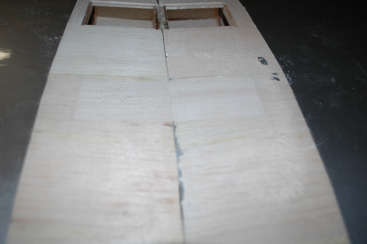
I had previously been working on the wing and here are a couple of closeups of the damage done the trailing edge where the bolts ripped out. I will cut the damaged area out and splice in some new hardwood that will be tied into the remaining hardwood block. Once everything is repaired, the top of the wing will be fiberglassed.


This pic shows where I cut out the damaged areas and the new hardwood blocks that I have cut to shape to match the wing profile.


When the wing departed the fuselage, the servo wires and air lines damaged some of the sheeting. I have removed the damaged areas and will replace.


And that is pretty much where I am at right now. I have ordered a new cowling, canopy, cockpit kit and radiator scoop from Aeroworks. I will need to wait until that stuff arrives so I can use the cowling to get the outline for the formers that turned to dust in the crash. The fiberglass wing fillets are pretty messed up as well, but they are not available as replacement parts so I will probably need to go the evercoat route and make them myself.
Here is how she looked after the crash...
I made templates of the formers, servo and equipment mounting trays and of the "good" fuselage side so I can cut new parts for those that were obliterated in the crash.
My wood order arrived today from National Balsa, took them a while to get it to me but the quality looks good for the 1/8" Balsa and lite ply. Also had them ship some triangle stock and 1/8" dowel for reinforcing the rebuilt motor box.
Since I had some free time, I went ahead and started cutting out the replacement fuselage side and motor box parts from the 1/8" ply. I still need to cut out the right side for the motor box, it is a duplicate of the left just being a tad shorter to account for the built in engine thrust. Lightening holes still need to be cut out as well.
I had previously been working on the wing and here are a couple of closeups of the damage done the trailing edge where the bolts ripped out. I will cut the damaged area out and splice in some new hardwood that will be tied into the remaining hardwood block. Once everything is repaired, the top of the wing will be fiberglassed.
This pic shows where I cut out the damaged areas and the new hardwood blocks that I have cut to shape to match the wing profile.
When the wing departed the fuselage, the servo wires and air lines damaged some of the sheeting. I have removed the damaged areas and will replace.
And that is pretty much where I am at right now. I have ordered a new cowling, canopy, cockpit kit and radiator scoop from Aeroworks. I will need to wait until that stuff arrives so I can use the cowling to get the outline for the formers that turned to dust in the crash. The fiberglass wing fillets are pretty messed up as well, but they are not available as replacement parts so I will probably need to go the evercoat route and make them myself.

 12-05-2013, 07:03 AM
#3

Same with me, I am interested in the process too. We can all take lessons in reconstruction techniques. Although I have built in the past, I am tending toward the ARF types now. Rebuilding a crashed plane is a good way to keep in practice. Well not that I crash a lot......
 12-05-2013, 06:06 PM
#5
Thread Starter
My Feedback: (34)
Join Date: Mar 2002
Location: New Hill, NC
Posts: 230
Likes: 0
Received 0 Likes
on
0 Posts
I was able to get a little more done this afternoon after work. I finished cutting out all of the lightening and tab holes on the replacement ply parts. I am reusing the firewall as it was not damaged from the crash and it is already drilled for the engine that I will be using, which is a DLE 55. You will notice the dremel with a drill bit, I used this to widen the slot holes in the motor box sides as I was test fitting it together.

Test fitting the motor box pieces together...

Motor box assembled dry, not a bad fit. All of the inside corners will have triangle stock and the firewall will be pinned when I get around to gluing it all together.

With the motor box looking pretty good, I set it aside and turned my attention to the fuselage. The front of the left fuselage side looks a little rough as the picture shows. I will replace the broken parts and probably back it on the inside with 1/16 ply. The outside will be sheeted with 1/8 balsa. Second picture shows the new plywood piece that will take the place of the damaged section and the third picture shows the new piece laying over top of the damaged section.


I then mocked up the new right fuselage side to see how things lined up. The sheeting that is on the side that is still present will be cut back to the line as noted by the marker. This will allow the new 1/8" sheeting that will be applied to the fuselage side to be staggered and add strength. I will use some fiberglass cloth over this joint prior to applying the new sheeting. Triangle stock will be added to the inside joint at this former for additional strength.

That is it for tonight. There are still a couple of formers that need to be cut, but those are waiting on the cowl to arrive so I can get the correct radius. Those formers did not survive the crash.
Test fitting the motor box pieces together...
Motor box assembled dry, not a bad fit. All of the inside corners will have triangle stock and the firewall will be pinned when I get around to gluing it all together.
With the motor box looking pretty good, I set it aside and turned my attention to the fuselage. The front of the left fuselage side looks a little rough as the picture shows. I will replace the broken parts and probably back it on the inside with 1/16 ply. The outside will be sheeted with 1/8 balsa. Second picture shows the new plywood piece that will take the place of the damaged section and the third picture shows the new piece laying over top of the damaged section.
I then mocked up the new right fuselage side to see how things lined up. The sheeting that is on the side that is still present will be cut back to the line as noted by the marker. This will allow the new 1/8" sheeting that will be applied to the fuselage side to be staggered and add strength. I will use some fiberglass cloth over this joint prior to applying the new sheeting. Triangle stock will be added to the inside joint at this former for additional strength.
That is it for tonight. There are still a couple of formers that need to be cut, but those are waiting on the cowl to arrive so I can get the correct radius. Those formers did not survive the crash.
12-06-2013, 07:56 PM
#6
Thread Starter
My Feedback: (34)
Join Date: Mar 2002
Location: New Hill, NC
Posts: 230
Likes: 0
Received 0 Likes
on
0 Posts
While I am waiting on the parts from Aeroworks, I decided to do some work on the wing.
I started by replacing the damaged sheeting on the center section by putting some 1/8" balsa as a lip so that the new sheeting would have something to glue to.

I then cut and fitted the new sheeting. Filler will be applied to any gaps present, final sanded and then fiberglass cloth applied. I will then use a forstner bit to drill the holes to allow the air lines and servo extensions to pass through.

It was then time to turn my attention to replacing the trailing edge that was damaged by the wing bolts. The original trailing edge wing mount was not actually hardwood, but really dense balsa sandwiched by the balsa sheeting. I am replacing this with hardwood that will be tied into the existing structure with 1/4" carbon fiber rods. Gorilla glue is used and after it has set, I will cut and frame out the necessary pieces to square off the trailing edge. The damaged parts are a good source for these pieces.. :-) First picture is of the carbon fiber rods, second is my "depth gauge" on the drill. I drilled two holes in both the trailing edge and hardwood block and liberally applied Gorilla glue and the third picture shows the block attached with just a hint of the glue foaming. Once all of the pieces are attached, filled, and sanded, I will apply fiberglass cloth for added strength.


That is it for tonight...
I started by replacing the damaged sheeting on the center section by putting some 1/8" balsa as a lip so that the new sheeting would have something to glue to.
I then cut and fitted the new sheeting. Filler will be applied to any gaps present, final sanded and then fiberglass cloth applied. I will then use a forstner bit to drill the holes to allow the air lines and servo extensions to pass through.
It was then time to turn my attention to replacing the trailing edge that was damaged by the wing bolts. The original trailing edge wing mount was not actually hardwood, but really dense balsa sandwiched by the balsa sheeting. I am replacing this with hardwood that will be tied into the existing structure with 1/4" carbon fiber rods. Gorilla glue is used and after it has set, I will cut and frame out the necessary pieces to square off the trailing edge. The damaged parts are a good source for these pieces.. :-) First picture is of the carbon fiber rods, second is my "depth gauge" on the drill. I drilled two holes in both the trailing edge and hardwood block and liberally applied Gorilla glue and the third picture shows the block attached with just a hint of the glue foaming. Once all of the pieces are attached, filled, and sanded, I will apply fiberglass cloth for added strength.
That is it for tonight...
12-08-2013, 09:45 AM
#7
Thread Starter
My Feedback: (34)
Join Date: Mar 2002
Location: New Hill, NC
Posts: 230
Likes: 0
Received 0 Likes
on
0 Posts
Decided to do a little more work on the Mustang as it is a rainy and cold day here in North Carolina...
First thing I did was cut out the replacement cowling mounting tabs, there are six of these tabs needed.

I then decided to replace the damaged front section on the left fuselage side. First photo shows where I marked the damaged area to be cut off. I used a dremel with a cut off wheel. Second photo shows me hold the replacement piece from behind the side to mark where it would need to be cut. Third photo shows the 1/16" ply doubler to go over the joint and the fourth photo shows the repaired piece.


The repaired left front fuselage side.

As you can see, I have attached the replacement right side. The top of that side is 1/16" lower than the left because someone did not measure the wood on the left side correctly! The balsa stick on the left side is 1/4 x 5/16 and the replacement balsa stick that I ordered is 1/4 x 1/4. I will just have to sand the left side down a 1/16" so everything matches.
Now, just waiting on the stuff from Aeroworks arrive on Wednesday so I can get the dimensions from the cowl to cut out the two remaining formers that turned into dust from the crash.
The replacement wing hold block is looking good, nice and strong. Needs a few pieces of balsa to build out the length on the trailing edge to match up to the fuselage. Pictures on that next time.
First thing I did was cut out the replacement cowling mounting tabs, there are six of these tabs needed.
I then decided to replace the damaged front section on the left fuselage side. First photo shows where I marked the damaged area to be cut off. I used a dremel with a cut off wheel. Second photo shows me hold the replacement piece from behind the side to mark where it would need to be cut. Third photo shows the 1/16" ply doubler to go over the joint and the fourth photo shows the repaired piece.
The repaired left front fuselage side.
As you can see, I have attached the replacement right side. The top of that side is 1/16" lower than the left because someone did not measure the wood on the left side correctly! The balsa stick on the left side is 1/4 x 5/16 and the replacement balsa stick that I ordered is 1/4 x 1/4. I will just have to sand the left side down a 1/16" so everything matches.
Now, just waiting on the stuff from Aeroworks arrive on Wednesday so I can get the dimensions from the cowl to cut out the two remaining formers that turned into dust from the crash.
The replacement wing hold block is looking good, nice and strong. Needs a few pieces of balsa to build out the length on the trailing edge to match up to the fuselage. Pictures on that next time.
12-08-2013, 09:48 AM
#8
Thread Starter
My Feedback: (34)
Join Date: Mar 2002
Location: New Hill, NC
Posts: 230
Likes: 0
Received 0 Likes
on
0 Posts
Decided to do a little more work on the Mustang as it is a rainy and cold day here in North Carolina...
First thing I did was cut out the replacement cowling mounting tabs, there are six of these tabs needed.
I then decided to replace the damaged front section on the left fuselage side. First photo shows where I marked the damaged area to be cut off. I used a dremel with a cut off wheel. Second photo shows me hold the replacement piece from behind the side to mark where it would need to be cut. Third photo shows the 1/16" ply doubler to go over the joint and the fourth photo shows the repaired piece.
The repaired left front fuselage side.
As you can see, I have attached the replacement right side. The top of that side is 1/16" lower than the left because someone did not measure the wood on the left side correctly! The balsa stick on the left side is 1/4 x 5/16 and the replacement balsa stick that I ordered is 1/4 x 1/4. I will just have to sand the left side down a 1/16" so everything matches.
Now, just waiting on the stuff from Aeroworks to arrive on Wednesday so I can get the dimensions from the cowl to cut out the two remaining formers that turned into dust from the crash.
The replacement wing hold block is looking good, nice and strong. Needs a few pieces of balsa to build out the length on the trailing edge to match up to the fuselage. Pictures on that next time.
 12-08-2013, 05:08 PM
#11
Thread Starter
My Feedback: (34)
Join Date: Mar 2002
Location: New Hill, NC
Posts: 230
Likes: 0
Received 0 Likes
on
0 Posts
Hey Scott,
I am going to stick with Ultracote for this one. I don't have the space and equipment to do glass and a paint job. Scheme is going to be Petie 3rd. I'm taking inspiration from Tom Bell's Mustang in the second picture on what can be done with Ultracote, panel lines, rivets, and airbrushed weathering.
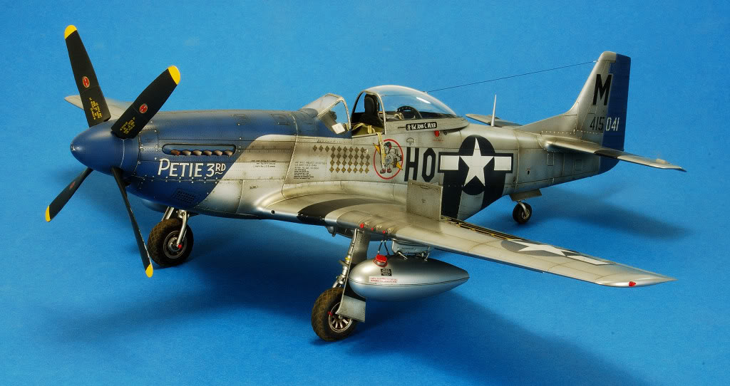

I am going to stick with Ultracote for this one. I don't have the space and equipment to do glass and a paint job. Scheme is going to be Petie 3rd. I'm taking inspiration from Tom Bell's Mustang in the second picture on what can be done with Ultracote, panel lines, rivets, and airbrushed weathering.
12-10-2013, 06:44 PM
#12
Thread Starter
My Feedback: (34)
Join Date: Mar 2002
Location: New Hill, NC
Posts: 230
Likes: 0
Received 0 Likes
on
0 Posts
Cowling, canopy, cockpit and radiator scoop arrived today.


Inside of the cowling was a nice piece of cardboard which I used to make the template to cut out the former that ties the motor box to the fuselage sides. Note -- the inside of the cardboard was not precut, I measured the motor box that I had cut out previously and then cut it out.

The former fitted to the motor box

The new motor box and former mocked up on the fuselage.


At this point I flipped the fuselage over and set the wing in the saddle in order to get the proper profile for the front wing hold down former. I will add a sub-former on each of these formers that are recessed 1/8" and notched to accept 1/4" square stock. That will then be sheeted.

Making good progress....
Inside of the cowling was a nice piece of cardboard which I used to make the template to cut out the former that ties the motor box to the fuselage sides. Note -- the inside of the cardboard was not precut, I measured the motor box that I had cut out previously and then cut it out.
The former fitted to the motor box
The new motor box and former mocked up on the fuselage.
At this point I flipped the fuselage over and set the wing in the saddle in order to get the proper profile for the front wing hold down former. I will add a sub-former on each of these formers that are recessed 1/8" and notched to accept 1/4" square stock. That will then be sheeted.
Making good progress....
12-11-2013, 05:55 AM
#13
Making good progress....
I think you are understating your progress... To me it looks that amazing progress. I would still be trying to figure out where to start. Very very good work.
I think you are understating your progress... To me it looks that amazing progress. I would still be trying to figure out where to start. Very very good work.
12-11-2013, 06:42 AM
#14
Thread Starter
My Feedback: (34)
Join Date: Mar 2002
Location: New Hill, NC
Posts: 230
Likes: 0
Received 0 Likes
on
0 Posts
Thanks -- it has taken a lot of thinking and looking at pictures of assembled Aeroworks Mustangs to try and see how everything was originally was put together. I think I have a pretty good grasp on how it should go back together. Just takes a lot of template making, fitting and trimming to get things to fit correctly.
12-14-2013, 02:18 PM
#15
Thread Starter
My Feedback: (34)
Join Date: Mar 2002
Location: New Hill, NC
Posts: 230
Likes: 0
Received 0 Likes
on
0 Posts
Progress continues, although at a little slower pace. It is a bit chilly in the garage! Anyway, I have attached the interior former to the back of the motor box and test fitted into the fuselage as shown in the pictures below.


I glued in the doublers and notched them for the 1/4" x 1/4" square stock that the bottom sheeting will go over.

I then flipped everything over and set the canopy and windshield in place so that I could get the proper height of the former that is needed to provide support for the windshield.

I have not glued the new motor box to the fuselage yet as I still have some reinforcing to do with triangle stock on the corners. I ran out of triangle stock, so I will have to pick up some more. Also need some more 1/4" square stock for the top stringers that will run from the windshield to the firewall former. This last picture shows how everything is coming together.

Until next time...
I glued in the doublers and notched them for the 1/4" x 1/4" square stock that the bottom sheeting will go over.
I then flipped everything over and set the canopy and windshield in place so that I could get the proper height of the former that is needed to provide support for the windshield.
I have not glued the new motor box to the fuselage yet as I still have some reinforcing to do with triangle stock on the corners. I ran out of triangle stock, so I will have to pick up some more. Also need some more 1/4" square stock for the top stringers that will run from the windshield to the firewall former. This last picture shows how everything is coming together.
Until next time...
12-15-2013, 04:05 PM
#16
Thread Starter
My Feedback: (34)
Join Date: Mar 2002
Location: New Hill, NC
Posts: 230
Likes: 0
Received 0 Likes
on
0 Posts
Anyone out there?...
Did a little more work today on the cockpit area rebuilding the sides that were missing. From the pictures of the windshield that I have seen I am not that excited with the factory method of the windshield mounting on top of the sheeting. I am going to try and have the windshield to be flush with the surrounding sheeting.
This pic shows how the factory method has the windshield mounting on top of the sheeting... do not like.

Canopy rails have been mocked up and tack glued in place. Cockpit sides and instrument panel test fit.


Just had to get a picture with the cowling in place. It is starting to look like a P-51 again.


Did a little more work today on the cockpit area rebuilding the sides that were missing. From the pictures of the windshield that I have seen I am not that excited with the factory method of the windshield mounting on top of the sheeting. I am going to try and have the windshield to be flush with the surrounding sheeting.
This pic shows how the factory method has the windshield mounting on top of the sheeting... do not like.
Canopy rails have been mocked up and tack glued in place. Cockpit sides and instrument panel test fit.
Just had to get a picture with the cowling in place. It is starting to look like a P-51 again.
12-16-2013, 03:29 PM
#17
Thread Starter
My Feedback: (34)
Join Date: Mar 2002
Location: New Hill, NC
Posts: 230
Likes: 0
Received 0 Likes
on
0 Posts
Some inspiration shots...


I installed the cowling mounting tabs today and now I am just waiting on fiberglass cloth and more triangle and square stock. Once I have that, I can permanently glue the motor box to the fuselage and work on sheeting the fuselage.
I installed the cowling mounting tabs today and now I am just waiting on fiberglass cloth and more triangle and square stock. Once I have that, I can permanently glue the motor box to the fuselage and work on sheeting the fuselage.
12-16-2013, 06:12 PM
#18
Very very nice. From where it started, you have done a masterful job of reconstruction. It may have already been covered, but did you improve the wing attachment method? After all, it's what caused the problems in the first place.
12-16-2013, 06:49 PM
#19
Thread Starter
My Feedback: (34)
Join Date: Mar 2002
Location: New Hill, NC
Posts: 230
Likes: 0
Received 0 Likes
on
0 Posts
I don't plan on redesigning the front hold down method as it will work perfectly fine as designed as long as there is some glue on the dowels to prevent them from slipping back into the wing. ") I was surprised that the wings did not have an internal stop built in to prevent the dowels from sliding back into the wing??
I was surprised that the wings did not have an internal stop built in to prevent the dowels from sliding back into the wing??
This pic shows how the wing dowels were when I obtained the airplane. One was completely missing and the other is almost flush with the front of the wing.

I was surprised that the wings did not have an internal stop built in to prevent the dowels from sliding back into the wing?? This pic shows how the wing dowels were when I obtained the airplane. One was completely missing and the other is almost flush with the front of the wing.
12-16-2013, 07:57 PM
#20

ctshepard you are doing a great job, I have done a few rebuilds myself and I think you are not shy about hard work ! One thing I would have suggested if I had been there and seen what you are doing. I don't know if that airframe will need any nose weight? but I think I would have been tempted to cut two new front sides from lite ply, and not even drilled any lightening holes in them. I think you could have made it stronger , easier, and barely heavier. I guarantee it would still fly well. This is in NO WAY meant as a criticism, it is just another route that might have been easier with no bad effects.
Keep up the good work it is obvious you have a good hand on construction, I will be happy to see that bird in the air ! I am actually trying to repair an abandoned Nosen P51 at the moment. I have yet to pick a paint scheme, I like the one you are going with...
Keep up the good work it is obvious you have a good hand on construction, I will be happy to see that bird in the air ! I am actually trying to repair an abandoned Nosen P51 at the moment. I have yet to pick a paint scheme, I like the one you are going with...
12-17-2013, 02:56 PM
#21
Thread Starter
My Feedback: (34)
Join Date: Mar 2002
Location: New Hill, NC
Posts: 230
Likes: 0
Received 0 Likes
on
0 Posts
Foodstick, thanks for the reply. I won't know if the airframe will need nose weight until I get everything back together and engine mounted, etc. Planning on picking up some more materials in the next couple of days to continue work on it.
12-21-2013, 06:03 PM
#22
Thread Starter
My Feedback: (34)
Join Date: Mar 2002
Location: New Hill, NC
Posts: 230
Likes: 0
Received 0 Likes
on
0 Posts
Continuing work on the Mustang... I've got the top stringers and air tank former in place. Started fitting the sheeting on the left side of the fuselage. Coming along nicely.


12-22-2013, 08:41 AM
#24
Thread Starter
My Feedback: (34)
Join Date: Mar 2002
Location: New Hill, NC
Posts: 230
Likes: 0
Received 0 Likes
on
0 Posts
The binder clips will leave impressions on soft balsa. The top sheeting that I used is very hard. Clamps are in very short supply in my shop. I need to stop at a Northern Tool or Harbor Freight and stock up.