


Everything Radial Engines

 01-28-2021, 07:58 AM
#3827

I have just bought a Saito FA-325R5 D which I want to install in a scale model. The problem I have is that the engine outside diameter is too small for scale. I am thinking about raising the cylinders 1" by using machined spacers. This will of course require machining a new master rod, slave rods, pushrods and adjusting the length of the pushrod tubes and intake tubes.
I know that it quite an undertaking but - apart from that, is there any negative impact some of you guys can think of that should keep me from doing this?
Thanks for any advice offered.
Joshua
I know that it quite an undertaking but - apart from that, is there any negative impact some of you guys can think of that should keep me from doing this?
Thanks for any advice offered.
Joshua
I admire your ambition, but FORGET about this idea. It will never work.
One of MANY problems you will encounter is rod length and resultant rod ratio, which will be totally out of kilter.
At the base of the cylinders, the longer rods will interfere.
This simply won't work.
IF you don't wish to purchase a much larger 5 cylinder OR downsize the airframe, here is an easy idea:
Since you will need cylinder baffling anyway, why not build a scale DUMMY 5 cylinder radial to install in front of your Saito that will also act as an intake air cooling baffle?
Of course, if your aircraft features an exposed 5 cylinder, then this idea won't work either.
There are much larger 5 cylinder radials available...

 01-28-2021, 06:34 PM
#3831

My Feedback: (66)
Joshua,
I admire your ambition, but FORGET about this idea. It will never work.
One of MANY problems you will encounter is rod length and resultant rod ratio, which will be totally out of kilter.
At the base of the cylinders, the longer rods will interfere.
This simply won't work.
IF you don't wish to purchase a much larger 5 cylinder OR downsize the airframe, here is an easy idea:
Since you will need cylinder baffling anyway, why not build a scale DUMMY 5 cylinder radial to install in front of your Saito that will also act as an intake air cooling baffle?
Of course, if your aircraft features an exposed 5 cylinder, then this idea won't work either.
There are much larger 5 cylinder radials available...
2. "At the base of the cylinders, the longer rods will interfere." - That is the only concern I have but I will model it to find out.
3. "MANY problems" - Can you name at least 3?
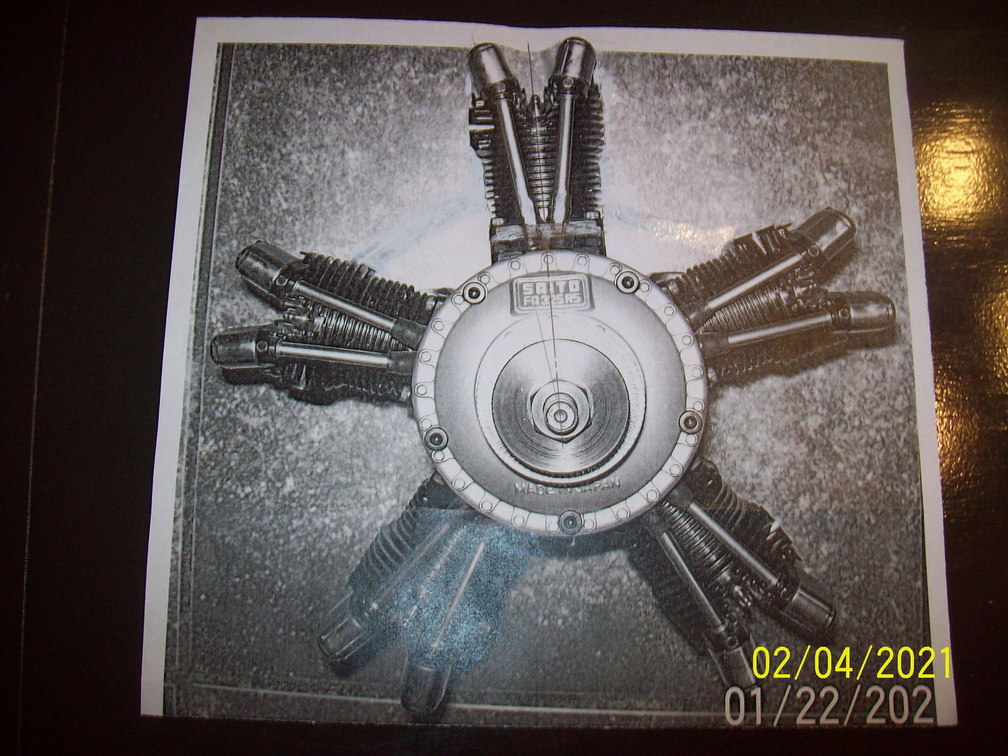
There is something most of those who commented so far misunderstand: There is NO radial on the hobby market that remotely come close to scale diameter and has adequate power. Power wise - the Saito is all I need for my 1/4 scale Kinner Sportwing project. The original was powered by a Kinner K-2 or B-2, both roughly 44" diameter. At 1/4 scale this would be 11". The Saito is 8.6". To get an 11" radial I will need something like the UMS 5-260 CC which weighs 12 Lbs. and could fly a 1/2 scale Sportwing at 1/3 throttle. The $3,100 price tag is another story altogether.
https://ch-ignitions.com/product/ums...-specification
01-30-2021, 05:58 AM
#3832
Join Date: Jun 2006
Location: Reggio Emilia, ITALY
Posts: 107
Likes: 0
Received 0 Likes
on
0 Posts
I have just bought a Saito FA-325R5 D which I want to install in a scale model. The problem I have is that the engine outside diameter is too small for scale. I am thinking about raising the cylinders 1" by using machined spacers. This will of course require machining a new master rod, slave rods, pushrods and adjusting the length of the pushrod tubes and intake tubes.
I know that it quite an undertaking but - apart from that, is there any negative impact some of you guys can think of that should keep me from doing this?
Thanks for any advice offered.
Joshua
I know that it quite an undertaking but - apart from that, is there any negative impact some of you guys can think of that should keep me from doing this?
Thanks for any advice offered.
Joshua
If you make the rods 1" longer, they become heavier, sure. But that's not the end to it: longer rods are more likely to buckle in compression, so they have to be built stronger, likely adding even more material.
This will make the whole rotating assembly far too heavy for the standard counterweight, which means lots of vibrations. Unless you enlarge the crankshaft counterweight too, but that's yet another piece to machine. Also, what if a suitably heavy counterweight doesn't fit in the crankcase (unlikely, but not impossible)?
Even if the counterweight is changed to compensate the added mass, there will still be increased pressure through the connecting rods big ends. This added pressure could cause the lubricant film to fail, leading to seizure. That is if the big ends don't just let go due to the increased forces.
Also, does the FA-325R5 use a needle bearing in the master rod big end? If so, it is strong enough for the added forces? A switch to a bushing may be required, but how to properly lubricate it?
As for the valvetrain, I have serious doubts about making the pushrods 1" longer. Will they buckle? I don't know. Perhaps they will need to be a larger diameter.
And, again, their increased weight (due to length and, possibly, diameter increase) could be an issue, this time resulting in valve float at high RPM.
An alternative would be to relocate the camshafts 1" out, thus allowing to use all the original valvetrain components. But then an enlarged crankcase is in order, together with some more idler gears to connect the relocated camshafts with the crank gear.
Would all this run? Maybe.
Would it run well? I highly doubt it. And it could end up not having enough power to fly the plane, while being a lot heavier than the already-not-so-featherweight stock FA-325R5.
I suggest another approach, though: have you considered building a radial out of 5 individual single cylinder engines geared together?
You could machine a pentagonal block with mounting holes for 5 individual engines, then fit a (possibly helical cut) gear to each shaft, all meshing with a central gear to which the propeller is connected.
You could even decide to mount the individual engines facing back on the central block to have the pushrods in the back of the engine as the Kinner engines had. The issue is that you'd point the intake ports to the front. It's a tradeoff.
But you could get fancy and decide to customize the 5 individual engines. Maybe it's possible to fit a FA-200Ti rear cylinder (with side intake and exhaust ports) to a regular FA-91 crankcase and internals, obviously with the cylinder rotated so that the pushrods are on the front? I have no idea. But if possible you could then mount the whole engine backward on the pentagonal core and have rear pushrods with side intake and exhaust ports. With custom intake and exhaust manifolds you should get fairly close to the look of Kinner radials that I've seen in pictures. You would end up with a propeller spinning in the correct direction too, and at 4.5 cu.in. total displacement it should be able to fly the plane comfortably.
As a bonus you could tweak the gear sizes to give you something other than 1:1 ratio, enabling to drive even larger propellers if desired.
Last edited by Radial power; 01-30-2021 at 06:41 AM. Reason: Replaced FA-100Ti with FA-200Ti and FA-100 with FA-91
01-30-2021, 06:49 AM
#3833
My Feedback: (66)
Radial Power
Thank you very much for the in-depth treatise of the subject.
As you correctly pointed out to the possible interference of the con rods with the cylinder which I already alluded to, here are my thoughts about other parts of your analysis.
1. Increased rotating mass - I am aware of this and my thinking is that if the new master rod and articulated rods will be machined from Al. 7075 - enough material could possibly be removed from the sides of the rods for weight saving while not hurting the static moment of inertia and therefore chance of buckling. While adding 1" in length appears to be "Huge", I think that in reality it may not be so. The cylinders of this engine are all from the FA-65 single and use essentially the same cams and gears.
2. This is actually 5 independent single cylinder engines coupled thru a master and articulating rods to make a radial.
3. The pushrods in the FA-65 are made from heat treated steel, are 46 mm long, and if the longer ones are perhaps increased slightly in diameter, I doubt that they will buckle. The forces acting on the pushrods are very low. In addition, the pushrod guide tubes may also aid against the possibility of buckling. If you ever seen the pushrods on a 220 hp Continental or 275 hp Jacobs - they are about 1/4" in diameter.I do not plan on running the engine past 5000 rpm in any case so valve float is not likely to be an issue.
4. Lubrication: The Master Rod and Articulating Rods all have bronze bushings. CH Ignitions have converted several of these radials to gasoline with electronic ignition and my understanding is that they work fine. I assume that Gas/Oil mix has less lubricity than Castor Oil/Methanol mix.
5. Increased force on the crank pins? may be a tad due to reduced angularity but still - we are talking "Pocket Change" considering that each cylinder is essentially a .65 engine.
In general, I want to point out that I have several plans from home built radials that were published in the now defunct "Strictly IC" magazine. These include Merritt Zimerman plans for a Kinner K-2 replica and Forrest Edward's 5 cylinder radial. As you probably know all of those radials are Long Stroke (under square) and I doubt that the designers had access to precise analysis for determining the exact weight of the counter weight on the crankshaft. I suspect that they used a "Rule of Thumb" approach, and, the fact is that their designs worked fine. I even have a picture of a Zimerman Kinner built in the USA where rather than machine the complex cylinder head - the builder adapted a OS-160 (essentially OS-80) cylinder heads.
I plan on buying a FA-65 for experimentation with the conrod interference issue and find out whether my quest to increase the diameter is at all feasible before committing time and money to this endeavor.
Thanks again for your input.
Joshua
01-30-2021, 07:07 AM
#3834
Join Date: Jun 2006
Location: Reggio Emilia, ITALY
Posts: 107
Likes: 0
Received 0 Likes
on
0 Posts
I meant to say that if the rods assembly becomes heavier, it will generate higher centrifugal forces at the same rotational speed. This increased force has to pass "through" the crank pin before being compensated by the crank counterweight, therefore increasing the load on the pin.
But it just occurred to me that the centrifugal component may only be a minor contributor to the total crank pin load when compared to the pulses produced with each power stroke. If that is indeed the case, then yes, this increased stress may not be that important after all.
01-30-2021, 07:45 AM
#3835
1. What is "Rod Ratio"?
2. "At the base of the cylinders, the longer rods will interfere." - That is the only concern I have but I will model it to find out.
3. "MANY problems" - Can you name at least 3?
There is something most of those who commented so far misunderstand: There is NO radial on the hobby market that remotely come close to scale diameter and has adequate power. Power wise - the Saito is all I need for my 1/4 scale Kinner Sportwing project. The original was powered by a Kinner K-2 or B-2, both roughly 44" diameter. At 1/4 scale this would be 11". The Saito is 8.6". To get an 11" radial I will need something like the UMS 5-260 CC which weighs 12 Lbs. and could fly a 1/2 scale Sportwing at 1/3 throttle. The $3,100 price tag is another story altogether.
https://ch-ignitions.com/product/ums...-specification
Con Rod interference at the cylinder base may be THE ONLY problem worth worrying about, as it may be impossible to resolve.
However�
1. Fuel intake velocity: Lengthening the intakes may result in loss of atomization / fuel drop-out.
2. The increase in internal volume will result in lower vacuum, poor throttle response; possibly creating the need for a fuel pump.
3. Substantial increase in rotational inertia.
4. Lower cylinders are likely to flood more easily and/or suffer from mixture imbalance.
5. Increased pushrod length: Without stronger pushrods, they may bend or vibrate badly.
6. Unless you are machining all new LONG cylinders, adding some sort of spacer is likely to result in improper seal, lack of rigidity and distortion.
7. Machining a larger diameter crankcase, defeats the whole purpose of increasing engine diameter since a larger crankcase is very unscale.
But hey! Many inventors throughout history were told something couldn�t be done, and they did it anyway. I say GO FOR IT.
 01-31-2021, 06:54 AM
#3836
Join Date: Jun 2006
Location: Reggio Emilia, ITALY
Posts: 107
Likes: 0
Received 0 Likes
on
0 Posts
By the way, this is what I was thinking of with the suggestion at the end of my long post: five-cylinder radial engine homemade from five OS FS-70S II (scroll down a bit for some nice pictures).
I believe that the "crankcase" could be made quite a bit more compact than what shown in that thread, especially if one is willing.to machine it out of a single piece of metal rather than using a built-up design.
A bonus of this approach is that you'd end up with rear-facing pushrods and a very short engine "nose", as found in Kinner radials. Using Saito engines instead of OSes you'd get the split rocker boxes too. And using FA-100Ti / FA-200Ti rear cylinders on the 5 individual engines could move the ports to the side of the cylinders, leaving the front of the cylinders completely clean, further mimicking the Kinner look.
Food for thought.
01-31-2021, 07:58 AM
#3837
My Feedback: (66)
A friend of Mine, Mike Goldowsky produced a "Radial" like this back in the 1990s. It was made from K&B 20 or 28 Super Sportster 2 stroke engine. The problem is that if you buy 5 Four Stroke engines to build this - you already spend as much as a true radial will cost, and, with 2:1 or thereabout reduction - it will NEVER sound like a radial.
MIKE GR6-120
MIKE GR6-120
01-31-2021, 08:28 AM
#3838

My Feedback: (128)

Join Date: Dec 2003
Location: Naperville,
IL
Posts: 395
Likes: 0
Received 0 Likes
on
0 Posts
Why not get one of the Evolution/UMS/Seidel seven cylinder radials? The 35cc is 7-5/16" in diameter (~1/6 scale) and the 77cc is 8-3/4" in diameter (note quite quarter-scale). The 77cc engines have pretty good power-to-weight ratio, while the 35cc will be more "scale-like" in power.
If you need five cylinders, there were five-cylinder Seidel engines (I have the little one, courtesy of Maxam). Or go big & gas with a Moki!
If you need five cylinders, there were five-cylinder Seidel engines (I have the little one, courtesy of Maxam). Or go big & gas with a Moki!
01-31-2021, 09:09 AM
#3839
My Feedback: (66)
Redball8
I have already answered this question but thanks for chiming in.
The airplane does not need more than a 50 cc radial. The scale appearance and sound are important to me hence considering this undertaking. There is NO radial on the market that is around 11" in diameter AND 50 CC displacement. To get the diameter close - I will need to go to a UMS 5-260 CC which weighs 12 Lbs. and could fly a 1/2 scale Sportwing at 1/3 throttle. The $3,100 price tag is another story altogether.
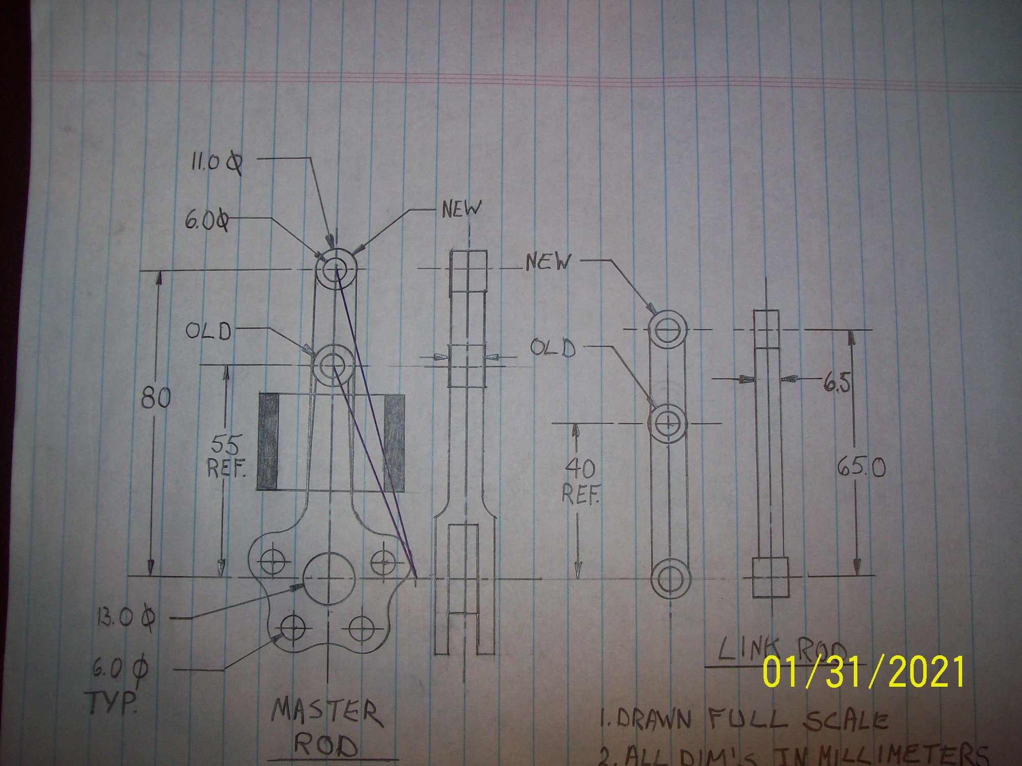
Attached is a drawing of the existing and proposed changes to the Master and Articulated Rods. I bought spare parts from Tower Hobbies, measured and traced the shapes and added pertinent dimensions. You can see the 1" spacer block in cross section shaded) and the interference area between the rod and spacer. I think that this can be resolved by machining a groove on both sides to clear the conrod.
I just purchased an old FA-80 which has the same dimensions as the FA-65 to be used as a guinea pig for experimentation. The first order of business will be to machine the adapter and a simple conrod to test the feasibility based on true, actual parts. If that works, I will machine the master rod from Al. 7075 and go from there.
Is there enough interest in this for me to keep posting?
I have already answered this question but thanks for chiming in.
The airplane does not need more than a 50 cc radial. The scale appearance and sound are important to me hence considering this undertaking. There is NO radial on the market that is around 11" in diameter AND 50 CC displacement. To get the diameter close - I will need to go to a UMS 5-260 CC which weighs 12 Lbs. and could fly a 1/2 scale Sportwing at 1/3 throttle. The $3,100 price tag is another story altogether.
Attached is a drawing of the existing and proposed changes to the Master and Articulated Rods. I bought spare parts from Tower Hobbies, measured and traced the shapes and added pertinent dimensions. You can see the 1" spacer block in cross section shaded) and the interference area between the rod and spacer. I think that this can be resolved by machining a groove on both sides to clear the conrod.
I just purchased an old FA-80 which has the same dimensions as the FA-65 to be used as a guinea pig for experimentation. The first order of business will be to machine the adapter and a simple conrod to test the feasibility based on true, actual parts. If that works, I will machine the master rod from Al. 7075 and go from there.
Is there enough interest in this for me to keep posting?
01-31-2021, 10:30 AM
#3840
My Feedback: (128)
Join Date: Dec 2003
Location: Naperville,
IL
Posts: 395
Likes: 0
Received 0 Likes
on
0 Posts
I for one am very interested!
I used to fly the FA-170and FA-325, but found they needed to rev a bit too high for my taste. The Seidel/UMS radials have a deeper note because they limit them to 5,500 rpm (soft springs?) - they sound especially good with a Keleo exhaust. Unfortunately, there is not much one can do about all those exhaust pulses and these engines sound best near idle, at least to my ear.
I've been reading some back-issues of "Strictly IC", by the model engine makers. Far beyond my Taig mini-lathe and Craftsman drill press, but one can appreciate their skill. It would be nice to be able to modify existing multi-cylinder glow engines to make them more scale in appearance.
01-31-2021, 11:12 AM
#3841
My Feedback: (66)
I totally botched the drawing in my last post. I re-did it based on the FA-65 dimensions and hopefully got it right this time. Notice that the conrod @ 90 degrees crankpin suggests no interference with the 1" spacer.
I have a Craftsman 12" lathe and a Bridgeport milling machine so the real challenge may be the Master Rod.
For a first go I think that it would be a good idea to try the new concept on a FA-65 (or FA-80) and see how it works. If it does, than I will go for the full radial.
As for good "Radial Sound" - watch this video:
I think that running a 22-10 propeller on a gas converted FA-325 will limit it to under 5,000 rpm with great sound in the air.
Josh
02-01-2021, 04:07 AM
#3844
Redball8
I have already answered this question but thanks for chiming in.
The airplane does not need more than a 50 cc radial. The scale appearance and sound are important to me hence considering this undertaking. There is NO radial on the market that is around 11" in diameter AND 50 CC displacement. To get the diameter close - I will need to go to a UMS 5-260 CC which weighs 12 Lbs. and could fly a 1/2 scale Sportwing at 1/3 throttle. The $3,100 price tag is another story altogether.
Attached is a drawing of the existing and proposed changes to the Master and Articulated Rods. I bought spare parts from Tower Hobbies, measured and traced the shapes and added pertinent dimensions. You can see the 1" spacer block in cross section shaded) and the interference area between the rod and spacer. I think that this can be resolved by machining a groove on both sides to clear the conrod.
I just purchased an old FA-80 which has the same dimensions as the FA-65 to be used as a guinea pig for experimentation. The first order of business will be to machine the adapter and a simple conrod to test the feasibility based on true, actual parts. If that works, I will machine the master rod from Al. 7075 and go from there.
Is there enough interest in this for me to keep posting?
02-02-2021, 10:55 AM
#3845
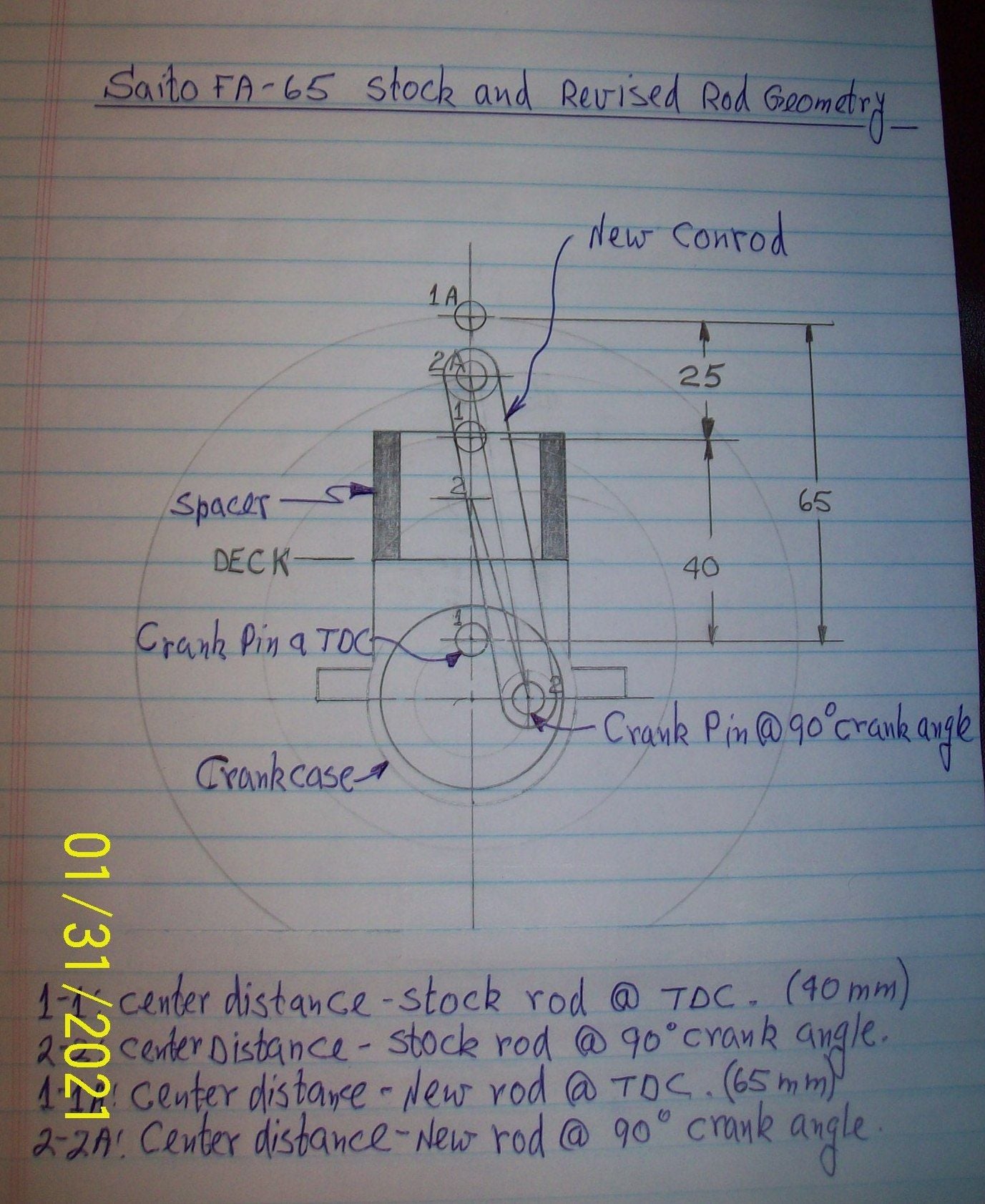
I totally botched the drawing in my last post. I re-did it based on the FA-65 dimensions and hopefully got it right this time. Notice that the conrod @ 90 degrees crankpin suggests no interference with the 1" spacer.
I have a Craftsman 12" lathe and a Bridgeport milling machine so the real challenge may be the Master Rod.
I have a Craftsman 12" lathe and a Bridgeport milling machine so the real challenge may be the Master Rod.
If you have access to/know someone with a small CNC, the master rod should be pretty simple. I had a rod/crank pin interface start galling on an (ab)used Saito FA170-R3, so modeled one up in CAD and machined up a replacement in 6061 on a tiny Sherline mill.
Dissolved off the aluminum debris on the crank pin with muriatic acid and pressfit a bronze bushing into the (ever so slightly oversize) master rod and it�s been fine ever since.
02-05-2021, 06:22 AM
#3847
My Feedback: (66)
Update:
I got a Saito FA-80 to be used as a test bed for the extra tall cylinder. The engine was partially disassembled to check the feasibility of adding a spacer block, longer conrod, new pushrods and tubes, and longer intake tube. It is going to involve quite a bit of effort but certainly doable.
Next step is to buy Aluminum 6061 T6 bar stock for machining the spacer(s) and 7075 T6 stock for machining the link rod(s).
In my continued search for engines with extra long conrods, I found that the OS Inline Four Cylinder IL-300 uses extra long ones for the express purpose of capturing the scale appearance (height) of the DeHavilland Gypsy Cirrus engine. The Center Distance in this rod is 60 mm and it is made of Bronze, so - Buckling is apparently is not an insurmountable problem. The real challenge still will be to keep the mass low enough for balance and vibration sake while maintaining structural integrity. My intended center distance is 65 mm.
I photographed the engine and generated an "Artist Impression" with cylinder #1 raised 25 mm. There is of course some distortion but the visual effect is there.
question: I bought a spare FA-325R5D5 link rod P/N SAI325R511 from Tower Hobbies. To my surprise it came with NO Phosphor Bronze bushings in the pin holes. All the pictures of the original radial show bushed link rods. I have noticed that over the years Saito (based on accumulated experience I assume) have been moving away from bushings. Could this be the case here? Does anybody know for sure?
02-05-2021, 05:25 PM
#3848
Not sure about the 325-R5, but most of Saito�s engines were designed using a high-silicon-bearing aluminum alloy with no bushing for conrods.
This was successful for years on their methanol engines, but has been temperamental on some of their gas engines (including radials), which are basically enlarged versions of the original glow engines with gasoline suitable carburetors. Some users have no problems, suggesting it works most of the time. But failures have been occurring, possibly because gasoline lubrication is much lower (both in % of fuel and overall fuel volume flow) and where the end user may be choosing a cheap off-the-shelf oil to add to their gasoline. I believe some of their revised generation radials now have a bronze bushing in the master conrod for the crank pin, but not the slave rods (which makes sense given their significantly limited rotation).
When I made my FA170-R3 replacement master rod, I choose to fab and press a bronze bushing in, as while I�ve heard of unbushed 6061 rods being used on model engines built for occasional gentle static running, I had no delusions of it lasting very long in actual usage on an airborne model tuned for flight power. I did slightly oversize the body of the rod to make up for the reduction in material where the bushing was.
02-05-2021, 05:56 PM
#3849
My Feedback: (66)
darkith
Thank you very much for your comments. I am leaning toward incorporating bushings, perhaps even press in oiltie bushings and then drilling and reaming to .0002 over the pin diameter.
I am very curious about the equipment and methods you used to fabricate the master rod for your FA-170-R3 radial. Can you please elaborate?
Thanks again
Josh
02-06-2021, 09:44 AM
#3850
I modeled it out in CAD (slightly beefened up as mentioned), then milled out the profile in 6061 on a Sherline CNC mill (very small but reasonably accurate bench top mill). I drilled the holes (crank pin, slave rod, and wrist pin) on the mill, and then reamed with appropriate (metric) reamer.
I didn�t have the right reamer for the crank pin, so I put it in a four jaw chuck on the lathe and carefully bored it out.
I turned a piece of bronze to a tight press fit then drilled and bored the bearing to spec. Pressed it in with temperature differential.
Cross drilled three oil holes into the bushing and one oil hole into each of the wrist/slave pin holes and then tidied up.