


CARF-Models 2013 Series 3.1m Extra 330SC
 08-25-2013, 11:27 AM
#226


The cooling part of the instruction manual addresses the cutouts in the cowl for exit air, the cutouts in the motor dome for air to circulate around the canisters and some additional air exits in the fuselage. The instruction manual has this picture of the air exits in the fuselage. This picture is looking forward at the bottom of the fuselage.

The instructions called for a pair of exits that were 200mm x 50mm. I ended up making mine 9" long by 2" wide. I planned for a 1" wide louver at the front of the exit and a 2" wide baffle extending into the fuselage to grab some air and send it out the bottom.
I covered the bottom of the fuselage with painters tape and marked it out. I put the two exits far enough from the center line so they would not be cutting into the carbon tape on the center seam of the fuselage.

I removed the air exit material and extended the cuts to where the louver and baffle will be hinged.

The instructions called for a pair of exits that were 200mm x 50mm. I ended up making mine 9" long by 2" wide. I planned for a 1" wide louver at the front of the exit and a 2" wide baffle extending into the fuselage to grab some air and send it out the bottom.
I covered the bottom of the fuselage with painters tape and marked it out. I put the two exits far enough from the center line so they would not be cutting into the carbon tape on the center seam of the fuselage.
I removed the air exit material and extended the cuts to where the louver and baffle will be hinged.
 08-25-2013, 11:28 AM
#227
I used a Sharpie to mark the location where the fuselage skin would be "hinged" for the front louver and the rear baffle.

I carefully scored the line with an X-acto knife being careful to only go through the inner layer of the fuselage skin. I ran an aluminum triangle back and forth to remove the majority of the middle layer of the fuselage skin in a double bevel shape.

Check the double bevel a couple times to see if you've removed enough to get the angle you want.

I carefully scored the line with an X-acto knife being careful to only go through the inner layer of the fuselage skin. I ran an aluminum triangle back and forth to remove the majority of the middle layer of the fuselage skin in a double bevel shape.
Check the double bevel a couple times to see if you've removed enough to get the angle you want.
 08-25-2013, 11:31 AM
#230
Score the hinge line for the front louver. This one will be bending out, so the double bevel isn't required. Score the inner and middle skin enough that it bends out comfortably.

The supports are constructed just like they were for the rear baffles, only smaller. This louver is only 1" wide.

The supports are constructed just like they were for the rear baffles, only smaller. This louver is only 1" wide.
08-25-2013, 02:33 PM
#235
I wanted to install the Smart-Fly PowerExpander Competition 12, receiver, and batteries last so they could be mounted where needed to achieve the desired CG. I moved back to the tail to complete those installations.
The first time I put the horizontal stabs on I was amazed at the perfect fit between the fuselage and the stab roots. It was beautiful.

The bolts into the stab tube were drilled perfectly by the factory and positioned the stabs tight against the fuselage.


The first time I put the horizontal stabs on I was amazed at the perfect fit between the fuselage and the stab roots. It was beautiful.
The bolts into the stab tube were drilled perfectly by the factory and positioned the stabs tight against the fuselage.
08-25-2013, 02:34 PM
#236
The opening for the elevator servo extension is placed between the stab tube and the carbon anti-rotation pin.

I marked the fuselage above and below the stabilizer with some painters tape.

I cut the opening with the Dremel router bit and used thick CA to add a wire keep on the inside of the opening to hold the elevator servo extension.

I marked the fuselage above and below the stabilizer with some painters tape.
I cut the opening with the Dremel router bit and used thick CA to add a wire keep on the inside of the opening to hold the elevator servo extension.
08-25-2013, 02:35 PM
#237
I added a wire keep to the elevator servo lead to keep it from rubbing on the plywood rib.

The rudder servos have been installed previously. I added wire keeps to the inside of the fuselage to hold the extensions for the four servos in the tail. I used a piece of Viton tubing where the extensions were routed over the plywood former.

I started with all four extensions being routed down the right side of the fuselage. When I have an option, I'm adding things to the right side of the fuselage to try and balance the extra engine weight on the left side of the airframe. The engine has been offset to the left and it needs to be balanced out to achieve neutral lateral balance.

With that said, I ended up moving two of the extensions back to the left side so that the extensions could be connected to the left side of the PowerExpander.
The rudder servos have been installed previously. I added wire keeps to the inside of the fuselage to hold the extensions for the four servos in the tail. I used a piece of Viton tubing where the extensions were routed over the plywood former.
I started with all four extensions being routed down the right side of the fuselage. When I have an option, I'm adding things to the right side of the fuselage to try and balance the extra engine weight on the left side of the airframe. The engine has been offset to the left and it needs to be balanced out to achieve neutral lateral balance.
With that said, I ended up moving two of the extensions back to the left side so that the extensions could be connected to the left side of the PowerExpander.
08-25-2013, 02:35 PM
#238
The nylon thrust bearings had been previously added to the rudder hinges. I hadn't installed the rudder while I was doing all the other installations. I slid the rudder on the hinges and installed the 4mm carbon tube.

Just like the stabs, I left the carbon tube 1/8" short on both ends.

Just like the stabs, I left the carbon tube 1/8" short on both ends.
08-25-2013, 02:36 PM
#239
I trapped the carbon rod into the rudder with a drop of 15 minute epoxy at each end. If I ever need to remove the rudder it will be very easy to grind out the little drop of epoxy and remove the carbon tube.
I put a piece of painters tape over the hole and cut it out.

I put the drop of epoxy in the hole, remove the painters tape, put a piece of clear tape over the glue, and turn the plane upside down while the epoxy cures.
After the epoxy is cured the clear tape is removed and I use a Sharpie to color the seam on top. It is a beautifully clean installation.

The other end of the tube is done the same way before adding the tailwheel assembly.
I put a piece of painters tape over the hole and cut it out.
I put the drop of epoxy in the hole, remove the painters tape, put a piece of clear tape over the glue, and turn the plane upside down while the epoxy cures.
After the epoxy is cured the clear tape is removed and I use a Sharpie to color the seam on top. It is a beautifully clean installation.
The other end of the tube is done the same way before adding the tailwheel assembly.
08-25-2013, 02:38 PM
#240
I finished up the tail by adding the rudder servo turnbuckles and mounting the tailwheel assembly.
I've never liked the angle of the cables steering the tailwheel on a traditional setup. I realized the rudder linkages were on a 1.25" arm. I decided to use a 1.5" servo arm and use the outer hole to drive the tailwheel steering.
The J&J Tailwheel came with the compression springs. Nice!! I used the wire and crimps from a 3DHobbyShop Slick I put together earlier this
year to make the connections. The wire was the perfect size and their crimps made it easy to do.
It turns out this setup has major power steering. Low rate rudder provides very positive steering on the ground. It's an awesome setup with incredible steering authority. 10 mph crosswinds were no problem.
Last edited by Dean Bird; 08-25-2013 at 02:52 PM.
08-25-2013, 04:36 PM
#241
At this point I only had the PowerExpander, receiver, receiver batteries, and pilot figure to install. I tried the suggestion of balancing at the front of the wing tube without the wing on. I had the stabs on, set the equipment listed above into the plane, and put the hatch on. The pilot figure was set in the bottom of the fuselage where it would be mounted. Using this method the PowerExpander, receiver, and receiver batteries needed to be right behind the pilot figure.
I liked the idea of the batteries being mounted up high in the turtledeck. The winner of the Tucson Shootout mentioned something about the vertical CG. Huh? He told me the reason he didn't run canisters wasn't because of the weight. It was because he wasn't willing to have that much weight that low in the plane. This was the first time I had ever heard the "vertical CG" mentioned. Then I saw an article in M.A.N. about hovering. It also mentioned the vertical CG and that moving the weight as high as possible would make the plane hover better.
As you've seen in these installations, I've concentrated on getting things mounted as high as possible. And when the position is optional it's being mounted to the right to balance the engine that has been offset to the left and achieve a neutral lateral balance without adding any wingtip weight.
As happy as I was to have the batteries up in the turtledeck, they didn't stay there. When I actually checked the real CG after everything was mounted, I had to move the batteries. I really wished I would have put the plane together and asked my wife or son for assistance in checking the CG before I mounted the PowerExpander, receiver, and receiver batteries. It would have saved me a lot of wasted time mounting things in the wrong location.
08-25-2013, 04:37 PM
#242
I mounted the PowerExpander in the fuselage behind the pilot figure. I used the rails that were intended for the rudder servo tray.

The front rail is glued on top of the fuselage stringer. The rear rail is supported by some triangle stock. The PowerExpander is mounted on top of 1/4" plywood standoffs. I mounted it off to the right a little thinking the extensions for all four servos in the tail would be on that side. And I wanted to get more weight on the right side.

The front rail is glued on top of the fuselage stringer. The rear rail is supported by some triangle stock. The PowerExpander is mounted on top of 1/4" plywood standoffs. I mounted it off to the right a little thinking the extensions for all four servos in the tail would be on that side. And I wanted to get more weight on the right side.
08-25-2013, 04:38 PM
#244
I chose to use the Smart-Fly pin/flag switch with the PowerExpander. No switches on the outside of the plane.
A hole is drilled where you want to insert the "pin" into the fuselage.

I made a plate to bolt on the receptacle and added standoffs for the nut that is holding it onto the plate. I inserted the pin through the fuselage side into the receptacle.

Use a little thick CA on the standoffs and tack it to the fuselage side with the pin still inserted into the receptacle.

Remove the pin and add some additional thick CA around the standoffs to make sure it's secure. Don't get any glue near the receptacle.
A hole is drilled where you want to insert the "pin" into the fuselage.
I made a plate to bolt on the receptacle and added standoffs for the nut that is holding it onto the plate. I inserted the pin through the fuselage side into the receptacle.
Use a little thick CA on the standoffs and tack it to the fuselage side with the pin still inserted into the receptacle.
Remove the pin and add some additional thick CA around the standoffs to make sure it's secure. Don't get any glue near the receptacle.
08-25-2013, 04:39 PM
#245
The throttle servo extension had the connector added at the correct length and was plugged into the PowerExpander. The extensions from the servos in the tail had been connected. The aileron servos still needed connected.
I chose to use Multiplex connectors for the aileron servos. The only reason being I was so tired of trying to build connectors that soldering actually sounded easier.")
I added the connector to the ends of the aileron servo extensions and secured them to the wing root with two wire keeps.

I put the wing on and marked the top of the wing on the fuselage side.

I added indicators for where the ends of the hole in the fuselage side should be for the aileron extensions to come through.

I chose to use Multiplex connectors for the aileron servos. The only reason being I was so tired of trying to build connectors that soldering actually sounded easier.
I added the connector to the ends of the aileron servo extensions and secured them to the wing root with two wire keeps.
I put the wing on and marked the top of the wing on the fuselage side.
I added indicators for where the ends of the hole in the fuselage side should be for the aileron extensions to come through.
08-25-2013, 04:40 PM
#246
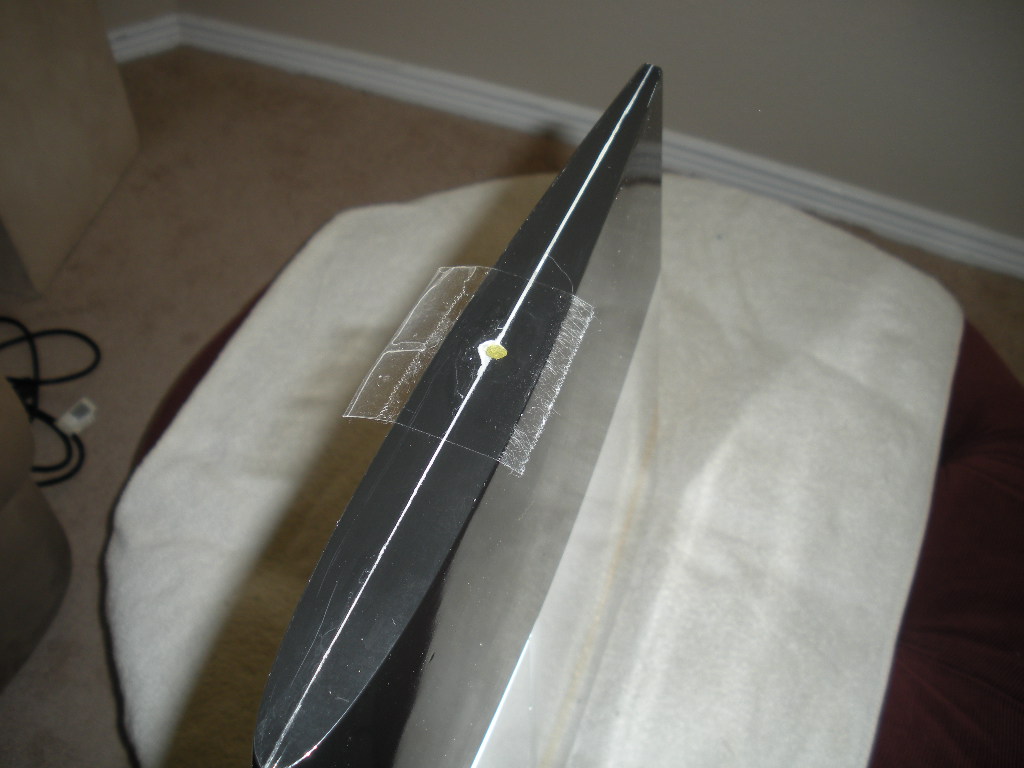
I measured how far the extensions were below the wing skin. I added another piece of tape, marked that location, and use the Dremel router bit to open the hole.

The aileron extension was made long enough to leave about 4" inside the fuselage. This is a picture of the left side.

The is a picture of the right side after the wire keeps were added to the inside.
The wing is mounted, the extensions are secured in the wire keeps, then I have the other side of the Mutliplex connector attached with Velcro to the fuselage side where I put the circle.

If I could find those brackets that hold a Multiplex connector, I'd like to mount the connector into the fuselage side at the wing root. I've seen pictures where the connection is made on the outside of the fuselage before the wing is slid all the way on.
The aileron extension was made long enough to leave about 4" inside the fuselage. This is a picture of the left side.
The is a picture of the right side after the wire keeps were added to the inside.
The wing is mounted, the extensions are secured in the wire keeps, then I have the other side of the Mutliplex connector attached with Velcro to the fuselage side where I put the circle.
If I could find those brackets that hold a Multiplex connector, I'd like to mount the connector into the fuselage side at the wing root. I've seen pictures where the connection is made on the outside of the fuselage before the wing is slid all the way on.
 08-31-2013, 03:52 PM
#249
The pilot figure is installed next. I chose to build a small 1/8" lite-ply platform under each shoulder of the pilot figure.

The lite-ply platform was glued on top of two rails of the 1/8" x 1/2" bass and some balsa triangle stock.

The bass and the lite-ply were shaped to conform to the fuselage side right underneath the hatch rail.

The lite-ply platform was glued on top of two rails of the 1/8" x 1/2" bass and some balsa triangle stock.
The bass and the lite-ply were shaped to conform to the fuselage side right underneath the hatch rail.
08-31-2013, 03:54 PM
#250
The platforms for the pilot figure weighed .4 ounces each.

I glued the platforms in with a little 15 minute epoxy after preparing the fuselage side.

The rails were longer than the lite-ply to provide some additional gluing area with the fuselage side. The bass rails were glued right in front of the plywood at the hatch tabs.

The platform is trapped between the bass rails/triangle stock on the bottom and the hatch opening stringer on the top. The platform is VERY secure.
I glued the platforms in with a little 15 minute epoxy after preparing the fuselage side.
The rails were longer than the lite-ply to provide some additional gluing area with the fuselage side. The bass rails were glued right in front of the plywood at the hatch tabs.
The platform is trapped between the bass rails/triangle stock on the bottom and the hatch opening stringer on the top. The platform is VERY secure.