


Balsa USA Stingray 120
 04-12-2014 | 06:22 PM
#51

Thread Starter

My Feedback: (7)
Joined: Mar 2010
Posts: 120
Likes: 0
Received 0 Likes
on
0 Posts
From: Fayetteville, AR
I got it straight from Sig. It's a Four Star 120 landing gear.
The manual calls for sheeting over the top of the fuse behind the firewall. This area is normally for the fuel tank but will be the battery tray if I go electric. I'm making a hatch for it. Either way, glo or e-power, it will be handy to have access.
I just need to whittle it down and sand it into shape.
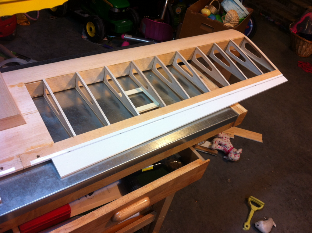
I need to add a couple more formers/supports.

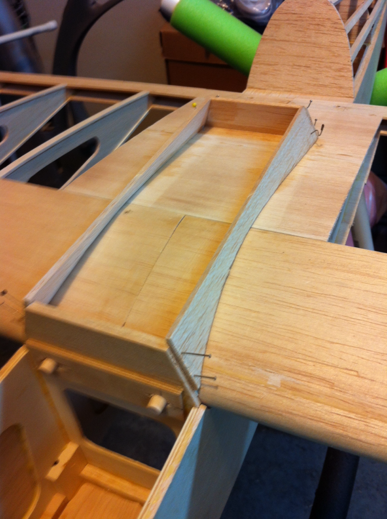
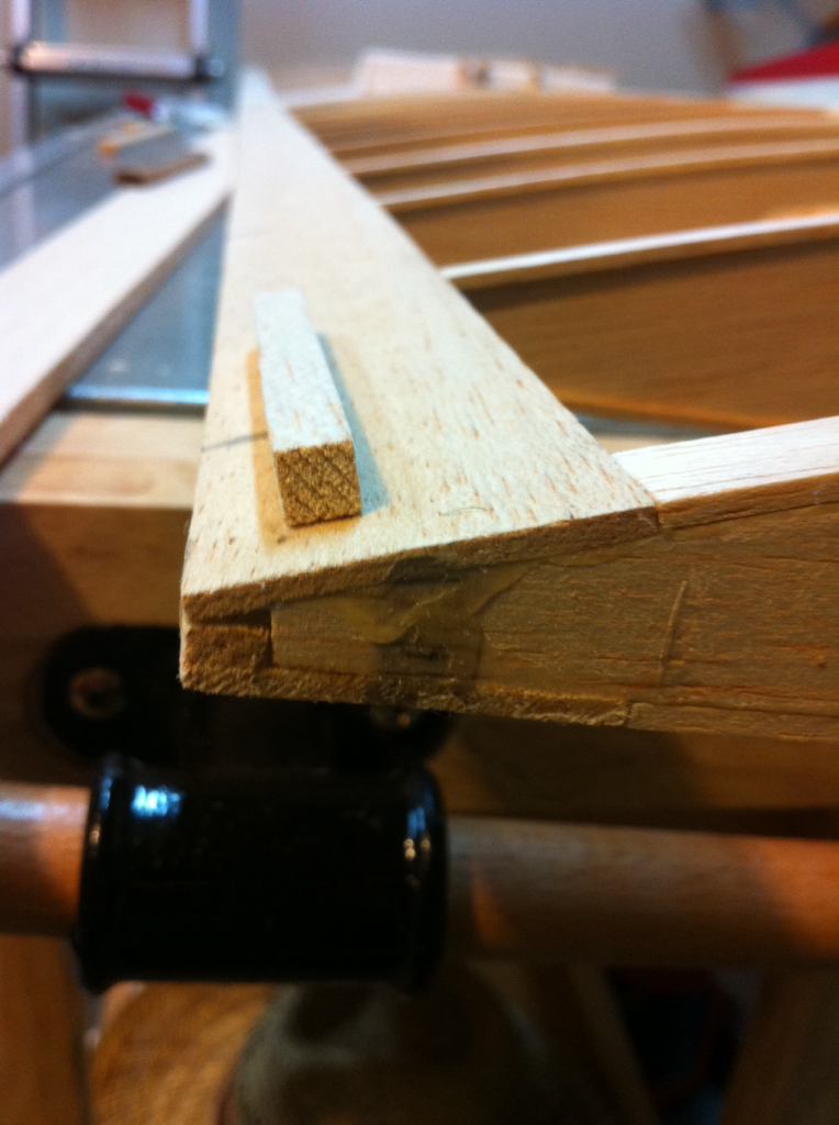
This part is permanently attached to the top center of the wing. It'll form the cockpit and stop where the instrument panel would be.
The manual calls for sheeting over the top of the fuse behind the firewall. This area is normally for the fuel tank but will be the battery tray if I go electric. I'm making a hatch for it. Either way, glo or e-power, it will be handy to have access.
I just need to whittle it down and sand it into shape.
I need to add a couple more formers/supports.
This part is permanently attached to the top center of the wing. It'll form the cockpit and stop where the instrument panel would be.
 04-27-2014 | 01:16 PM
#54
Thread Starter
My Feedback: (7)
Joined: Mar 2010
Posts: 120
Likes: 0
Received 0 Likes
on
0 Posts
From: Fayetteville, AR
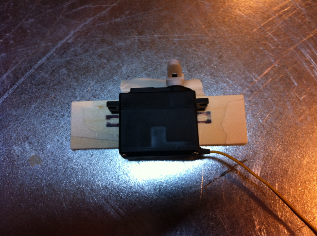
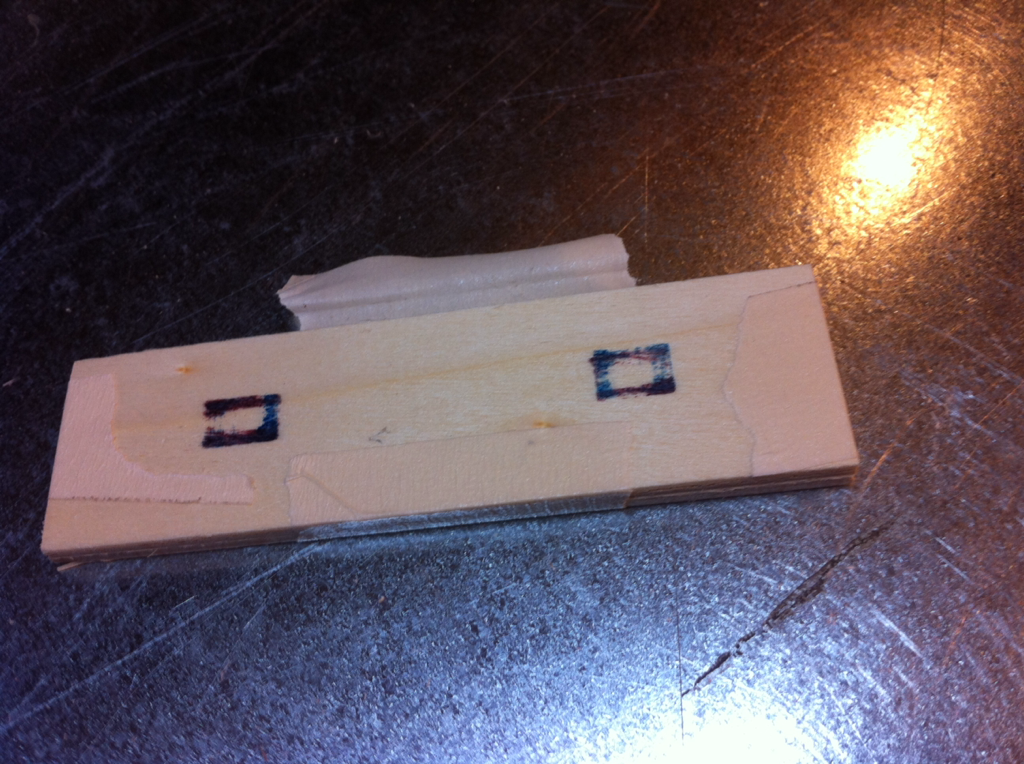
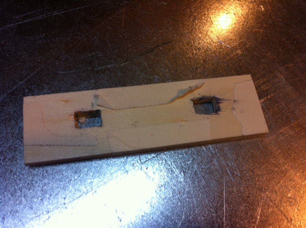
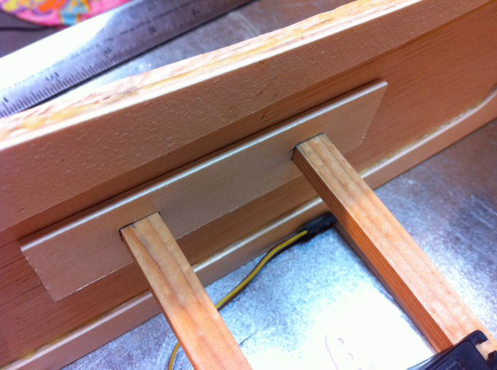
Time to make servo hatches. The plans call for mounting the servos in b/wn a couple ribs on hardwood rails and the push rod exits through a slot in the covering material. No call for an access panel. It would seem the servo is to be covered over completely.
I'm going to go the servo hatch access door route.
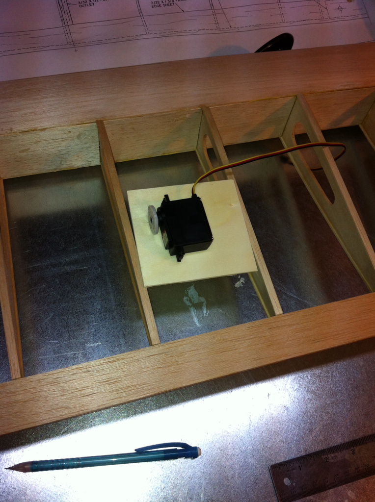
I used 3/32" light ply so it would match the cap strips. I used the same light ply b/wn the ribs to form a frame for the door to sit on.
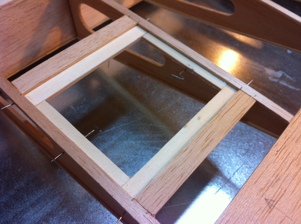
I used some balsa strips on the ends so the covering material would have something to grab on to.
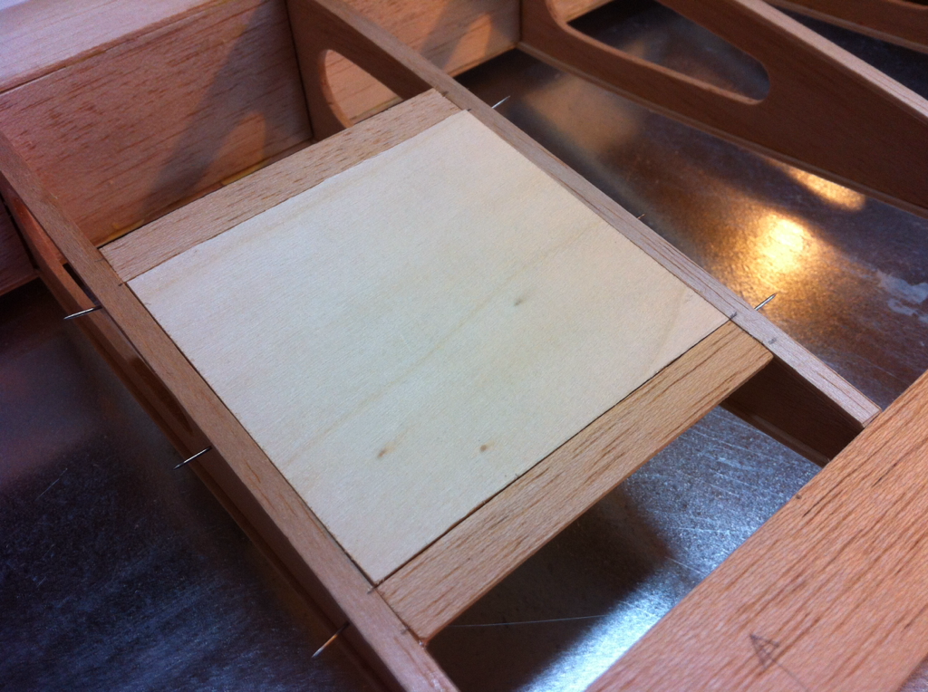
I put some triangle stock on the underside for a little added support.
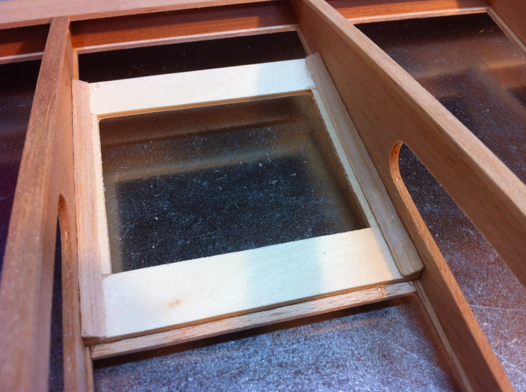
I used thick CA for all the bonding for this.
I'm going to go the servo hatch access door route.
I used 3/32" light ply so it would match the cap strips. I used the same light ply b/wn the ribs to form a frame for the door to sit on.
I used some balsa strips on the ends so the covering material would have something to grab on to.
I put some triangle stock on the underside for a little added support.
I used thick CA for all the bonding for this.
05-03-2014 | 06:59 PM
#56
Thread Starter
My Feedback: (7)
Joined: Mar 2010
Posts: 120
Likes: 0
Received 0 Likes
on
0 Posts
From: Fayetteville, AR
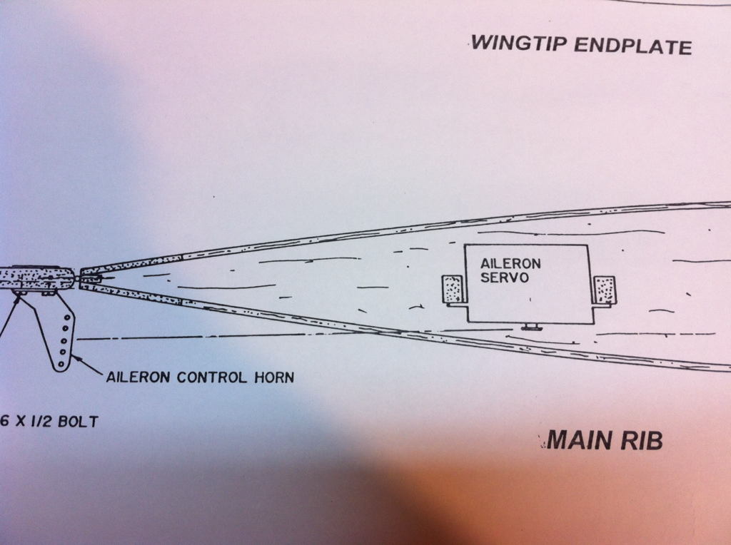
So now the problem is that there's hardly any material to attach aileron hinges to.

This is the 3/16" point hinge...too big it seems.

I'm not sure the size but the small point hinge will have to do.

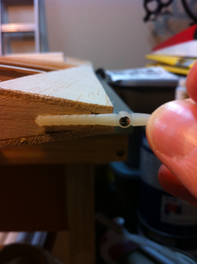
I'm adding some trimmed down 1/4 x 1/2" balsa to the inside of the trailing edge. There's just not enough there for any hinge to grab onto.

Here it is installed with thick CA.


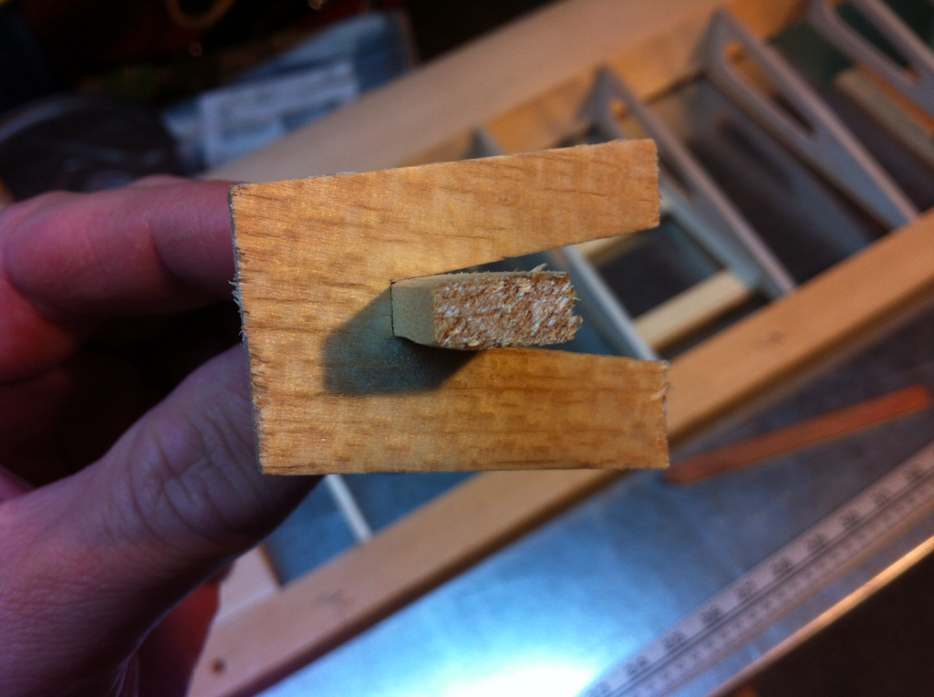
This is the 3/16" point hinge...too big it seems.
I'm not sure the size but the small point hinge will have to do.
I'm adding some trimmed down 1/4 x 1/2" balsa to the inside of the trailing edge. There's just not enough there for any hinge to grab onto.
Here it is installed with thick CA.
Last edited by bicyclemonkey; 05-03-2014 at 07:02 PM.
05-03-2014 | 08:26 PM
#57
Thread Starter
My Feedback: (7)
Joined: Mar 2010
Posts: 120
Likes: 0
Received 0 Likes
on
0 Posts
From: Fayetteville, AR
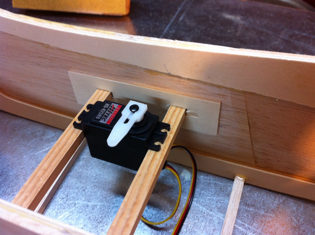
Preparing to mount the servos in the fuselage. The manual gave no mention of ways to mound the servos in the fuse, it just showed the recommended location of the servos. Here's what I did.
I cut a couple pieces of 3/32" ply from Hobby Lobby and used the hardwood servo rails that were supplied with the kit and stamped the location with an ink pad.
Drilled and filed the holes for the mounting rails.
Now it's time to glue to the inside of the fuse. I've been using a bottle of thick CA that I'm trying to use up before it goes dry.
05-04-2014 | 09:20 AM
#58
Hey Bicyclemonkey,
Was wondering which servo you show mounted? Throttle?? Love those adjustable arms, and have used them a lot - but mostly on 40 sz planes .
Do wish someone would make a good stiff metal one with mabey the bottom part being adaptable to fit many different splines.
TH has their TL150's on sale which is what I was thinking of using. Plan on running many different engines and suspect some will put plenty of stress on control surfaces.
T-man49 in Al
Spitfire 19, P38 16
Saito 723, BUSA 37
Sig 24, Glow 33
05-10-2014 | 06:43 AM
#59
Thread Starter
My Feedback: (7)
Joined: Mar 2010
Posts: 120
Likes: 0
Received 0 Likes
on
0 Posts
From: Fayetteville, AR
I got the holes drilled in the side of the fuse for the pushrod housings.
They will be sanded flush with the fuse so all you'll see is the 4-40 rod.
Here's a close up.
I used a 3/16" brass tube that I sharpened on the end since it cuts cleaner holes than a drill bit.
 05-18-2014 | 08:13 AM
#62
Thread Starter
My Feedback: (7)
Joined: Mar 2010
Posts: 120
Likes: 0
Received 0 Likes
on
0 Posts
From: Fayetteville, AR
Thanks, and that's what my wife drives, S40 T5. I bought it new in 2006. It's the longest we've ever kept a car lol.
Getting very close to covering this baby!
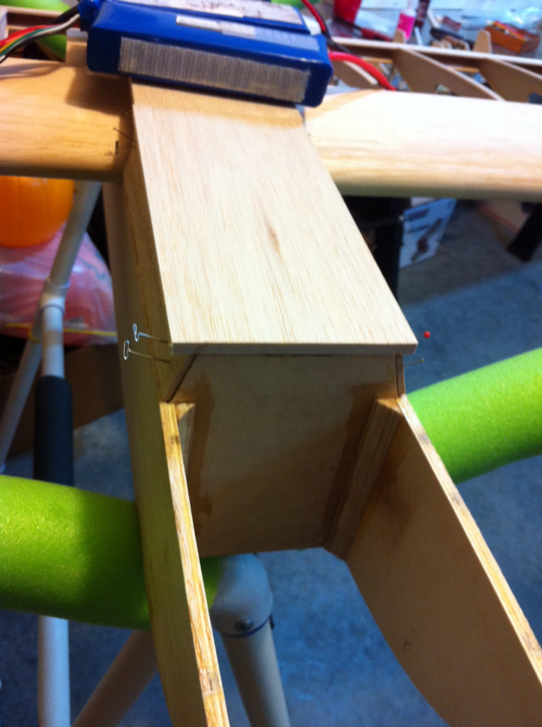
Got the blocks to support the battery tray I had to make glued in place.
Battery (or fuel tank) tray from the bottom.
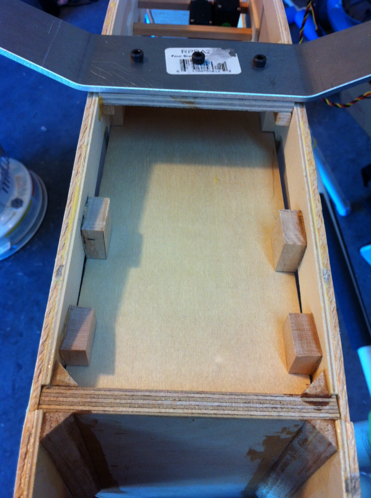
From the top.

Getting very close to covering this baby!
Got the blocks to support the battery tray I had to make glued in place.
Battery (or fuel tank) tray from the bottom.
From the top.


 06-29-2014 | 12:50 PM
#69
Thread Starter
My Feedback: (7)
Joined: Mar 2010
Posts: 120
Likes: 0
Received 0 Likes
on
0 Posts
From: Fayetteville, AR
The aileron hinge holes are drilled. Now It's time to start the covering. Unfortunately I don't have enough of any base color to complete so I ordered a boatload of covering film from both HobbyKing and HobbyPartz. Seriously, I probably won't ever run out lol.

06-29-2014 | 02:38 PM
#70
Thread Starter
My Feedback: (7)
Joined: Mar 2010
Posts: 120
Likes: 0
Received 0 Likes
on
0 Posts
From: Fayetteville, AR
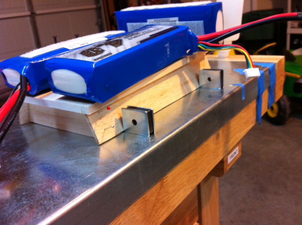
I'm going to get the motor mounted before I glue the tail on. This way I can stand the fuse up on the end to line up the motor.
There was no thrust angle built into the firewall on this kit and the instructions make no mention of any thrust angles. I may mount the motor just slightly to the left so if I need to add some right thrust, the motor won't look crooked.


I just noticed that on my kit build Four Star 120, the engine is square on the end of the fuse and it flies perfect.
https://www.youtube.com/watch?v=dlX9DUxUJyY
There was no thrust angle built into the firewall on this kit and the instructions make no mention of any thrust angles. I may mount the motor just slightly to the left so if I need to add some right thrust, the motor won't look crooked.
I just noticed that on my kit build Four Star 120, the engine is square on the end of the fuse and it flies perfect.
https://www.youtube.com/watch?v=dlX9DUxUJyY


 07-06-2014 | 07:46 PM
#72
Thread Starter
My Feedback: (7)
Joined: Mar 2010
Posts: 120
Likes: 0
Received 0 Likes
on
0 Posts
From: Fayetteville, AR
Actually, I was able to add another small spacer and the screw was long enough, there'll be enough prop clearance cause there'll be a spinner back plate behind the prop.


 08-21-2014 | 08:13 AM
#74
Thread Starter
My Feedback: (7)
Joined: Mar 2010
Posts: 120
Likes: 0
Received 0 Likes
on
0 Posts
From: Fayetteville, AR
Covering has begun!
Right aileron done.

I attached a strip of covering on the trailing edge so I could go ahead and glue the hinges on.
Here's the point hinge glued into the aileron.
All glued in with Titebond II
Right aileron done.
I attached a strip of covering on the trailing edge so I could go ahead and glue the hinges on.
Here's the point hinge glued into the aileron.
All glued in with Titebond II

