


Aristo-Craft D17s Staggerwing
 07-23-2016 | 07:14 PM
#1

Thread Starter

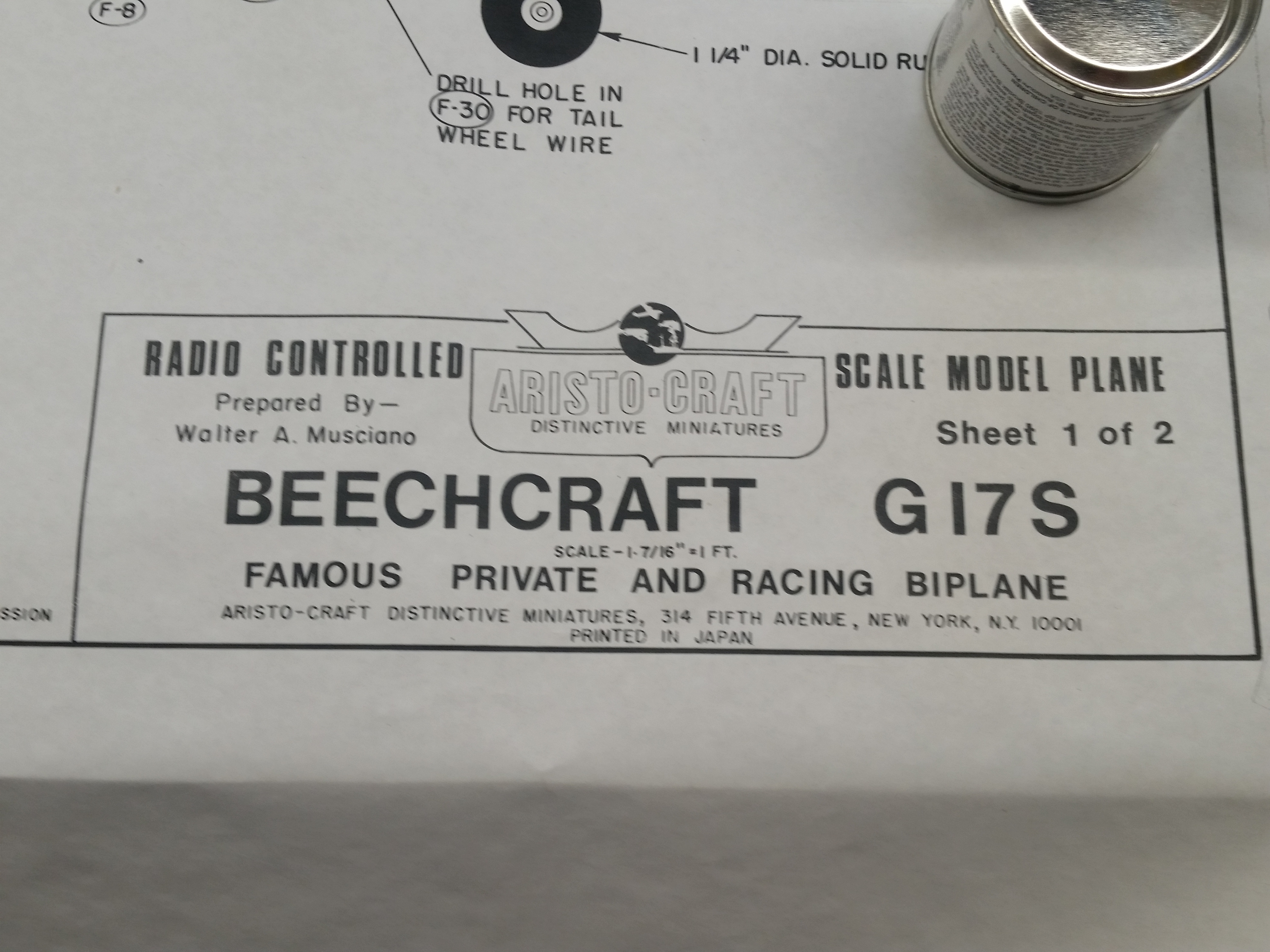
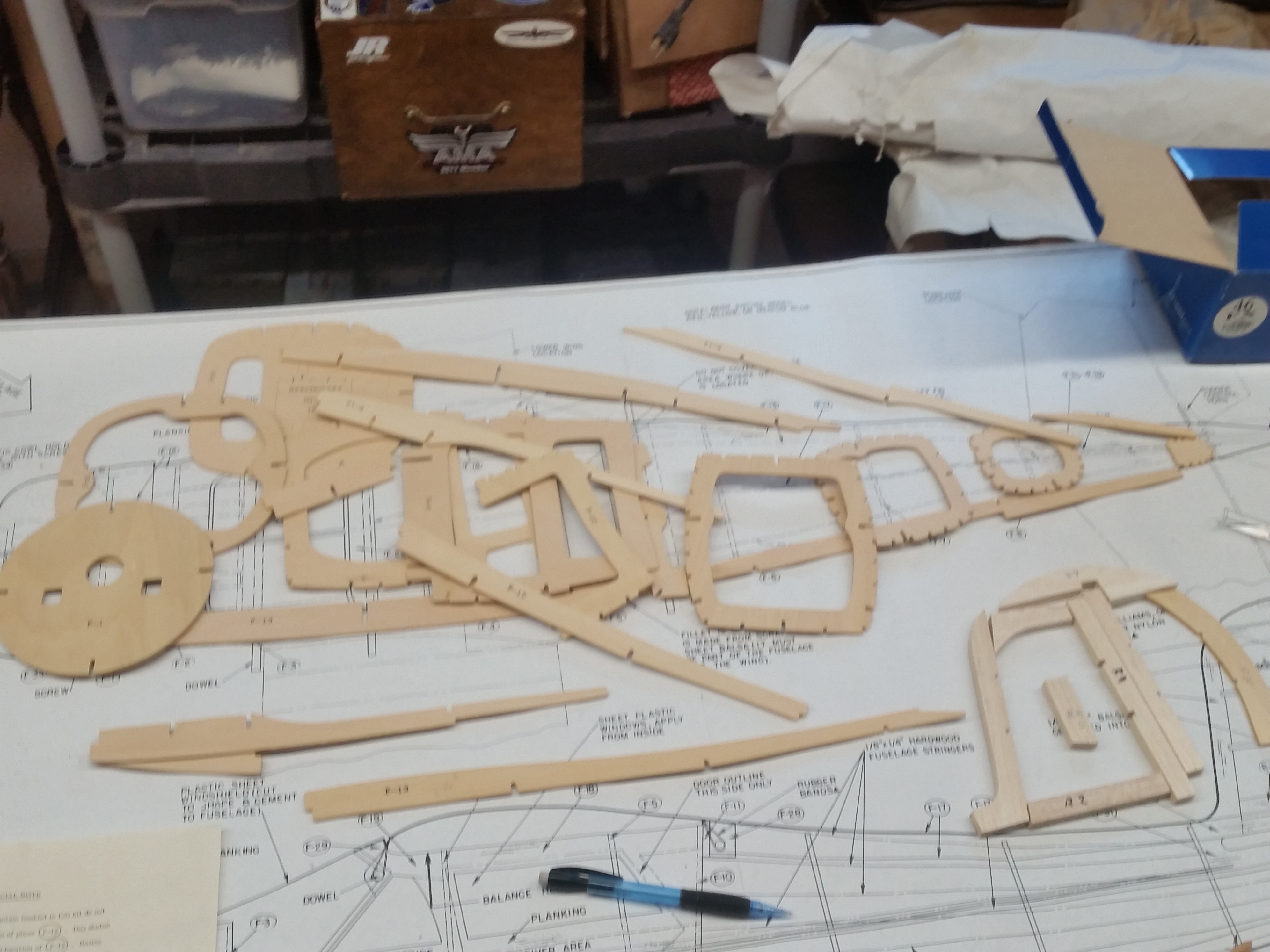
I haven't quite finished up with the BUSA Force One but a new work bench calls for a new build. I picked up an Aristocraft Staggerwing Kit from Eddie at Lazerworks a while back and have wanted to build it but building a house and moving have gotten in the way of hobby activities for the last year or so. This kit dates back to the mid seventies with a copyright date of 1976 on the plans. The plans are credited as prepared by Walt Musciano. Much like the Royal Kits of the same era this kit seems to have actually been made in Japan. As I understand it Aristo-Craft was the house brand for Polk Hobbies. The "Giant Scale" kit spans 45 inches and calls for a .19 to .45 engine. The kit seems to be of high quality with lots of spruce stick wood. About the only place you see the balsa is in the ribs, sheeting and the tail surfaces. The formers and some sheet pieces are made from 3 ply plywood. It isn't as light as plywood. One interesting bit is the trailing edge of the rudder. While the rest of the fin and rudder is made from balsa the trailing edge is die cut from the much heavier plywood! Since this is just about the worst place for a heavy piece of wood I will probably make a new part from lighter material. 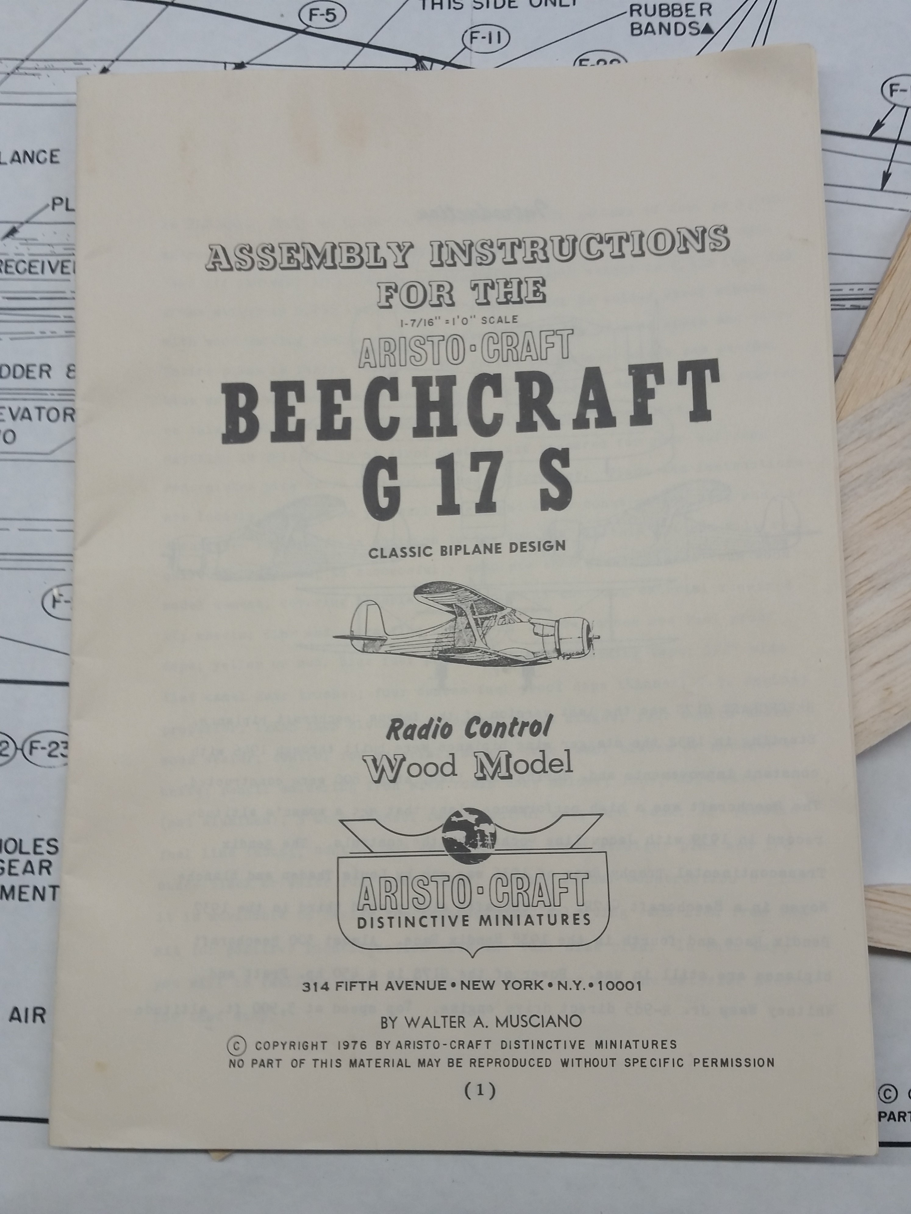
 07-23-2016 | 07:36 PM
#2
Thread Starter
I've started construction of the stagger wing. Building on the 2x6 stands is an idea I borrowed from the large scale guys. They aren't particularly precise but the directions seem to assume that you are building this thing in mid air. There are two notched side formers that the bulkheads key into such that once you begin the fuselage it doesn't lay flat on the plans. The cleanliness of the die cutting on this kit is excellent. The plywood parts come out of the sheets cleanly and easily.The accuracy of the cuts is pretty good but it necessary to square up some of the slots to get a correct fit for the parts. Not a big deal if you notice it ahead of time and clean the slots up with an x-acto knife. One thing that could catch an inexperienced builder out is that some of the parts are mislabeled. Two of the formers in the cockpit area F4 and F5 are labeled in reverse. This prevents being able to assemble things until I figured out what was wrong. There were several other parts that were stamped with the wrong part number. I will be deviating from the plans in some regards. The plans show a three channel plane with lots of dihedral and no ailerons. I will flatten out the wings and add ailerons to the upper wing. This plane is standoff scale at best and without a major redesign of the lower wing and fuselage I don't see much way of doing retracts. Although it is a Staggerwing it doesn't really have the tadpole shape in the fuselage that housed the retracts. This design was intended to use rubber bands to attach the wings and I am going to update to bolt on wings.

 07-25-2016 | 07:56 PM
#4
Thread Starter
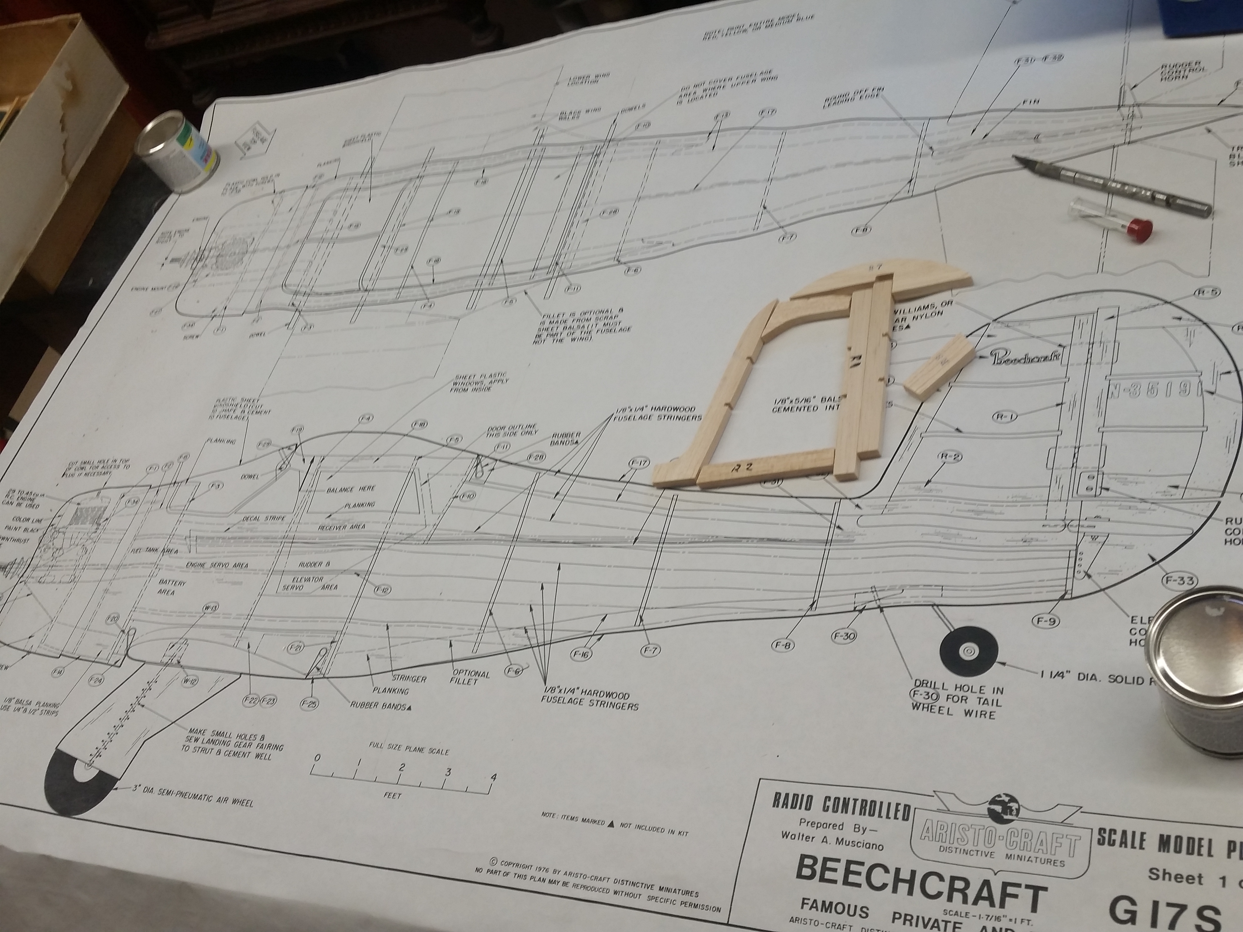
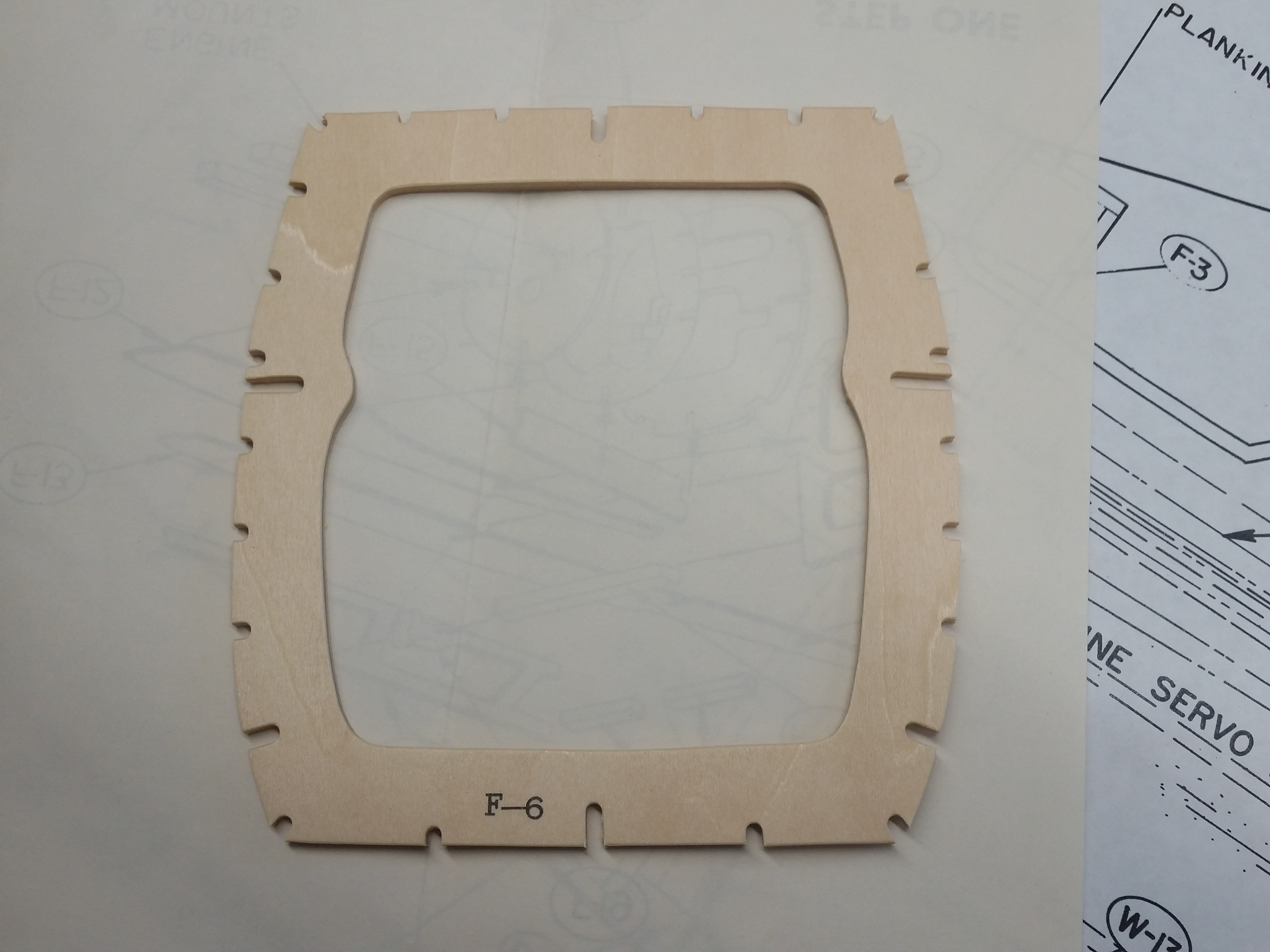
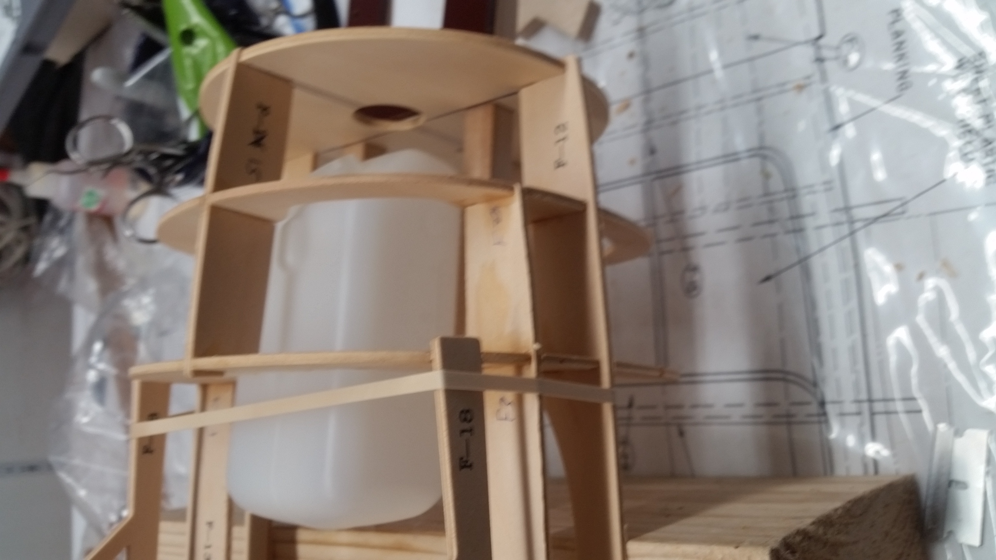
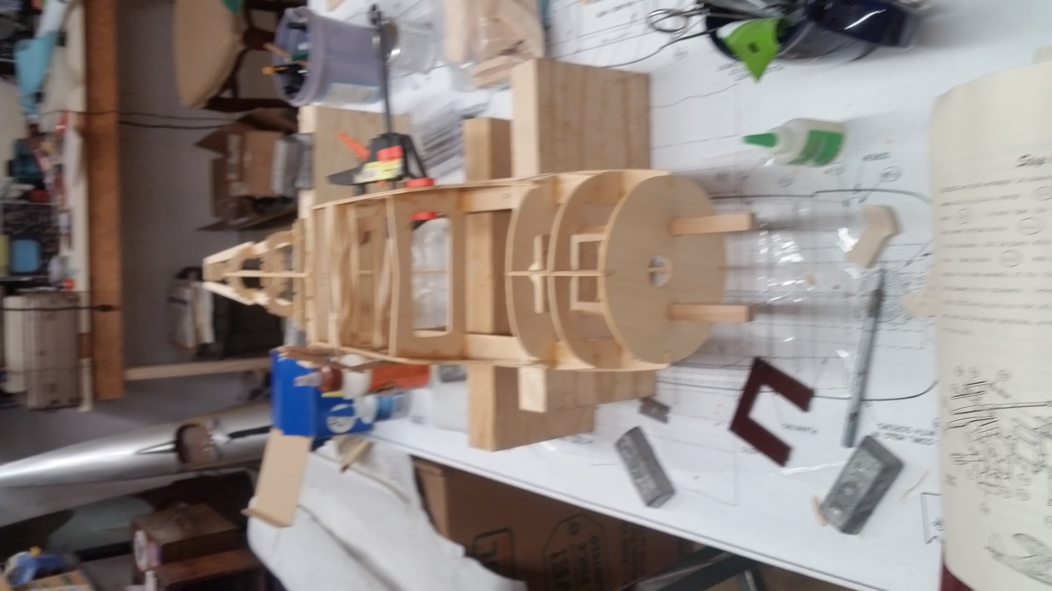
Well the building of the fuselage is fumbling along. This wouldn't have been a good kit for an inexperienced modeler. Someone who cut their teeth on Comet and Cleveland kits might not have had too much trouble. The design, although dated, is good, and as I mentioned the die cuts are neat and clean. They just aren't very accurate. The notches in the formers vary randomly in depth and if not adjusted would twist the stringers. If this kit gets laser cut at some point in the future it would be an easy improvement to ensure the accuracy of the cuts. Another change I am making is changing at least some of the stringers to balsa wood. The kit supplies "hardwood" strip for the stingers. I suspect that it is spruce and while strong the material is overly stiff and adds weight behind the CG. The kit uses beam mounts for the engine. I am going to use these rather than reinforcing the firewall for the black plastic mounts. The beams and the included phenolic plate provide the down and right thrust that the plans call for. The instructions indicate that the fuel tank is to be installed early in the build. I am using the back half of the engine mounts as a platform for the tank and modifying F3 to give me enough room to slide in a modern tank. It looks like there will be plenty of room for standard servos. I wish I knew what the prototype weighed. I think with modern equipment and judicious replacement of wood I can bring it in lighter. I am going to have to replace F9. In addition to being made from heavy ply the notches don't line up. I have carped a lot about this kit but I am actually enjoying the build and am looking forward to having a conveniently sized Staggerwing to take to the field.
07-29-2016 | 08:59 PM
#5
Thread Starter
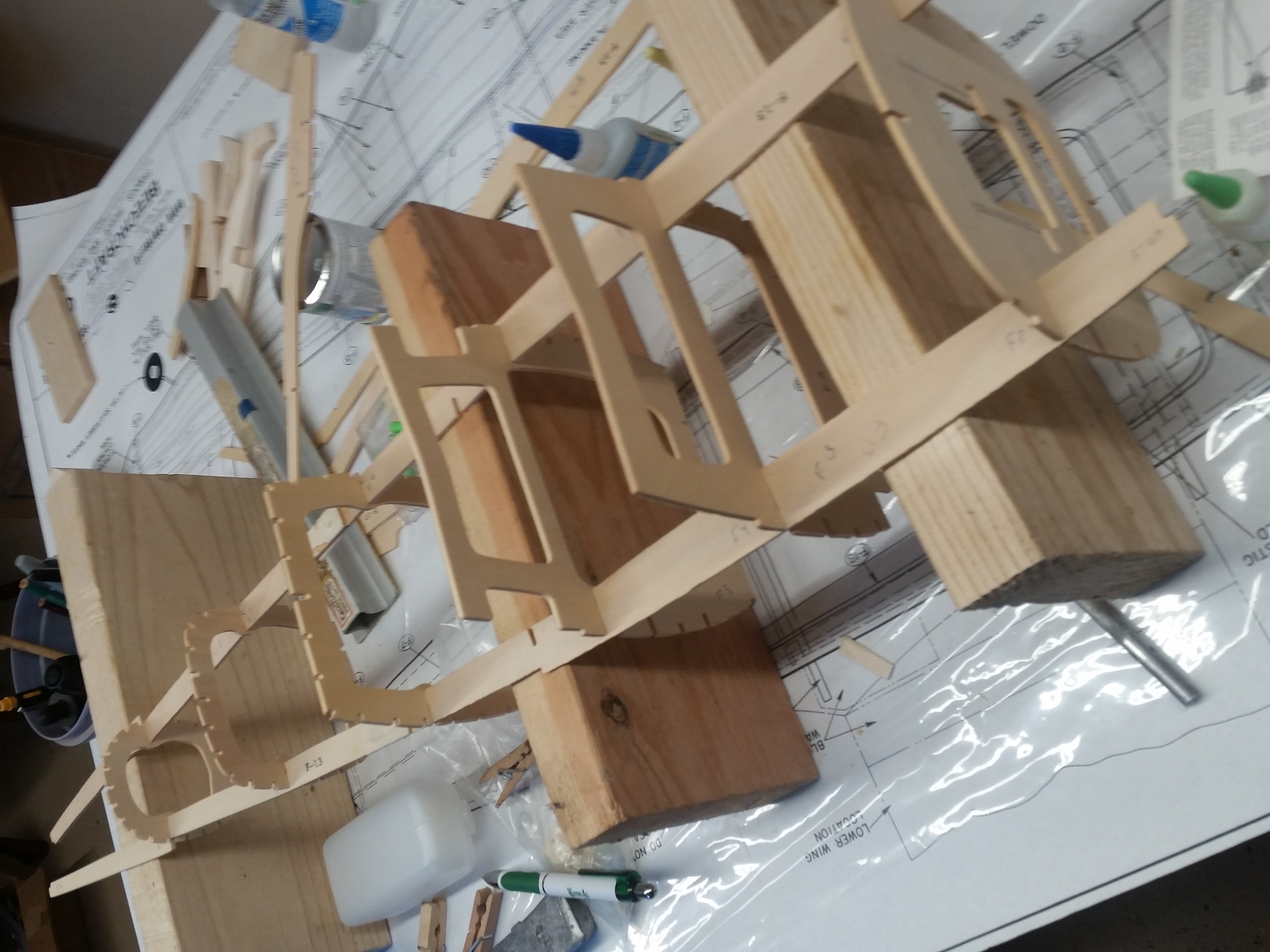
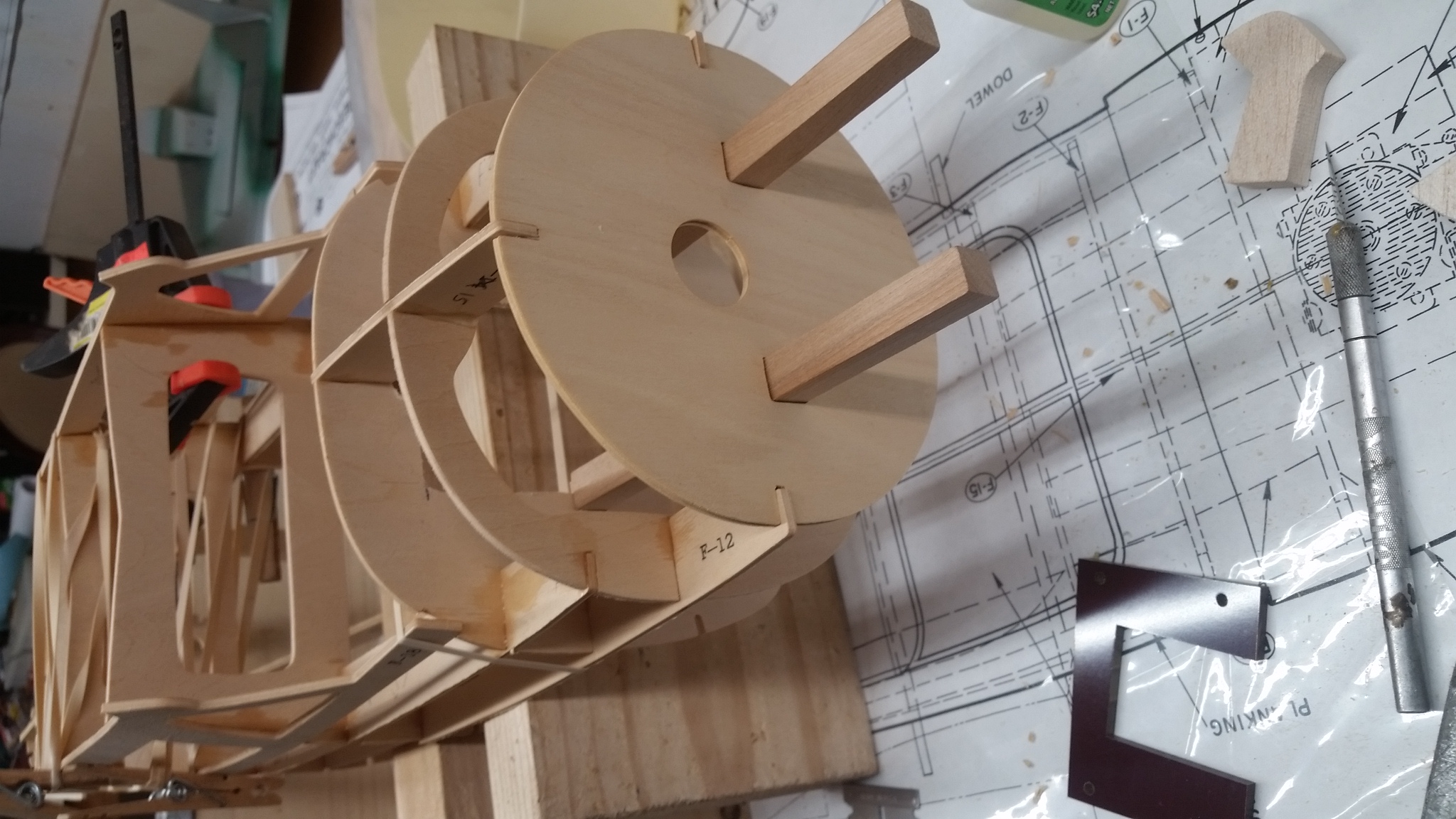
Today pretty much wrapped up the stringers. Since there isn't much of an underlying structure they are technically longerons and are structural. If the formers had been split vertically and the first half of the fuselage assembled flat on the board it would be a lot like a Guillow's rubber model. According to the manual the material for the stringers is 1/8 by 1/4 inch "Japanese Cyprus". It's pretty wood, strong and very stiff. It's also relatively heavy and doesn't particularly like to take a compound curve. I ended up replacing about 16 of the stringers with hard balsa which was much easier to work with and lighter to boot. Where the stringers had a milder curve I kept the cyprus with a mind to using it to link one end of the model with the other. The aftmost former F-9 presented a challenge. I tried making a new one out of 1/8 inch balsa but it has so many notches that it ended up being pretty fragile. I guess I could have cut a new, more accurate F-9 out of aircraft ply but I went with trimming and adjusting the notches on the original part. There are two die cut pieces (F-12) that run down each side of the model locating all of the formers. The ends of these pieces locate the F-9. I cut all of the stingers that attached to F-9 a little long to help with locating the former. The F-12 side pieces have contributed the most with the difficulties due to the notches for the formers being inaccurately cut. Additionally the last four inches of one of the F-12's had a bit of a curve. I addressed this by turning the fuselage upside down so that the parts of the F-12's, which will eventually support the stabilizer saddle, could sit flat on a 2 by 6. With them jigged in place I could glue the F-9 former to the F-12 side pieces and then working side by side the stingers were glued into their notches. The first notch glued was the keel and then working with matching sides I pinched the stringers together and glued them to F9. I also added a piece of 1/8 x 1/4 balsa acrosst he face of F-9 to provide a little extra gluing area. Once the glue set up I was able to trim the ends of the stringers. At this point the fuselage is really taking on a recognizable shape.
07-29-2016 | 09:18 PM
#6
Thread Starter
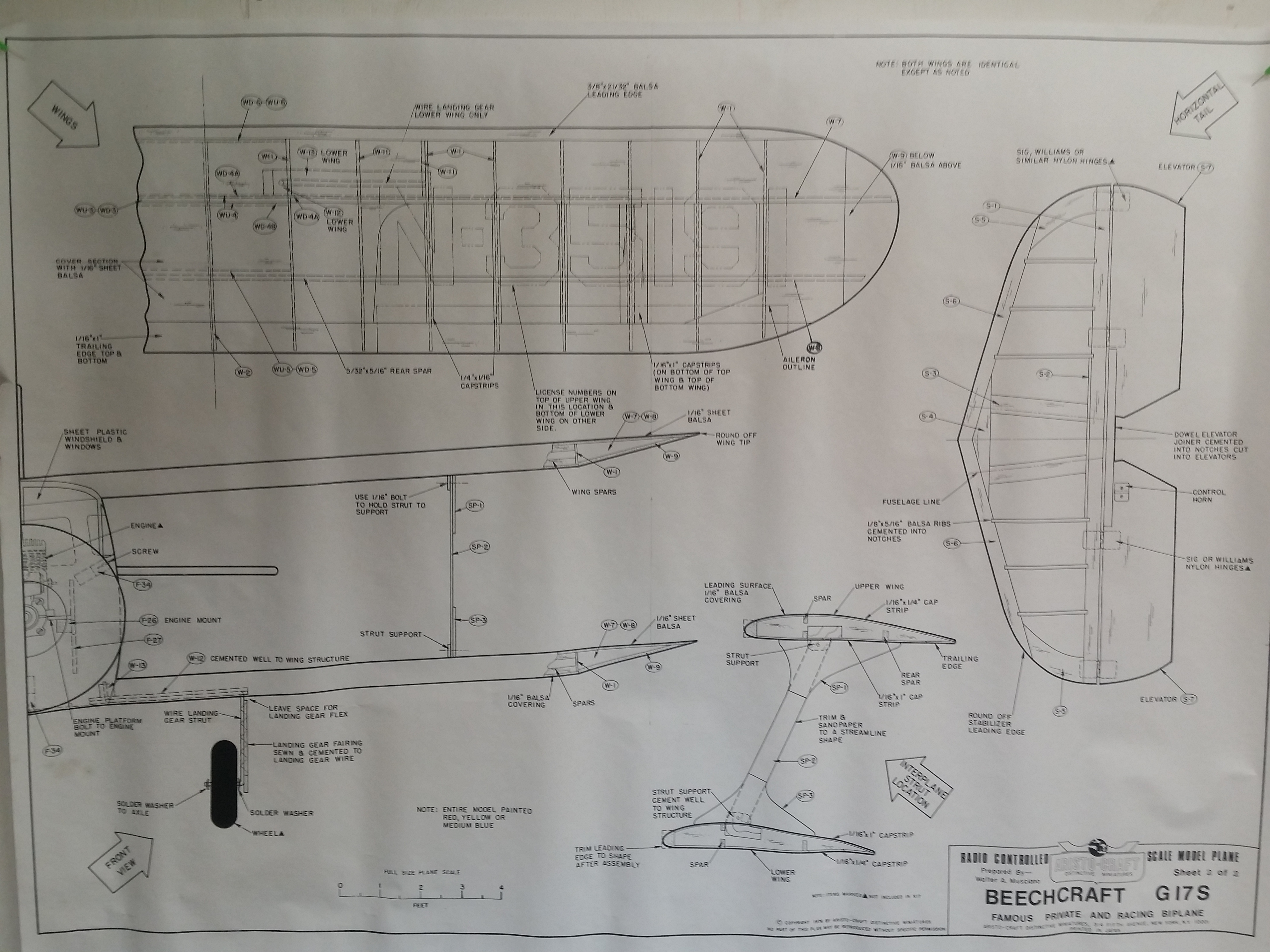
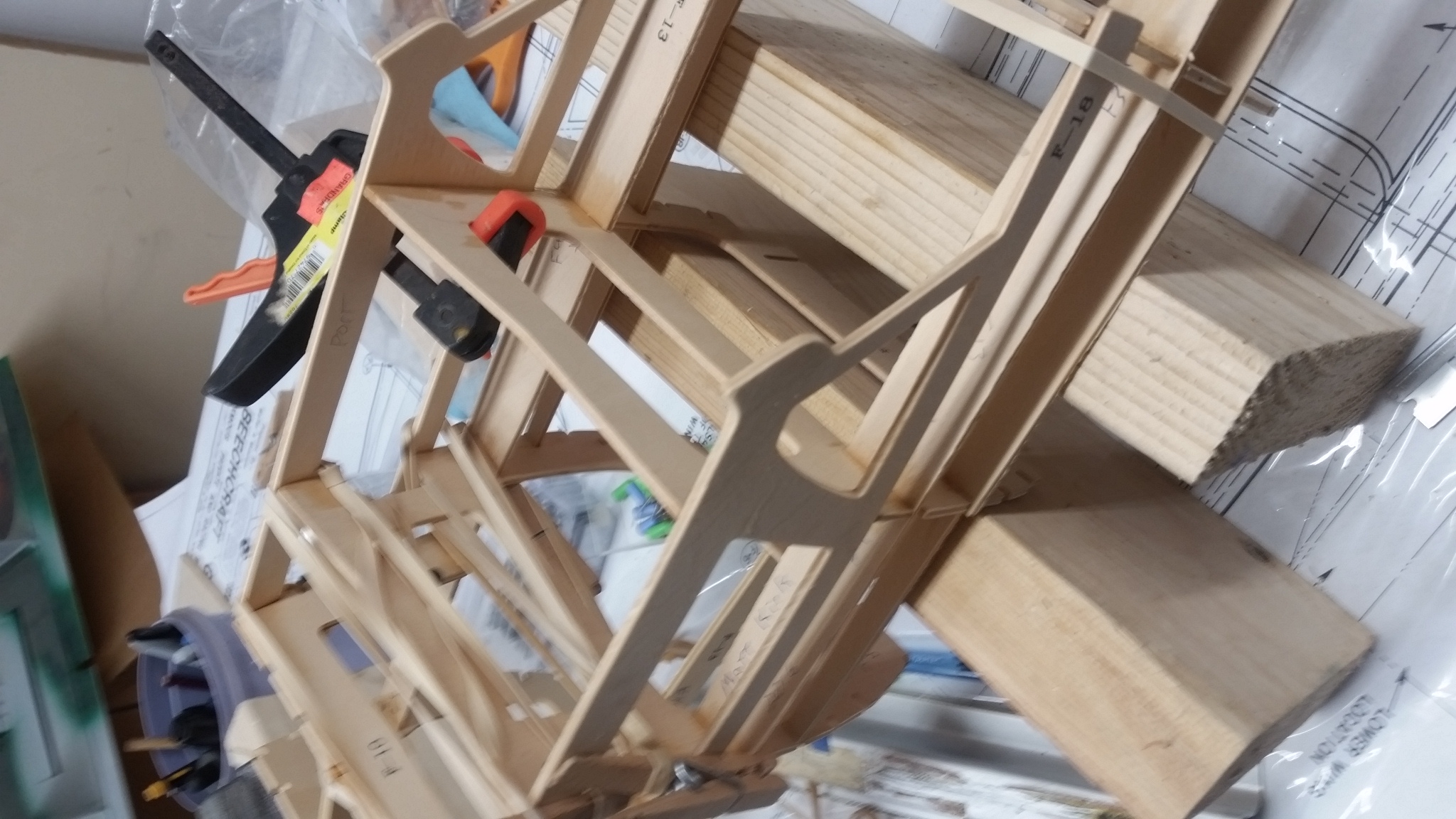
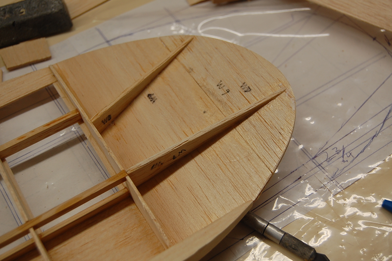
A couple of shots of the lower wing saddle. The instructions amount to make a box, glue it in, sand to match the fuselage contours. So far I haven't found any mention of wing alignment or incidence. The marks on the saddle parts are to help me keep them square. At this point I am going to deviate from the manual and build the wings and tail. This way I can align the supporting structure for the wing and tail before I lock them down and sheet the front half of the fuselage. The alignment of the top wing is set by the top of the fuselage. Once that is true I can use the upper wing to match the incidence of the lower wing and make sure that the horizontal stabilizer is truly horizontal. The plans show a rudder-elevator-throttle model with no ailerons and about two inches of dihedral under each wing tip. A scale upper wing would be built flat with no dihedral. Since my model will have ailerons I am going to have a flat upper wing and reduce the lower wing dihedral to about to about 1/2 inch at the wing tips. I will also modify the center sections for bolt on wings.
08-02-2016 | 07:51 PM
#7
Thread Starter
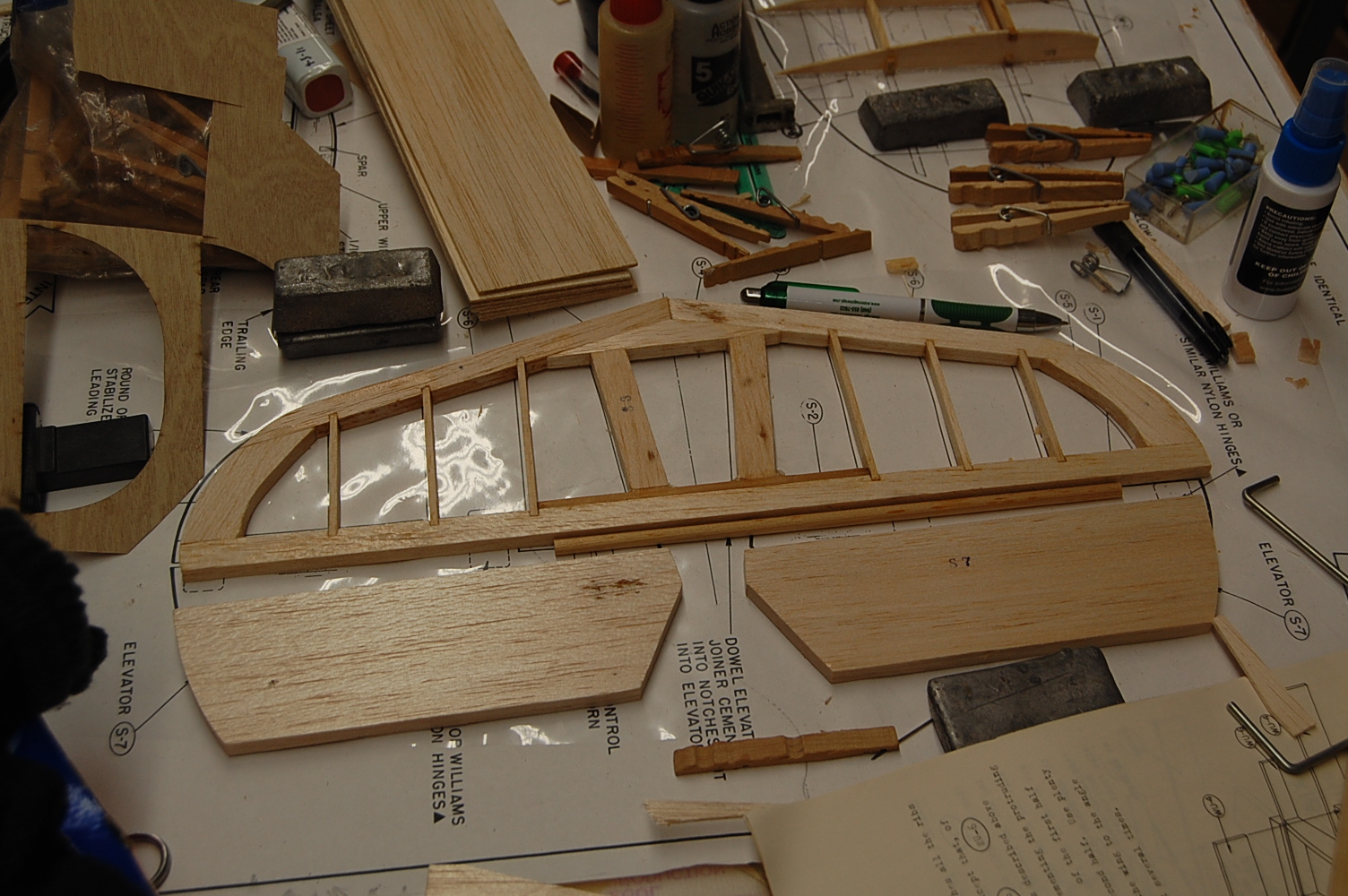
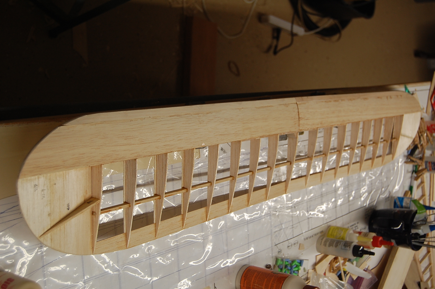
I haven't posted in a couple of days but in the mean time I have most of the upper wing framed up. I'm building a more scale like wing with no dihedral on the upper wing. Other than adding the ailerons, it's pretty much a standard "D" tube wing. You can also see where I have engineered space for ailerons. Before I wrap up the sheeting and cap stripping I will have to install some mounting blocks fore and aft to bolt down the wing. The wing tips add about four inches to each wing tip and are raised by the thickness of the wing. This will add some dihedral effect. I am planning on adding a small amount of dihedral to the lower wing but not nearly so much as the kit was designed with. The plans and instructions don't specify how much diehdral there should be but they show about ten degrees of dihedral on the drawings and if one used the included dihedral braces it would be more like twelve degrees. It seems a lot, even for a three channel design but if built with the stock parts each wing tip would be two and a half inches off the table at the outermost rib. I am currently shopping for some 40 to 50 oz torque mini servos to go in the upper wing.
08-04-2016 | 08:28 AM
#8

My Feedback: (6)
I just found your build Matt and I must say you are making great progress. The design looks to be the typical building crutch design used by other scale designers like Dick Katz. I have a set of plans for the old Royal design and was fortunate to know an old builder, now passed on, that built a number of Staggerwing designs over several decades. In conversations with him he warned me away from building the Royal as designed. He found when he built his 4th Royal Staggerwing he could greatly improve the way it flew and fit in retracts by increasing the wing thickness by 14%. I realize its a little late for your build but should you one day build another or decide to make new wings you might take this into consideration. Whenever I get to the point I want to built the Staggerwing I will take his warnings to heart. Right now its way down the list on airplanes to build but I do have a an Ace Simple Series Staggerwing I may build before then for a little casual flying. Sometimes you just need a quick easy build to recharge the old batteries.
Mike
Mike
08-04-2016 | 06:03 PM
#9
Thread Starter
Hi Mike, I actually built the Simple Series Staggerwing a decade or so ago. It's a pretty quick build. I got to maiden mine but lost it shortly thereafter to an engine out crash so I can't really say much about it. There is an electric foamie Staggerwing that has retracts. It is smaller than the Aristocraft so I know it can be done. On the real aircraft the fuselage frame work reaches down into a kind of extended wing root that mounts the entire landing gear. I suppose you could engineer a lower fuselage landing gear assembly with plug in lower wings. I'm not really looking for a lot of scale fidelity here. It will be a sport flier that has a pretty good resemblance to a Staggerwing.
08-04-2016 | 06:36 PM
#10
My Feedback: (6)
Matt, back the March 1974 issue of American Aircraft Modeller Ken Willard published a build article called Sunday Fighters. It was a .10 OS Max powered airplane designed to use Ace Simple Series constant cord foam wings. The plane could be built to resemble a German or British WWI biplane.(Article was posted here at my request http://www.airplanesandrockets.com/a...march-1974.htm ) In 1974 I ordered the plans and built one. I wanted to build the German flavor but tried using this new CA Glue on the foam wings only to discover it melted the foam. I quickly beveled the damaged ends to match the British design and built the British flavor. The last time I looked the foam cores are available again from an Ebay store, the plans are on AeroFred.com or outerzone.co.uk. I downloaded the plans an at some point will order two sets of wing cores.
Mike
Mike
08-15-2016 | 07:01 PM
#11
Thread Starter
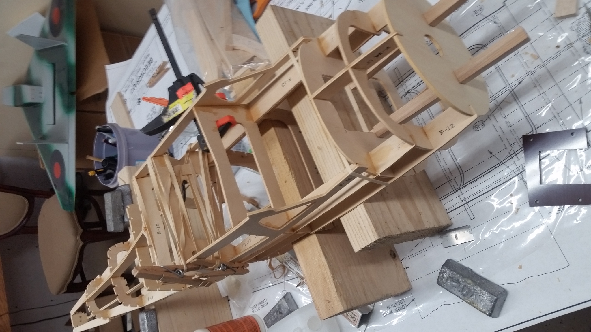
Had a nice vacation taking the waters in Pagosa Springs, CO. If you ever go there, the hot air balloon ride is so worth it. I didn't get to see it up close but it looks like they have a nice RC field there. Back to the build though. Before I left, I glued up the stabilizer. Since returning I have been working through building the lower wing. This model was designed with out ailerons so there is a ton of dihedral, There is about two inches under the outermost wing rib plus another three fourths of an inch from the tapered wing tip. As nearly as I can figure it would have been about five degrees under each wing tip. The wing center braces were cut at a ten degree angle. I cut new braces at about two degrees. One of the dihedral braces is pretty long spanning the entire width of the landing gear. The gear blocks in the lower wing glue directly to it. This brings me to the biggest part error so far. The kit comes with six plywood rib doublers that help support the landing gear blocks. The cutouts for the gear blocks weren't square and they were cut to fit as though the dihedral braces weren't there. After removing the marked area they epoxied in just fine. With these, the dihedral brace and some triangle stock, the landing gear should be plenty sturdy. I also placed three sixteenths play plates in the bottom of the center line front rib bays. It doesn't show up much in the picture but it will support the mounting bolts That will replace the rubber bands for mounting the wings. The next step will be finishing sheeting and cap stripping the wing and adding in some additional stock for the rear mounting bolts. Once the wings are all buttoned up I can go back to the fuselage. I expect it to take a fair amount of fetteling to get everything square and symmetrical. The instructions don't really say much about alignment aside from centering the wing relative to the fin. The plans show, relative to the aircraft center line, engine down thrust, Identical positive angle of attack on both wings and a lesser positive angle on the stabilizer. Effectively this give an angle of attack of about 2 degree but as is often observed, plans and the actual kit as cut don't necessarily agree. The stabilizer has its own mounting blocks and I haven glued in the lower wing saddle yet so the next big phase will be alignment.
08-16-2016 | 05:35 AM
#12
My Feedback: (6)
It seems the rule thumb that minor discrepancies are to be expected on such and old kit/design. I was amazed how much variance there is on fuselage formers when I sent a set of plans hand drawn in the precomputer days to a laser cutter. He would cut each former drawing in half and flip one side over the other half to compare and then correct the two sides to match on every one of them.
08-16-2016 | 07:37 AM
#13
Thread Starter
It seems the rule thumb that minor discrepancies are to be expected on such and old kit/design. I was amazed how much variance there is on fuselage formers when I sent a set of plans hand drawn in the precomputer days to a laser cutter. He would cut each former drawing in half and flip one side over the other half to compare and then correct the two sides to match on every one of them.
08-16-2016 | 08:23 PM
#15
Thread Starter
It would be interesting to compare my build with a laser cut kit. Aside from the conveniences that come from laser cutting I think it would come out lighter. This kit has a lot of three ply plywood that is heavier than lite-ply. I think in some cases you could use balsa even. I'm not too worried about the weight though, as it has a pretty generous wing area. I didn't get a lot done today due to working on the kids cars and mowing on the pasture.
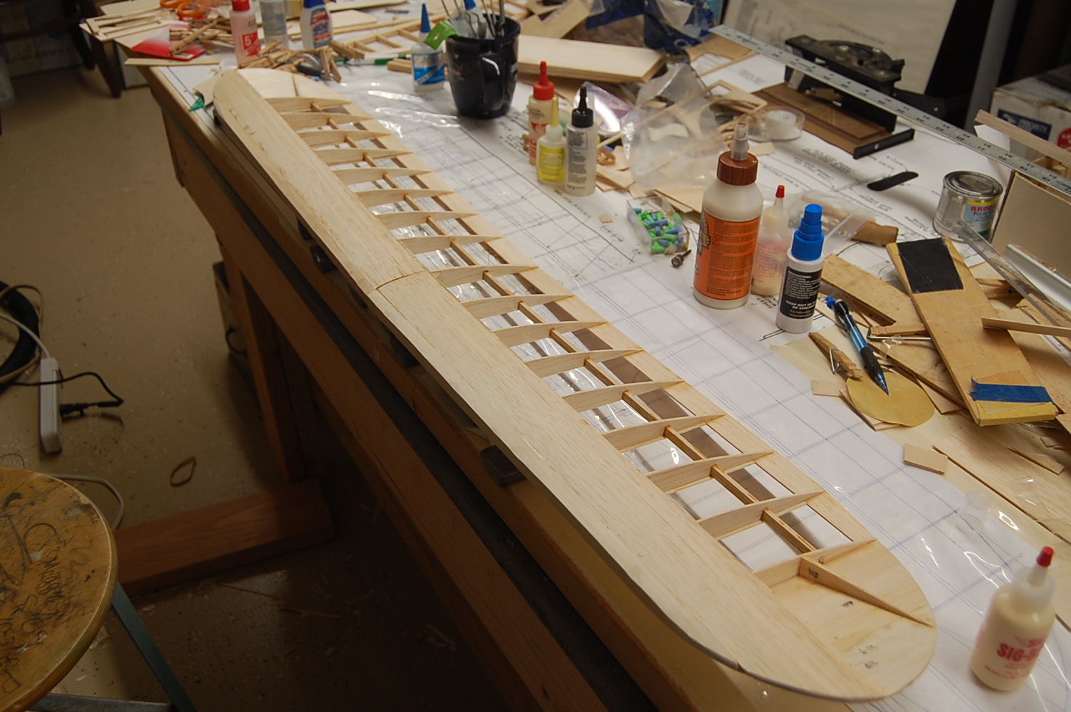
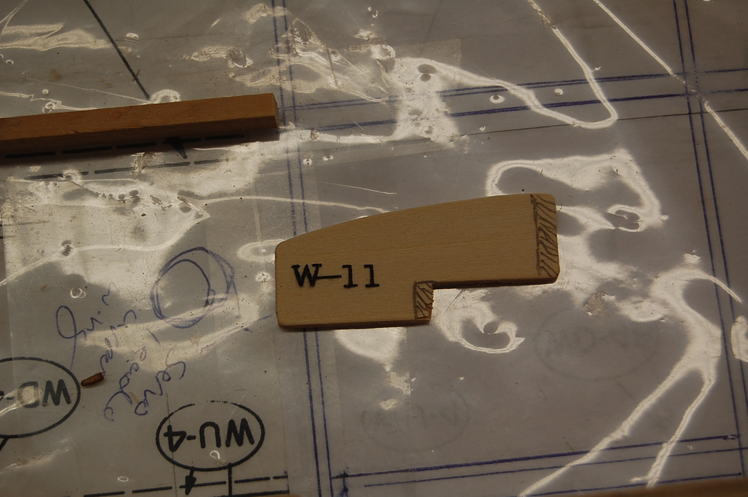
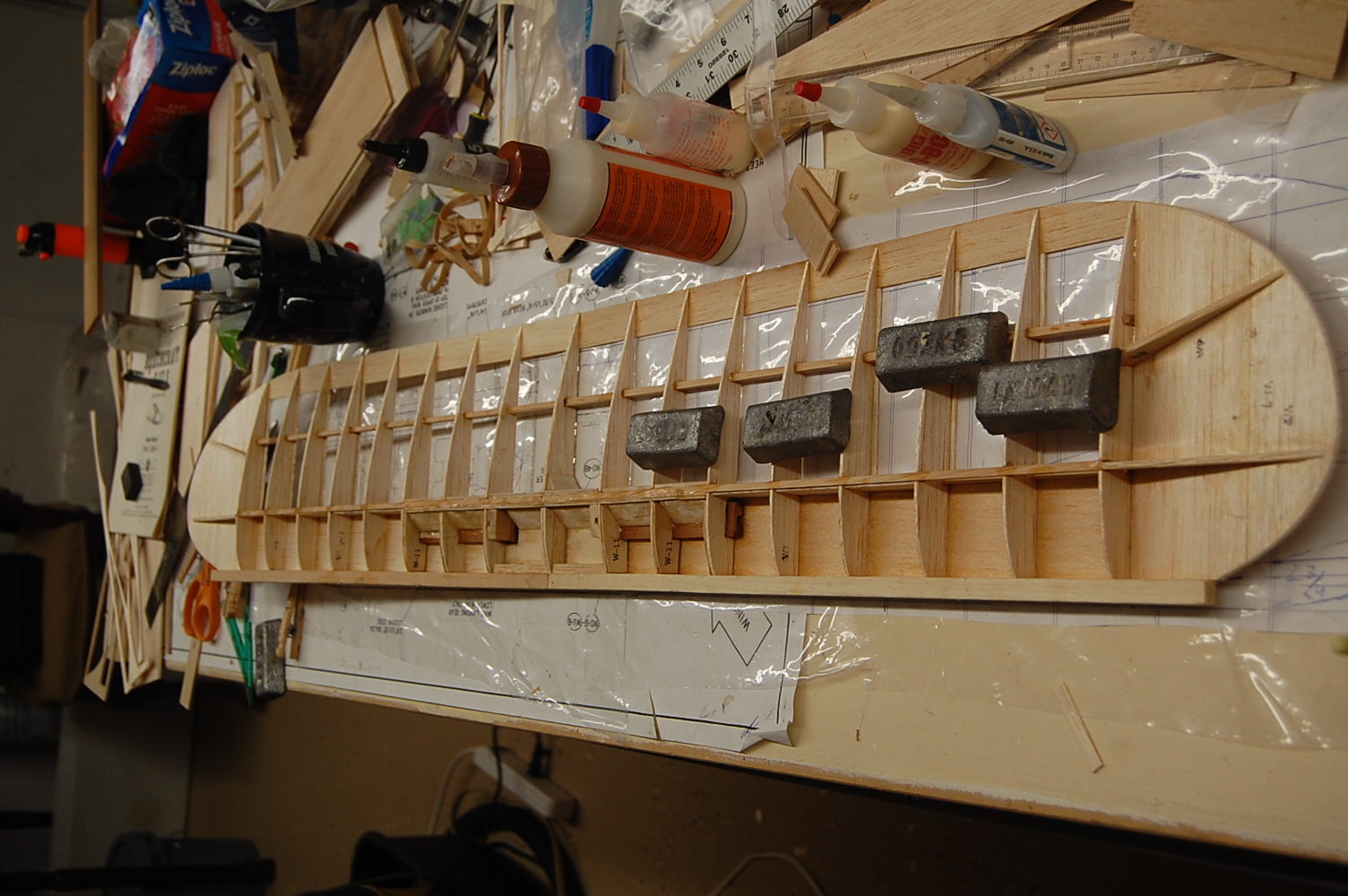
The first picture show the slots cut in the lower wing to give access to the landing gear blocks. The second picture shows a deviation from the plans. W8, the aft wing tip brace was moved forward a bit so that it didn't stick up above the tip rib and then swept back to match the tip of the wing. The wing tip is sheeted and it gives a smooth wing tip this way. The other two picture just show the leading edge sheeting. The wing on this airplane is a pretty standard built up wing with sheet from the leading edge back to the spars and cap strips and a sheeted center section. There are shear webs on the spars and the dihedral brace on the lower wing extends outboard of the landing gear. The brace could probably function as a spar all on its own. The actual spars are "Japanese Cyprus". This appears to be a hardwood. Even after all these years the spars were still straight and distortion free.
The first picture show the slots cut in the lower wing to give access to the landing gear blocks. The second picture shows a deviation from the plans. W8, the aft wing tip brace was moved forward a bit so that it didn't stick up above the tip rib and then swept back to match the tip of the wing. The wing tip is sheeted and it gives a smooth wing tip this way. The other two picture just show the leading edge sheeting. The wing on this airplane is a pretty standard built up wing with sheet from the leading edge back to the spars and cap strips and a sheeted center section. There are shear webs on the spars and the dihedral brace on the lower wing extends outboard of the landing gear. The brace could probably function as a spar all on its own. The actual spars are "Japanese Cyprus". This appears to be a hardwood. Even after all these years the spars were still straight and distortion free.
08-17-2016 | 07:06 AM
#16
My Feedback: (6)
Looking good Matt! I have been trading emails with Eddie over at Lazer-Works in Wichita Falls and you will be glad to hear he is watching your build so they might improve their own parts (short) kit. The package includes the formers, ribs, and anything on the plans that would have to be cut to a certain shape, price is TBD. They are also planning on offering a cowling and plans, two pages, plus instruction paperwork will be available.
08-17-2016 | 08:27 AM
#17
Thread Starter
Thanks. I stopped in at his shop yesterday to buy some epoxy and he was working on it. He does some other laser cutting/etching but the short kits are a big product for him.
08-17-2016 | 08:56 PM
#19
Thread Starter
Edit: looking at this it seems a little curt. I just meant it as an explanation that he makes a quality product.
Last edited by mgnostic; 08-17-2016 at 09:43 PM.
08-17-2016 | 09:37 PM
#20
Thread Starter
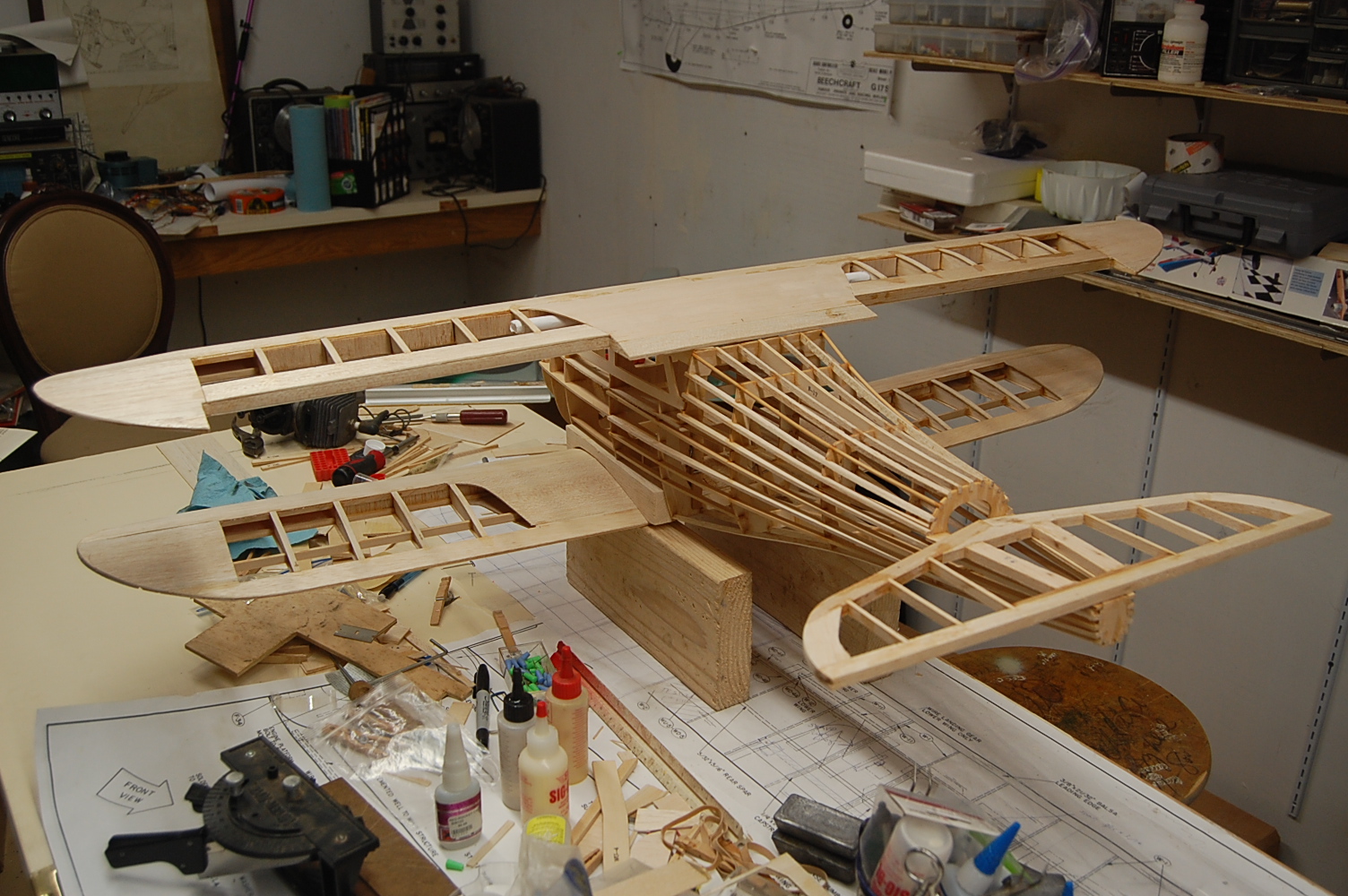
I didn't accomplish a lot of dramatic stuff today but the wings are mostly sheeted and capstripped now, I just had to stack the wings and fuselage to see how it would look. The leading edges aren't shaped yet and the saddle for the stabilizer isn't installed either but you get an idea of the shape. Even in the bare bones it has a robust quality to it.
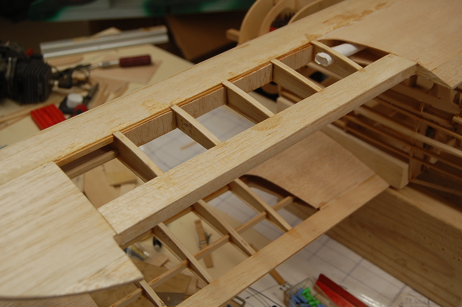
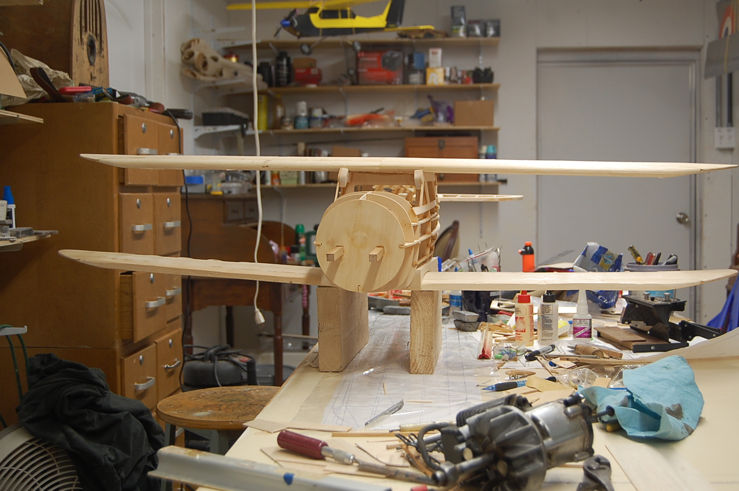
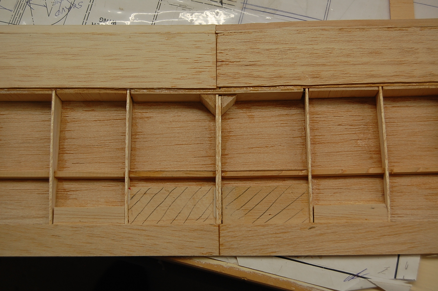
In the first picture you can see where I have added structure for the ailerons. I used the same one inch by one-sixteenth sheet as was used in the trailing edges. There is no shaped trailing edge stock used in the kit as designed. The trailing edge is just a one inch wide strip above and below the aft end of the rib. It is lightweight and as long as you aren't cutting ailerons or flaps out of it, it seems just fine. Where I see it as a problem is that if building a stock kit, i don't think the trailing edge would hold up very well under a stack of number 64 rubber bands. Since I am building a bolt on wing I simply filled in the area between the upper and lower trailing edge with some shaped trailing edge stock. I did this to the two inner rib bays. This should firm up the area
I did this on both the upper and lower wing. Reaching a point where I can mock up the wings was satisfying but it brings to light a couple of issues. One glaring item is that the upper wing just sort of sits on top of the fuselage. There is a step from the trailing edge the top of the fuselage. I expect that I will build up the top edge of the F-10 former that forms the aft wall of the cockpit and then use some balsa to fair the stingers so that it is all even with the trailing edge of the wing. The manual only shows one photo of what is supposedly the completed model. There is little if any dihedral in the model in the photo, certainly way less than the model would have if built according to plan. It is a very grainy photo but it shows the wing fairing smoothly into the fuselage and although there are rubber bands on the wing you can't see any parting line between the wing and fuselage. It looks to be all of a piece, possibly a U/C model? At any rate, next step for the wings include fabricating servo mounts in the upper wing and mounting the tabs for the wing struts. When those are in place I can do the last few capstrips. Before I called it a night I took a moment to mock up one of the wing struts. In profile they look good but they are made such that the strut and the fairing just stack one on top of the other and then bold through the wing strut tab. The whole strut assembly is made from the heavy three ply. I kind of suspect that in practice one would have not flown with the struts, If one were to drag the tip of the rubber band mounted wing I imagine the weakest link would be the balsa wing rib. Since I have been making some running changes to this kit anyway I think I will probably work over the strut design so they are more aesthetically pleasing and possibly a few grams lighter.
08-19-2016 | 09:13 PM
#22
Thread Starter
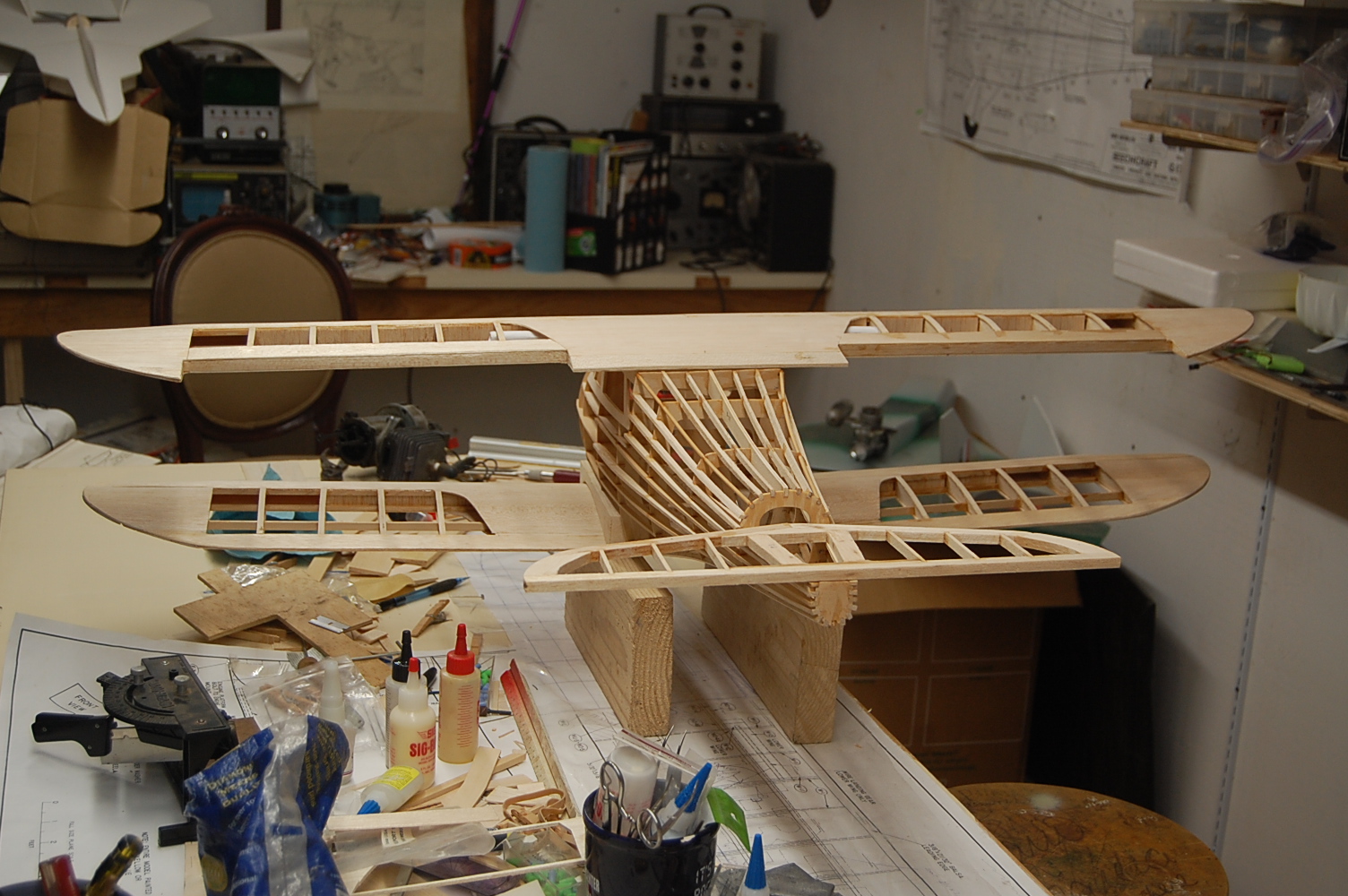
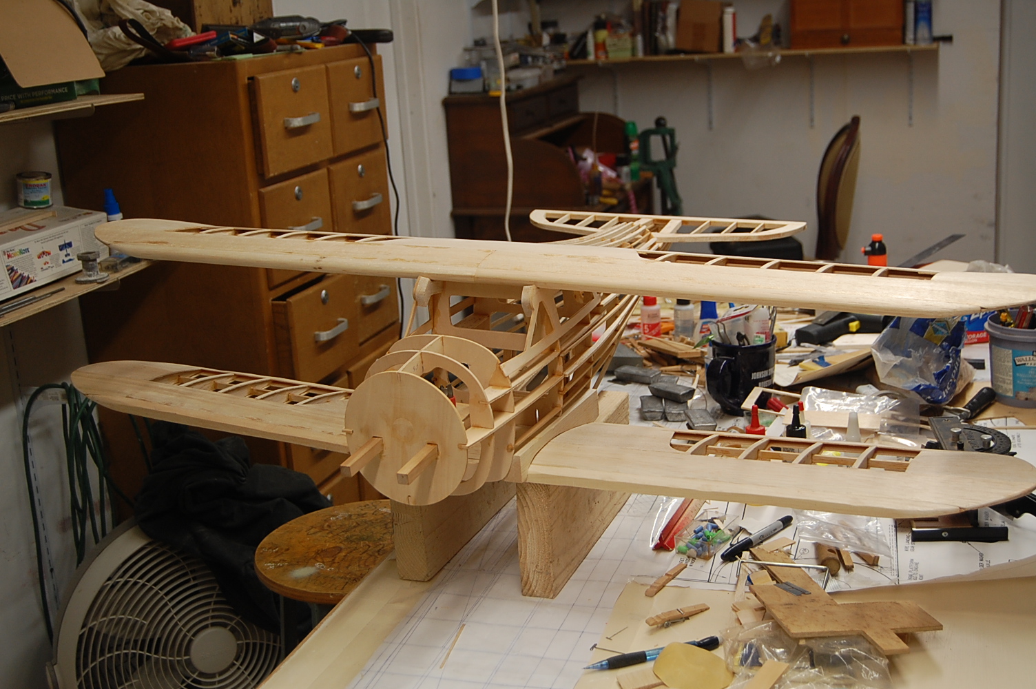
The accomplishment for this session was bolting down the upper wing.
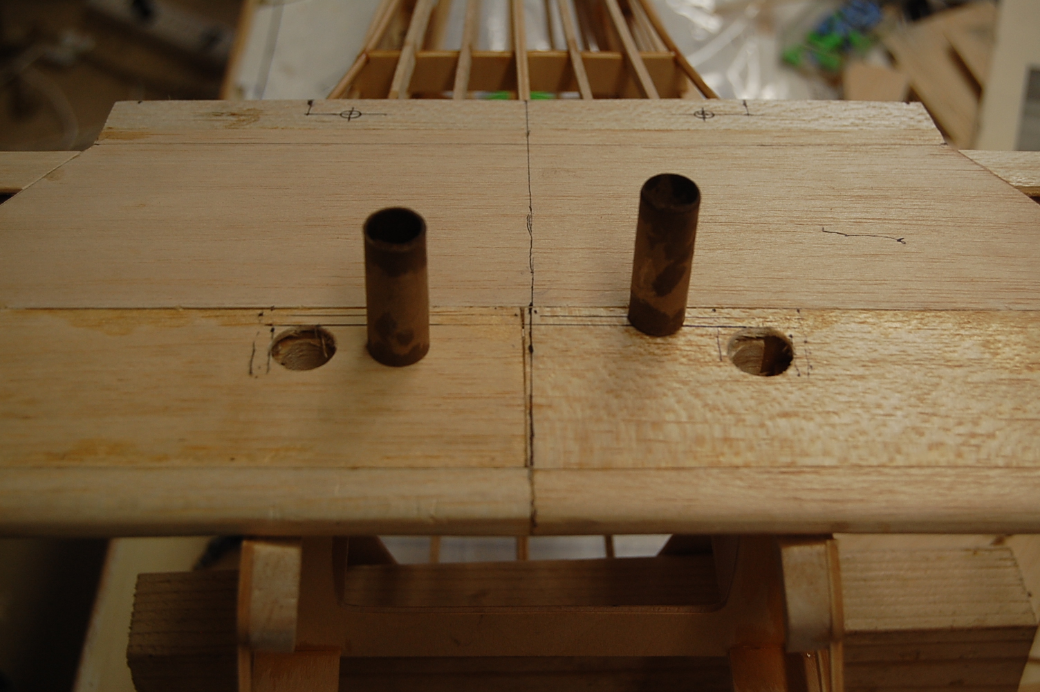
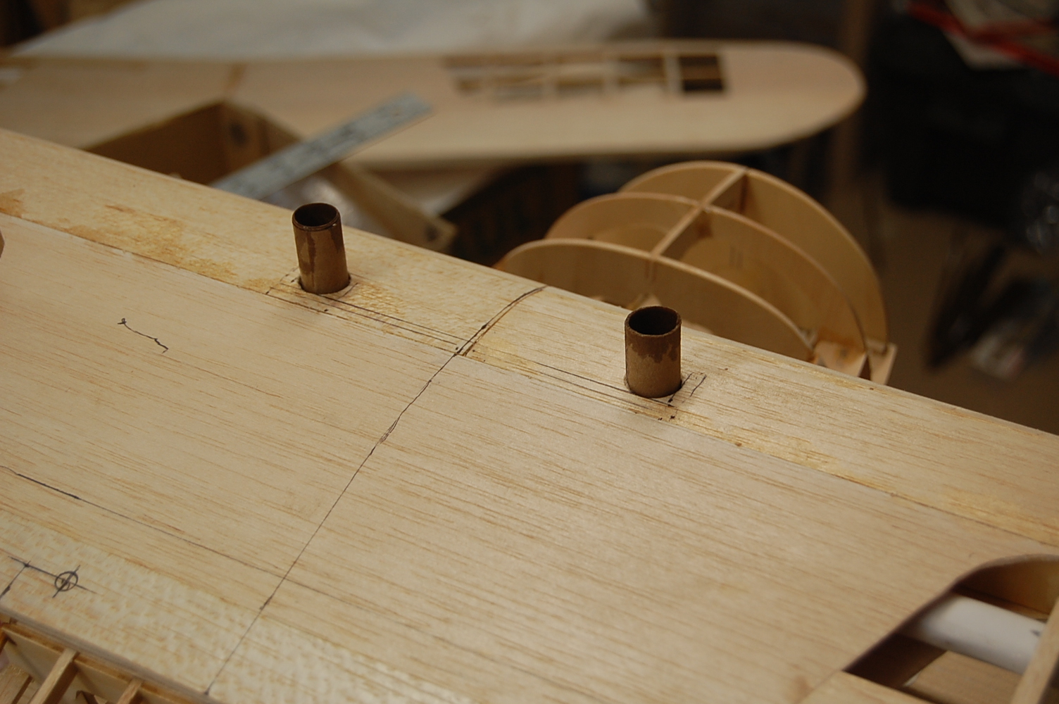
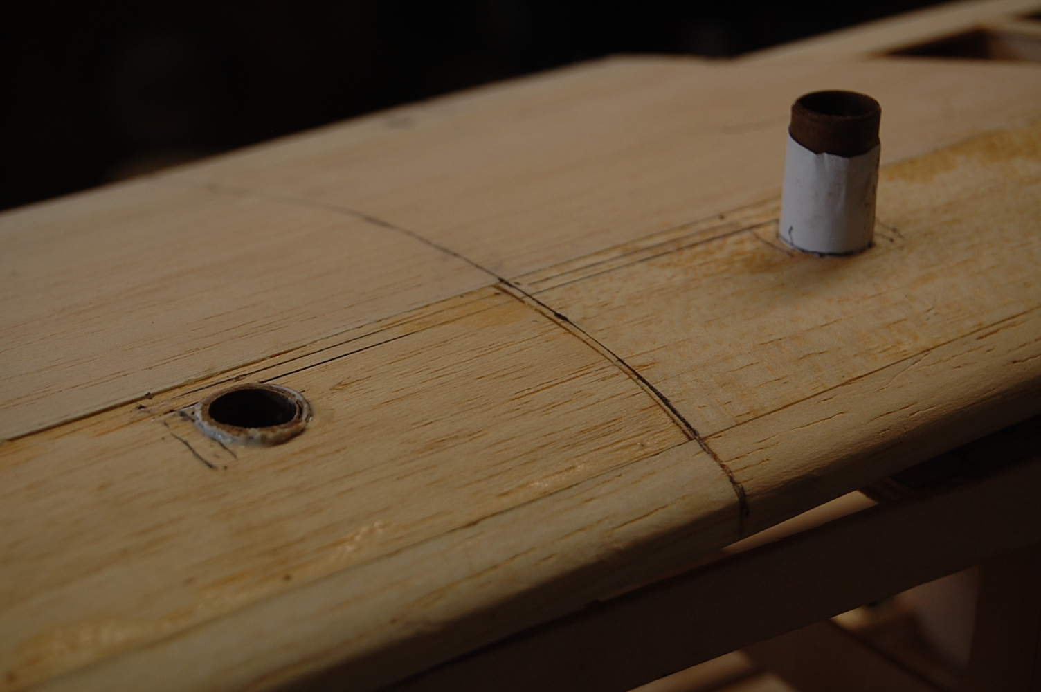
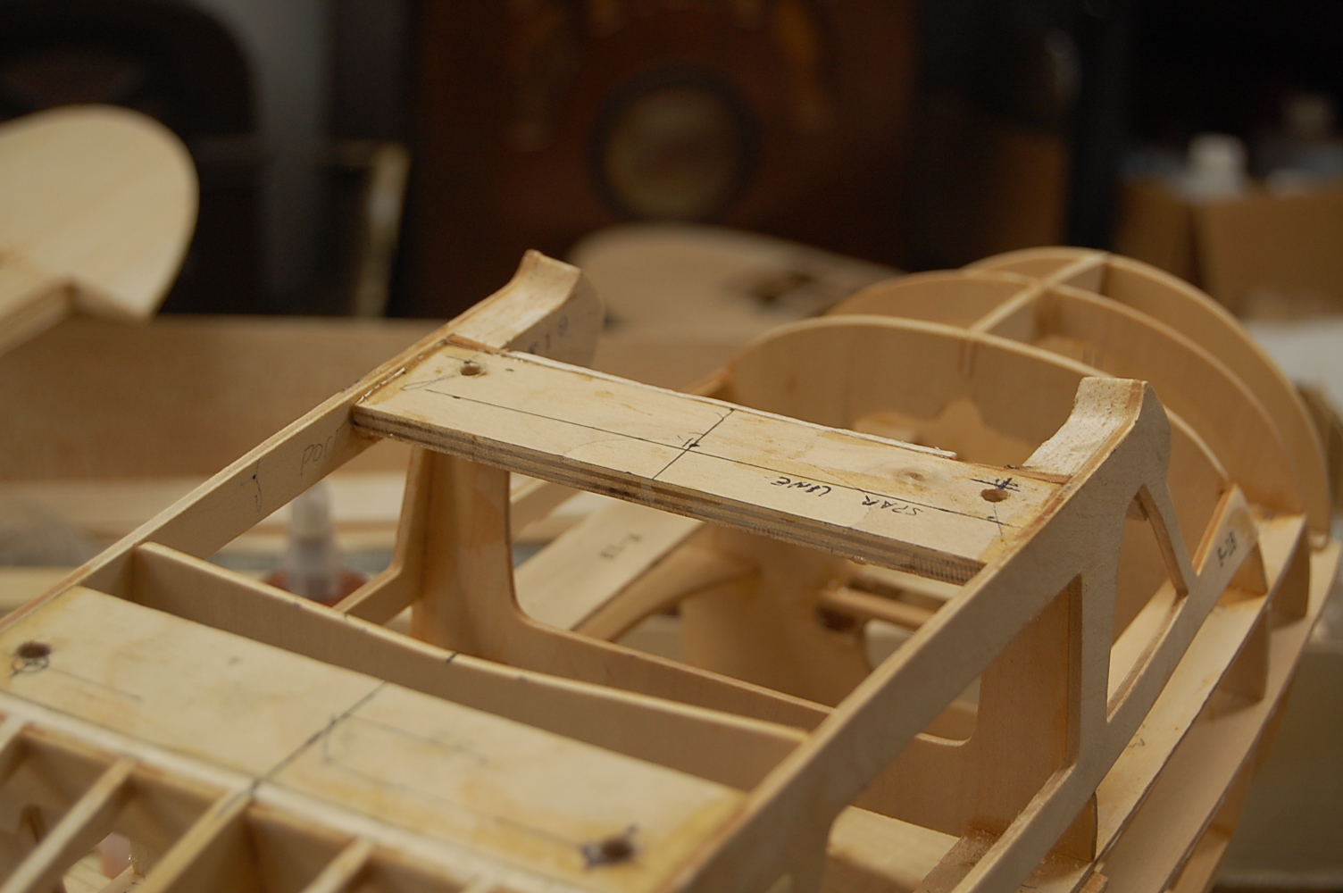
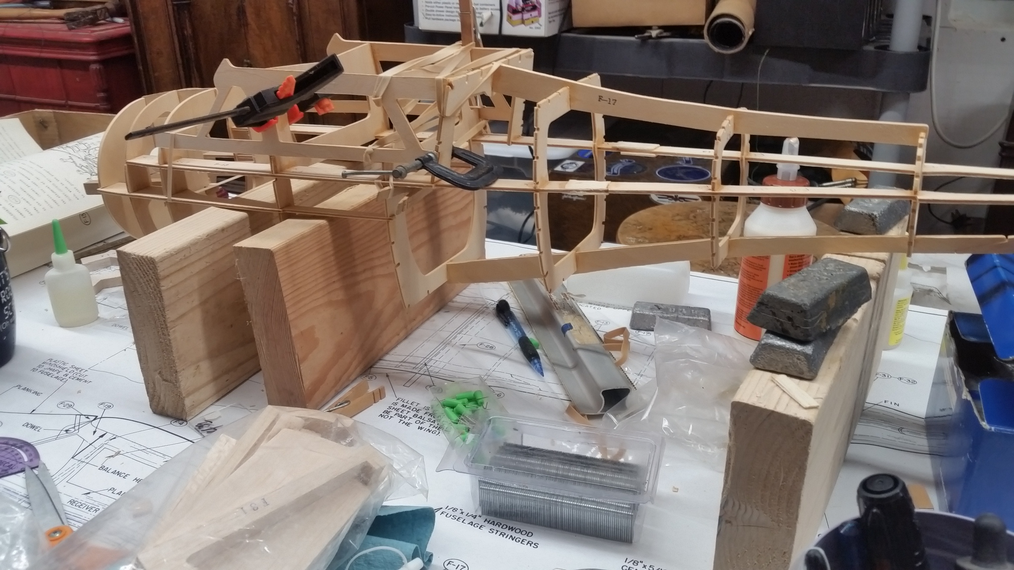
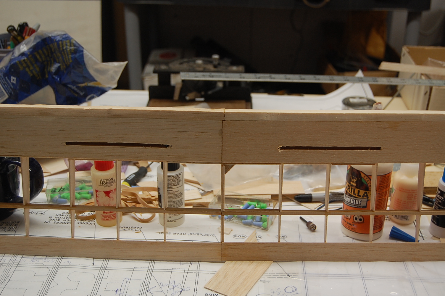
Ordinarily mounting wings on a model like this occurs closer to the end of a build. However, the instructions don't give a lot of guidance beyond "install the lower wing saddles" when building the fuselage. The design is such that the saddles could be installed so that the lower wing could easily have several degrees more or less incidence than the upper wing. Given that we are working with flat bottom wings, you could probably eyeball the lower wing mount and get it close enough to have an airplane that would fly...more or less. The plans, for what it's worth, show the wings having the same angle of attack. This is probably a pretty safe bet and the plan I am going with. To accomplish that I want a fixed point of reference and since the upper wing sits flat on the fuselage that seems a good place to work from. Models this size often use two 1/4-20 nylon screws in the trailing edge and a peg or two in the leading edge. but there much structure in the upper fuselage for a peg to inset into so I put mounting plates in the wing ahead of the spar and then I epoxied 1/4 inch ply into the fuselage structure which was than drilled and tapped for the 1/4-20 screws both for and aft. I cut the plates 1 inch wide but could have saved some weight by cutting them only 3/4 inch wide. As cunning plans are want to do, this one ran into a complication that required a little planning. The first former under the wing (F-4) falls such that If I put the forward mounting plate in front of F-4 it puts with wing bolts way up into the leading edge. Placing the plate behind F-4 allows the wing bolts to fall between F-4 and the wing spar. Seems like the strongest way to do things so I went with it. I made some nice cardboard tubes to neaten things up and to support the upper wing sheeting. This went well until I opened up the holes for the tubes. It was than that I saw that the triangle stock that I used to tie the wing plates to the spar stuck out halfway across the space where the tubes were supposed to go. This was resolved by using a forstner bit in my little drill press. I set the stop so that the bit would just graze the mounting plate and ran the bit down into the wing. This trimmed way the triangle stock and left a nice flat space with a pilot hole for the wing bolt. Then I could glue in the tubes which will eventually be sanded flush with the wing surface. The fourth and fifth photos show my reference points for squaring up the wing. With rubber bands you could scoot the wing around to suit but with four wing bolts I wanted to get it right. I established the center line of the wing measuring in from the tips and then measure back out for reference points to square the wings. I pinned the wing to the center line of the fuselage and used tried and true method of setting the wing tips equidistant from the center line. I completed one mounting hole, snugged the wing down and then rechecked the alignment before drilling the rest of the holes. The mounting holes were completed by tapping with a 1/4-20 thread, flooding the thread with CA clue and then tapping again. With the wing mounting plates in the upper part of the cockpit is sufficiently well tied together that I think I can probably remove the upper portion of the F-5 former. This would improve access to the interior of the fuselage. I think I will wait until after the fuselage sheeting is done since it can be cut out at any point up until the windows are installed.
Ordinarily mounting wings on a model like this occurs closer to the end of a build. However, the instructions don't give a lot of guidance beyond "install the lower wing saddles" when building the fuselage. The design is such that the saddles could be installed so that the lower wing could easily have several degrees more or less incidence than the upper wing. Given that we are working with flat bottom wings, you could probably eyeball the lower wing mount and get it close enough to have an airplane that would fly...more or less. The plans, for what it's worth, show the wings having the same angle of attack. This is probably a pretty safe bet and the plan I am going with. To accomplish that I want a fixed point of reference and since the upper wing sits flat on the fuselage that seems a good place to work from. Models this size often use two 1/4-20 nylon screws in the trailing edge and a peg or two in the leading edge. but there much structure in the upper fuselage for a peg to inset into so I put mounting plates in the wing ahead of the spar and then I epoxied 1/4 inch ply into the fuselage structure which was than drilled and tapped for the 1/4-20 screws both for and aft. I cut the plates 1 inch wide but could have saved some weight by cutting them only 3/4 inch wide. As cunning plans are want to do, this one ran into a complication that required a little planning. The first former under the wing (F-4) falls such that If I put the forward mounting plate in front of F-4 it puts with wing bolts way up into the leading edge. Placing the plate behind F-4 allows the wing bolts to fall between F-4 and the wing spar. Seems like the strongest way to do things so I went with it. I made some nice cardboard tubes to neaten things up and to support the upper wing sheeting. This went well until I opened up the holes for the tubes. It was than that I saw that the triangle stock that I used to tie the wing plates to the spar stuck out halfway across the space where the tubes were supposed to go. This was resolved by using a forstner bit in my little drill press. I set the stop so that the bit would just graze the mounting plate and ran the bit down into the wing. This trimmed way the triangle stock and left a nice flat space with a pilot hole for the wing bolt. Then I could glue in the tubes which will eventually be sanded flush with the wing surface. The fourth and fifth photos show my reference points for squaring up the wing. With rubber bands you could scoot the wing around to suit but with four wing bolts I wanted to get it right. I established the center line of the wing measuring in from the tips and then measure back out for reference points to square the wings. I pinned the wing to the center line of the fuselage and used tried and true method of setting the wing tips equidistant from the center line. I completed one mounting hole, snugged the wing down and then rechecked the alignment before drilling the rest of the holes. The mounting holes were completed by tapping with a 1/4-20 thread, flooding the thread with CA clue and then tapping again. With the wing mounting plates in the upper part of the cockpit is sufficiently well tied together that I think I can probably remove the upper portion of the F-5 former. This would improve access to the interior of the fuselage. I think I will wait until after the fuselage sheeting is done since it can be cut out at any point up until the windows are installed.
08-23-2016 | 09:02 AM
#24
Thread Starter
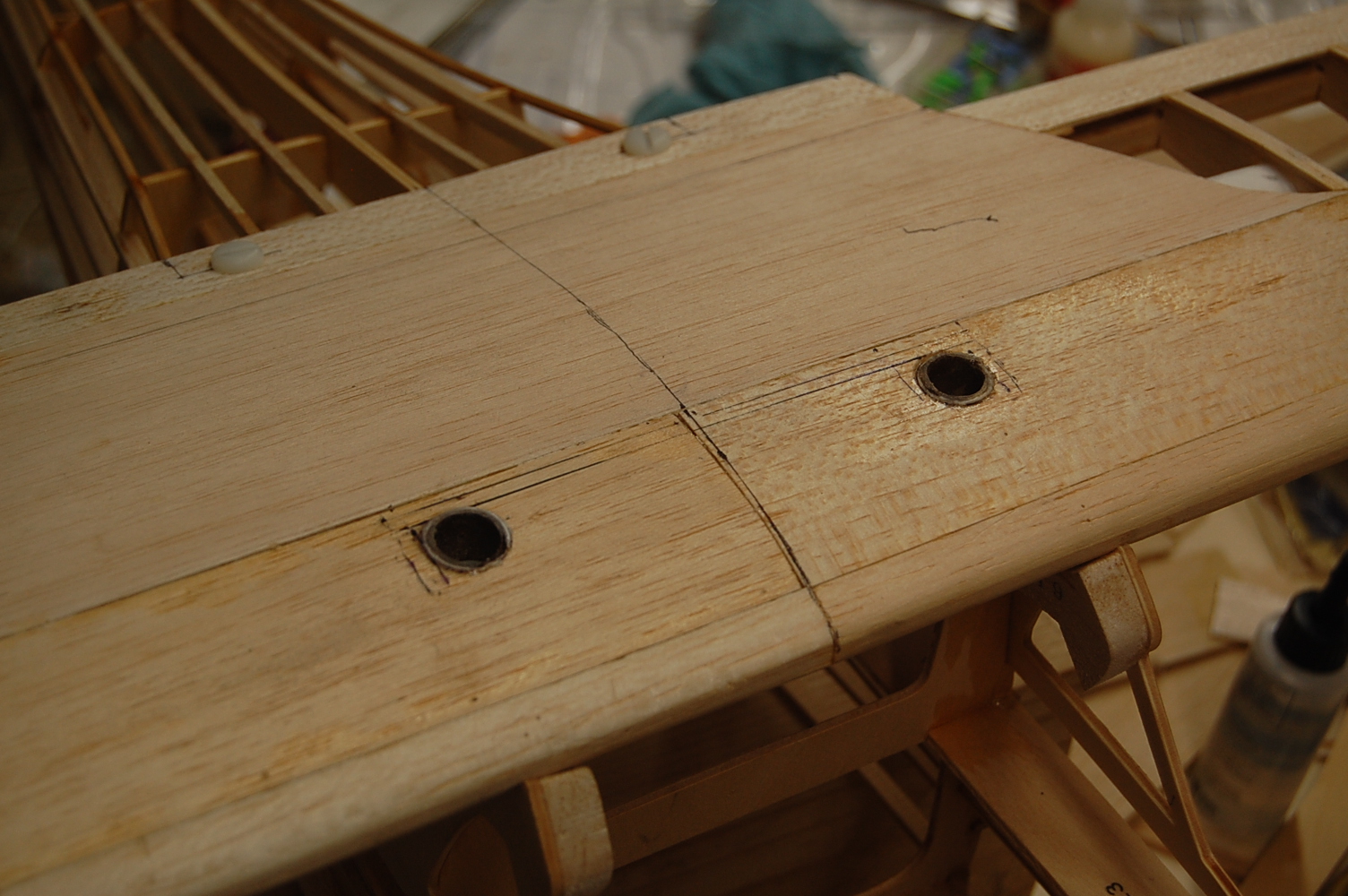
That sounds pretty spiffy. They are now sanded flush with the upper surface and are deep enough that it probably wouldn't take much friction to hold a plug in place.

