


TF Beechcraft Bonanza F33A Build
 12-29-2019, 02:50 PM
#626

Thread Starter
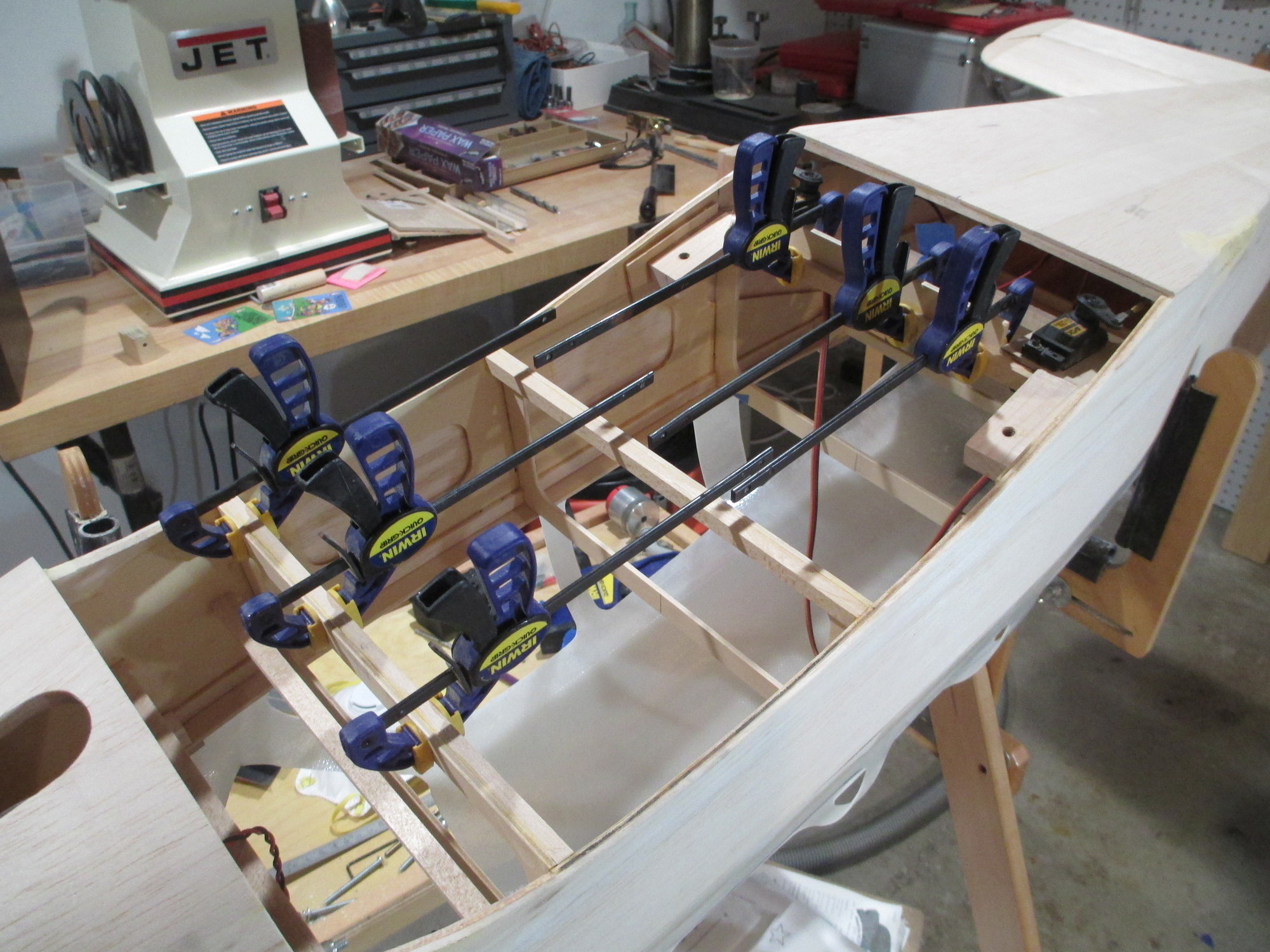
In preparation to removing the top portions of formers F3, F4, F5 and F6, I thought it wise to add structure to the bottoms of these formers for additional reinforcement beforehand. 1/4" x 3/8" basswood lengths were glued.
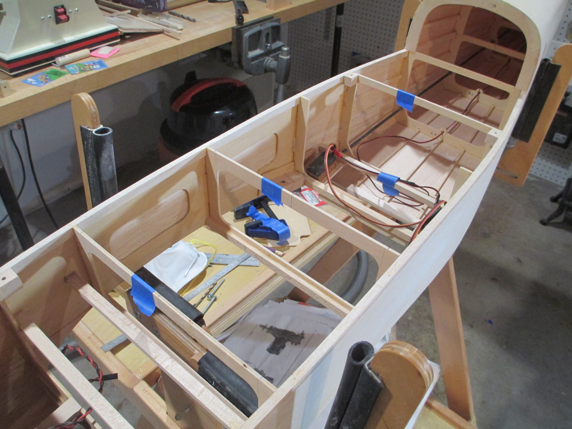
I've marked the tops of the formers that need to be removed with blue tape to make sure I don't accidentally take the wrong ones out!
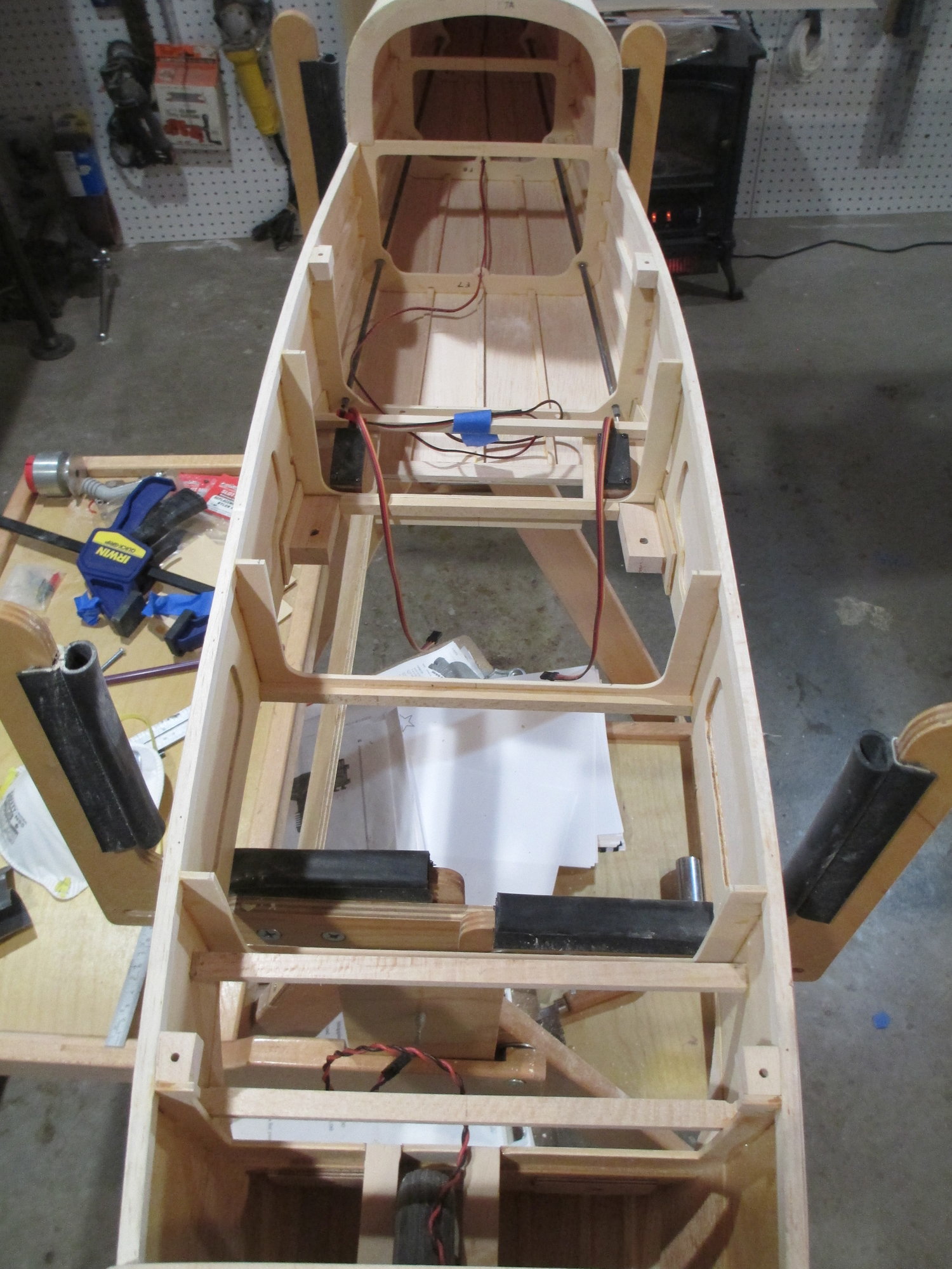
All the former tops have been removed...

 12-30-2019, 05:10 AM
#628
Thread Starter
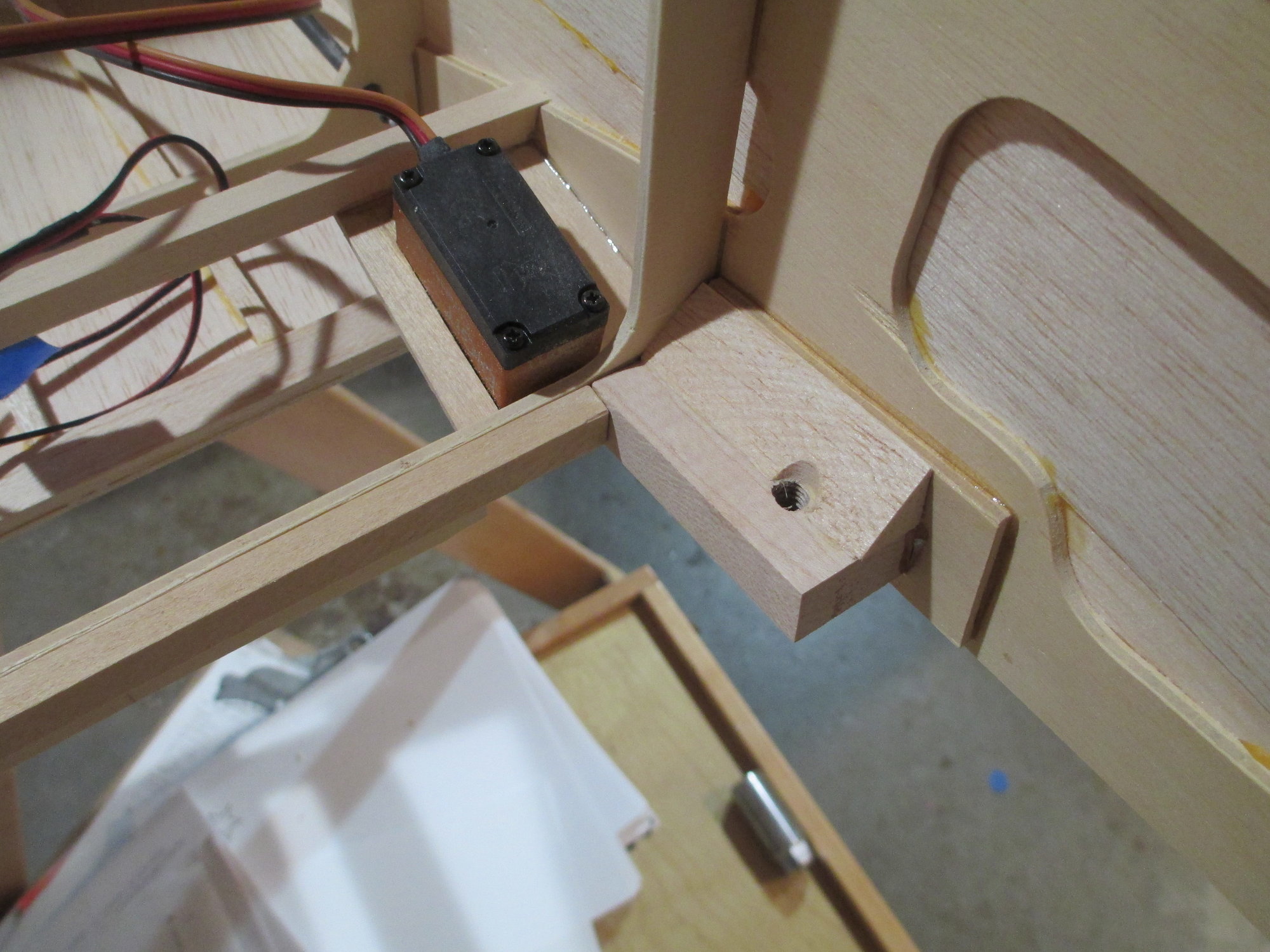
A small section of balsa tri-stock was added for additional support at each wing mount block.
1/4" tri-stock was also added to each former that had its top removed.
 01-01-2020, 01:01 PM
#630
Thread Starter
I have many tasks started, but to keep this project moving ahead that's what needs to be done. My OCD is wreaking havoc with me though!
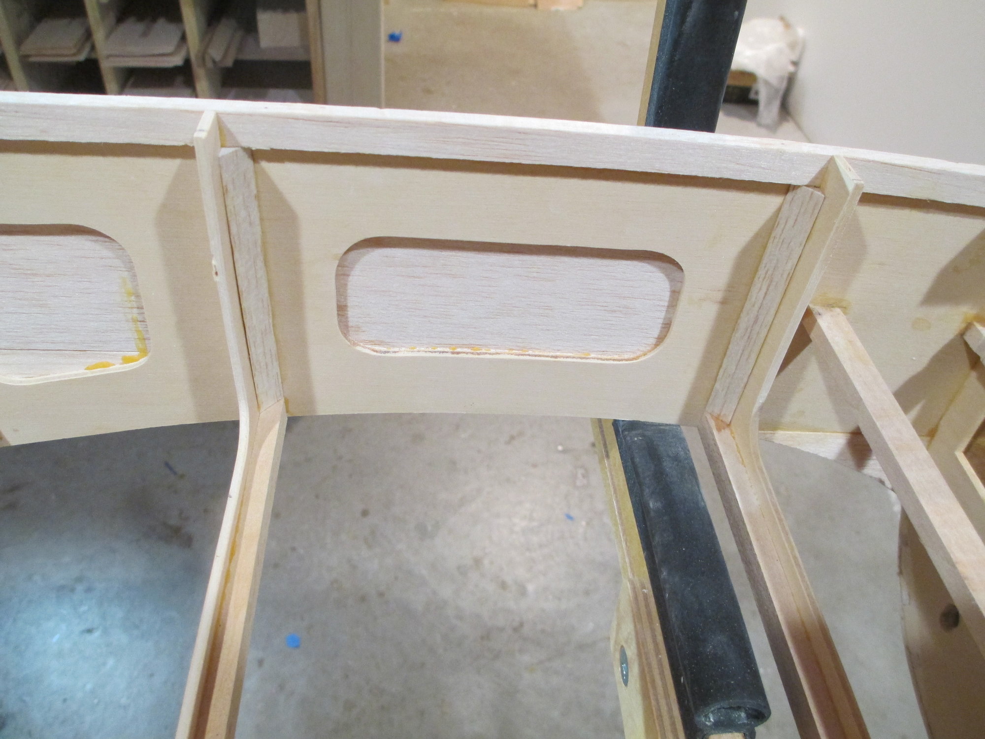
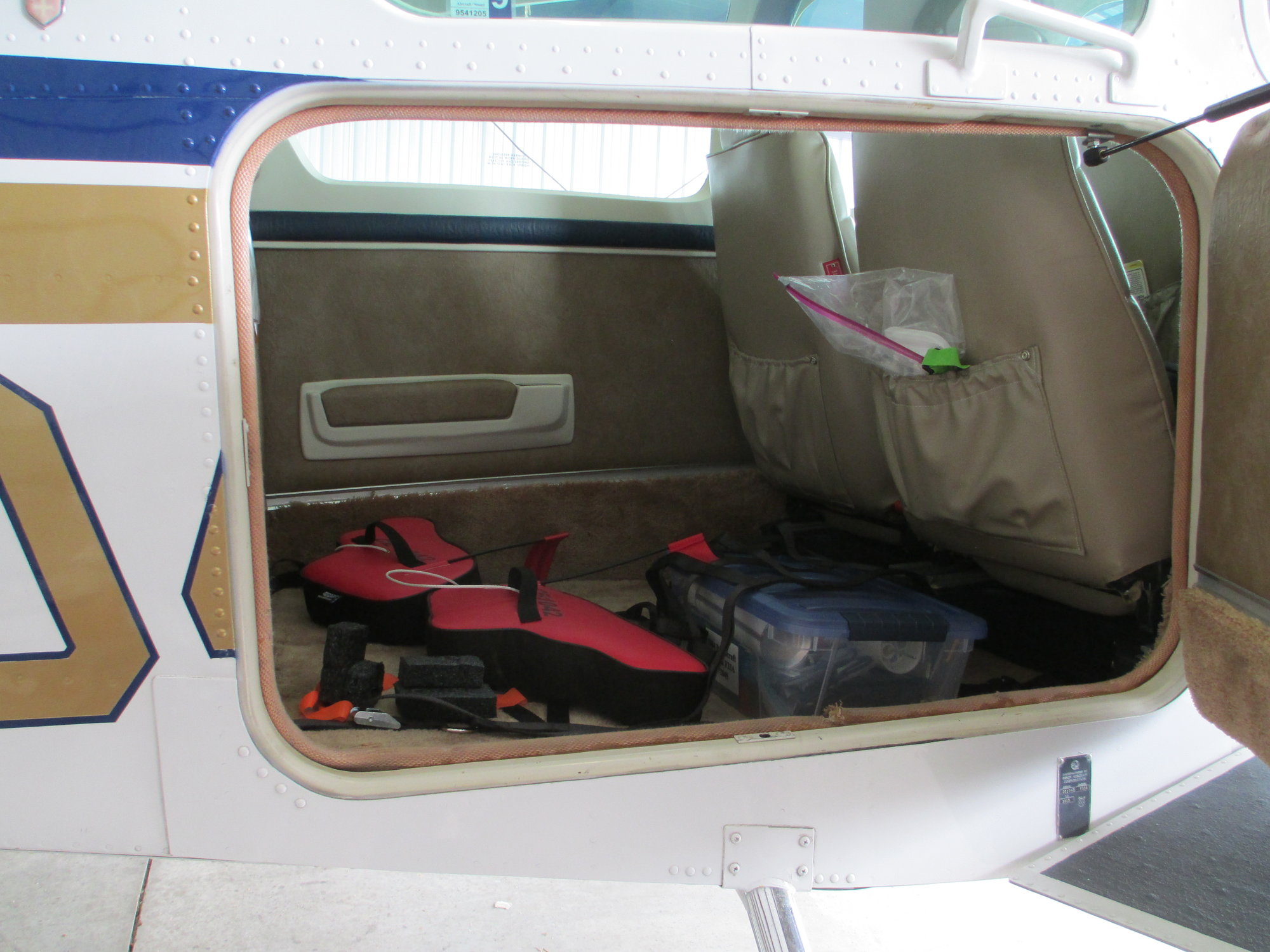
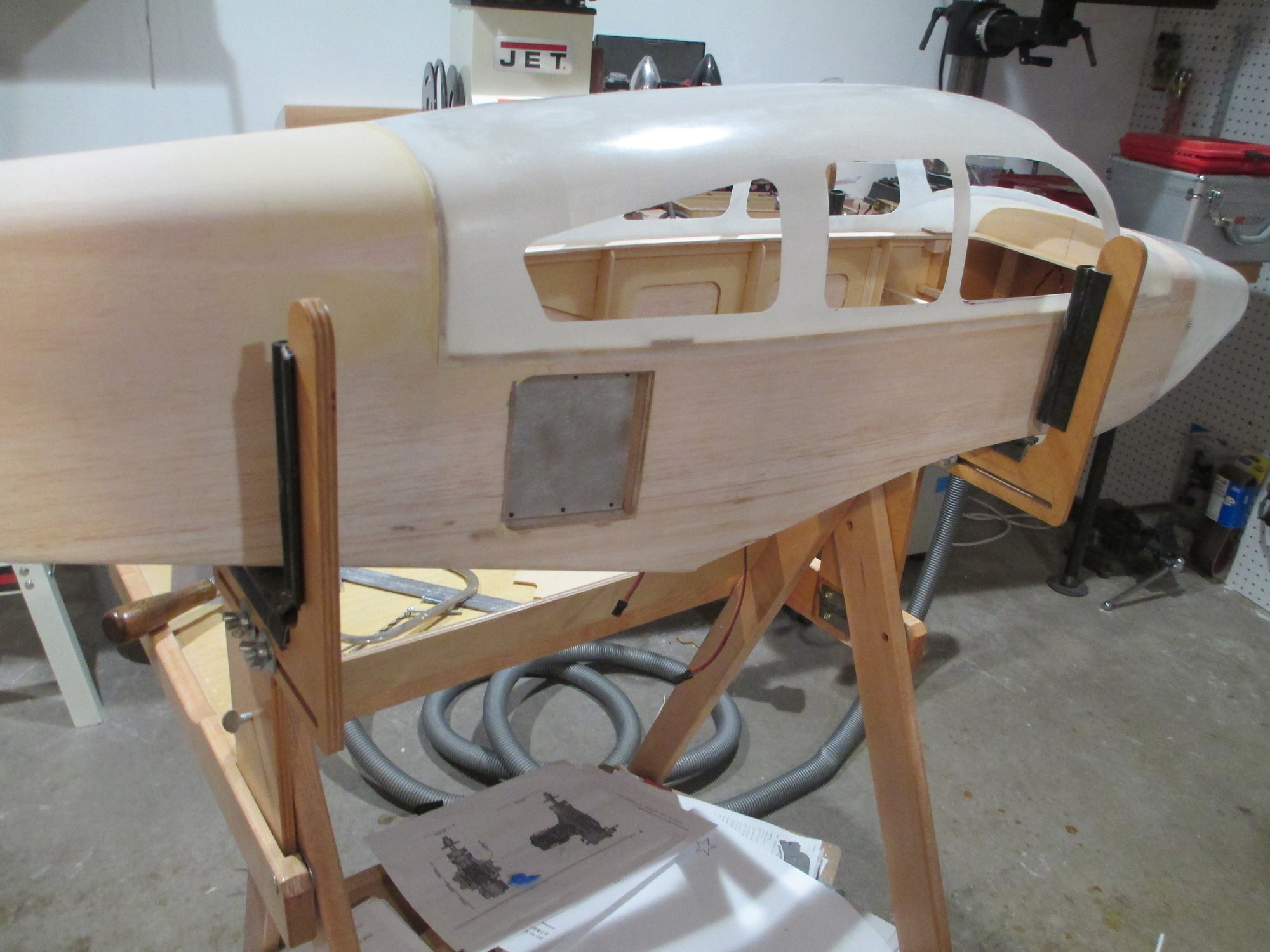
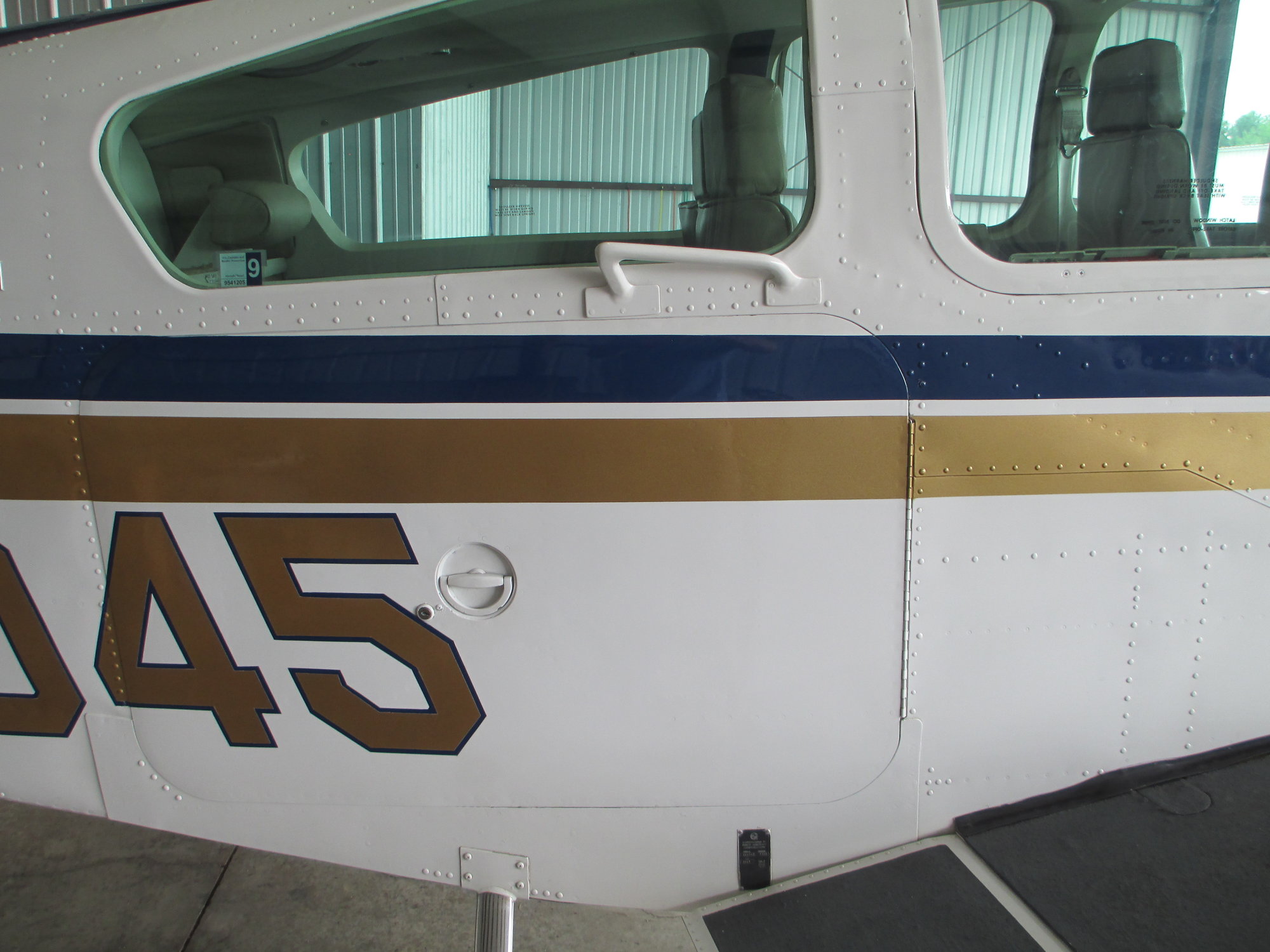
It was a little unnerving to cut an opening into the side of this fuselage, but it was part of the master plan. While the baggage opening is much smaller, a larger door will create the illusion of something more true to scale. The full scale Bonanza would have had an optional 22 x 37 inch baggage door to access a 35 cubic foot, 270 pound capacity cargo area.
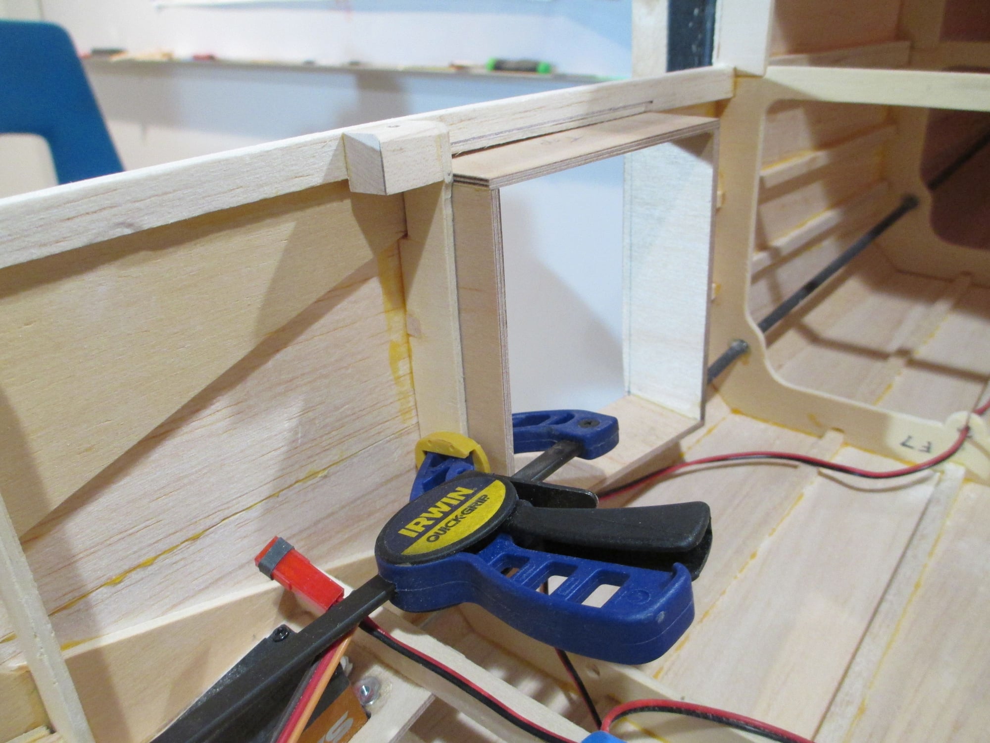
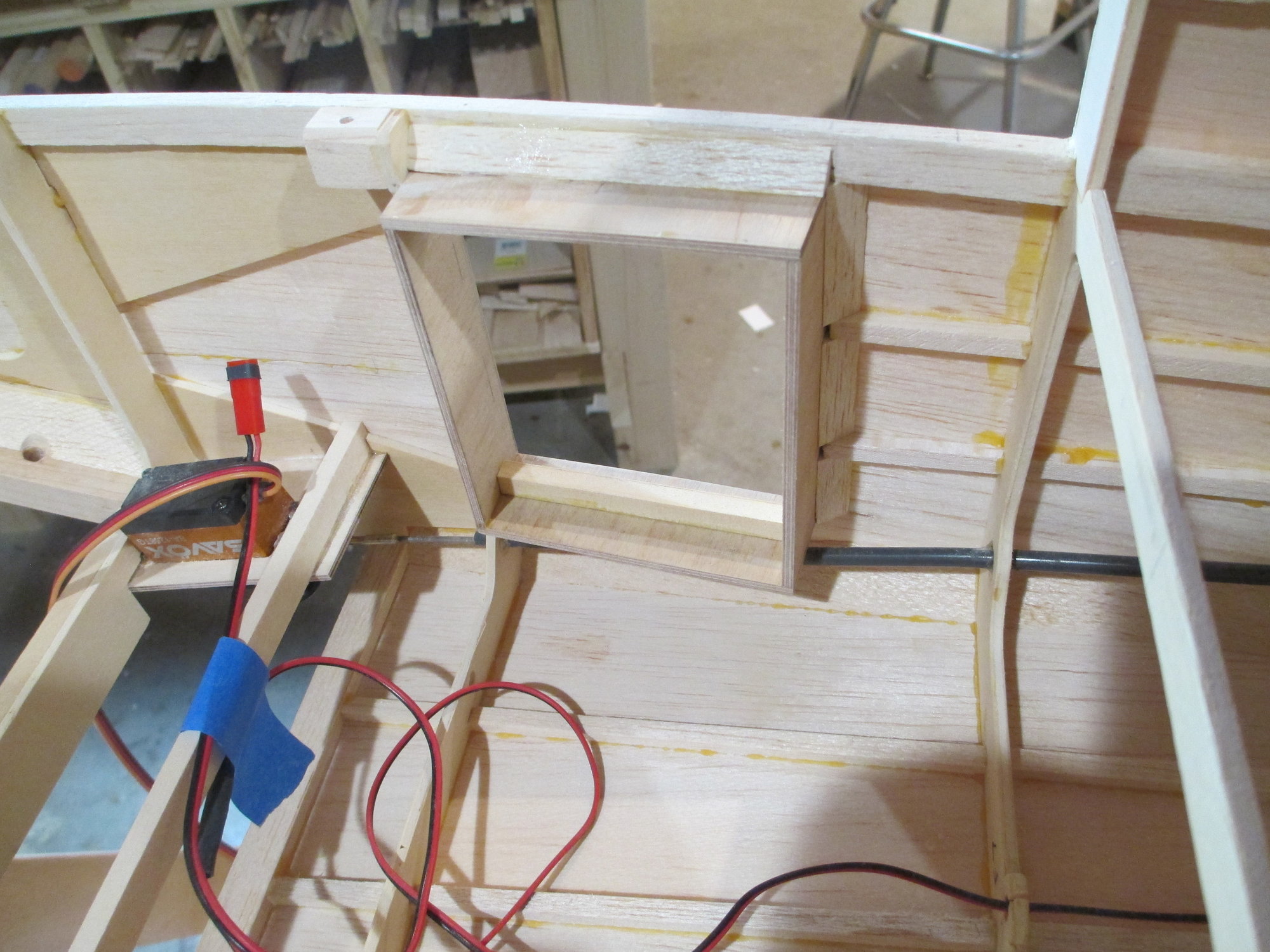
An opening was made in the right hand side of the fuselage which will serve as the rear baggage door that Bob's full scale Bonanza had. This scale feature will be used to hide all of the electronic switches and charging jacks that would normally be found on the outside of the model.
Removing the stringers and sheeting from the side of the fuselage creates a weak point. A 3/16" thick birch plywood box will add back structure and make it stronger than before I made the opening.
Last edited by VincentJ; 01-01-2020 at 01:11 PM.
 01-02-2020, 06:27 AM
#633
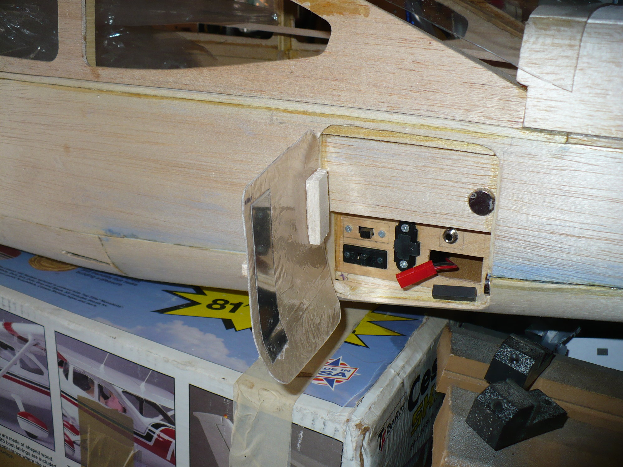
The phono jack is the remote glow plug connection. Makes it easier to start that way and I can keep my digits away from the spinning blade! When I was a kid I learned respect for spinning props the hard way. I got bit a number of times by an .049 and a .020 and still have a scar or two to prove it.. I don't even want to imagine what a .75 would do.
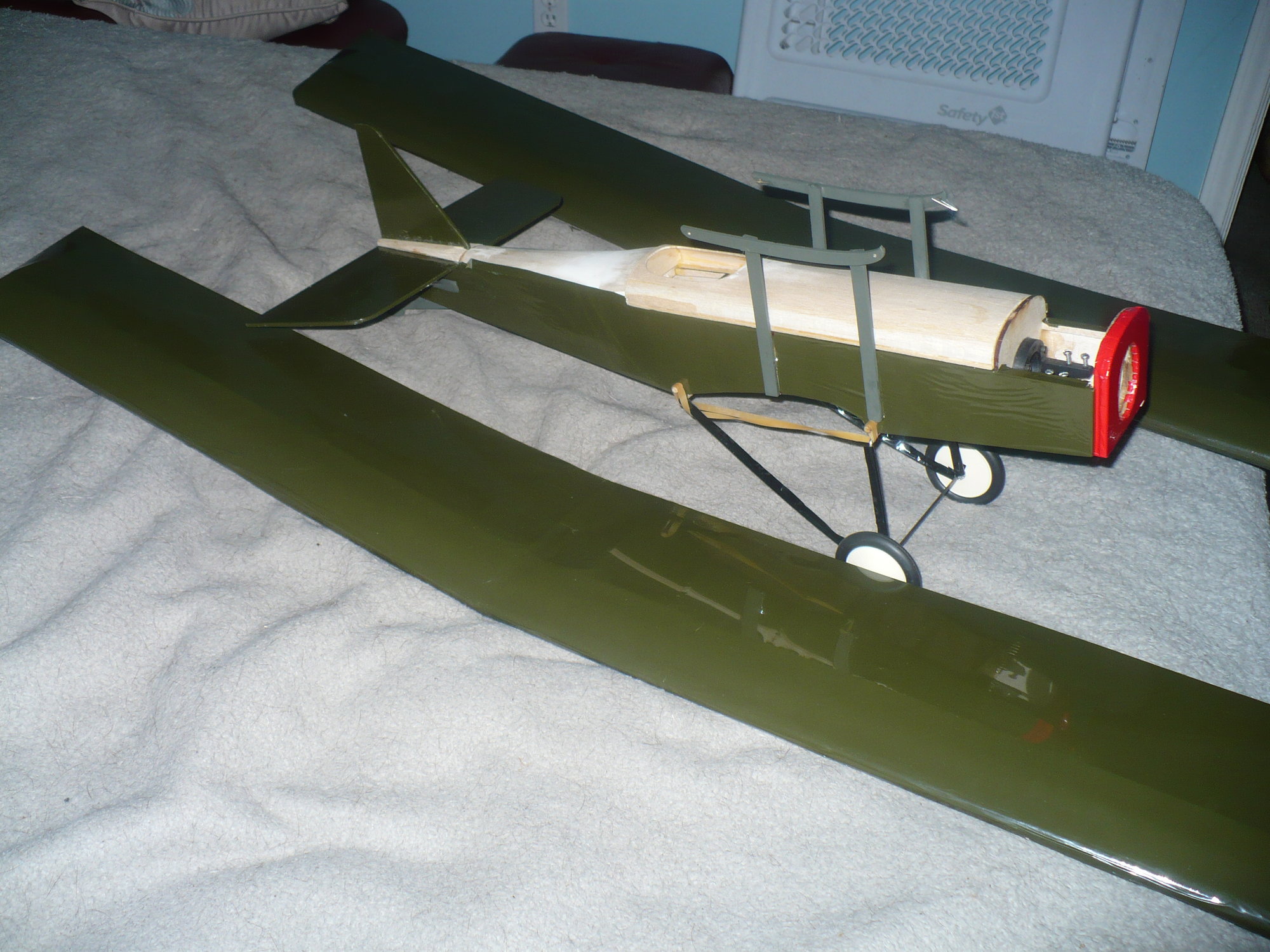
I got a little build time in yesterday. Here is my Ken Willard Sunday Fighter I am building for the grandkids. I got the Cabane struts, tail surfaces, and tail skid mounted, landing gear bent, and the pushrods installed. Next its smooth out the vertical fin supports to the rear turtleback,finish the covering and get the wrinkles out, install tank, engine, and throttle cable. Apply the roundlets and the pilot and she will be ready to fly. Power is a NIB OS .10 FP.
I got a little build time in yesterday. Here is my Ken Willard Sunday Fighter I am building for the grandkids. I got the Cabane struts, tail surfaces, and tail skid mounted, landing gear bent, and the pushrods installed. Next its smooth out the vertical fin supports to the rear turtleback,finish the covering and get the wrinkles out, install tank, engine, and throttle cable. Apply the roundlets and the pilot and she will be ready to fly. Power is a NIB OS .10 FP.
01-02-2020, 03:11 PM
#635
Thread Starter
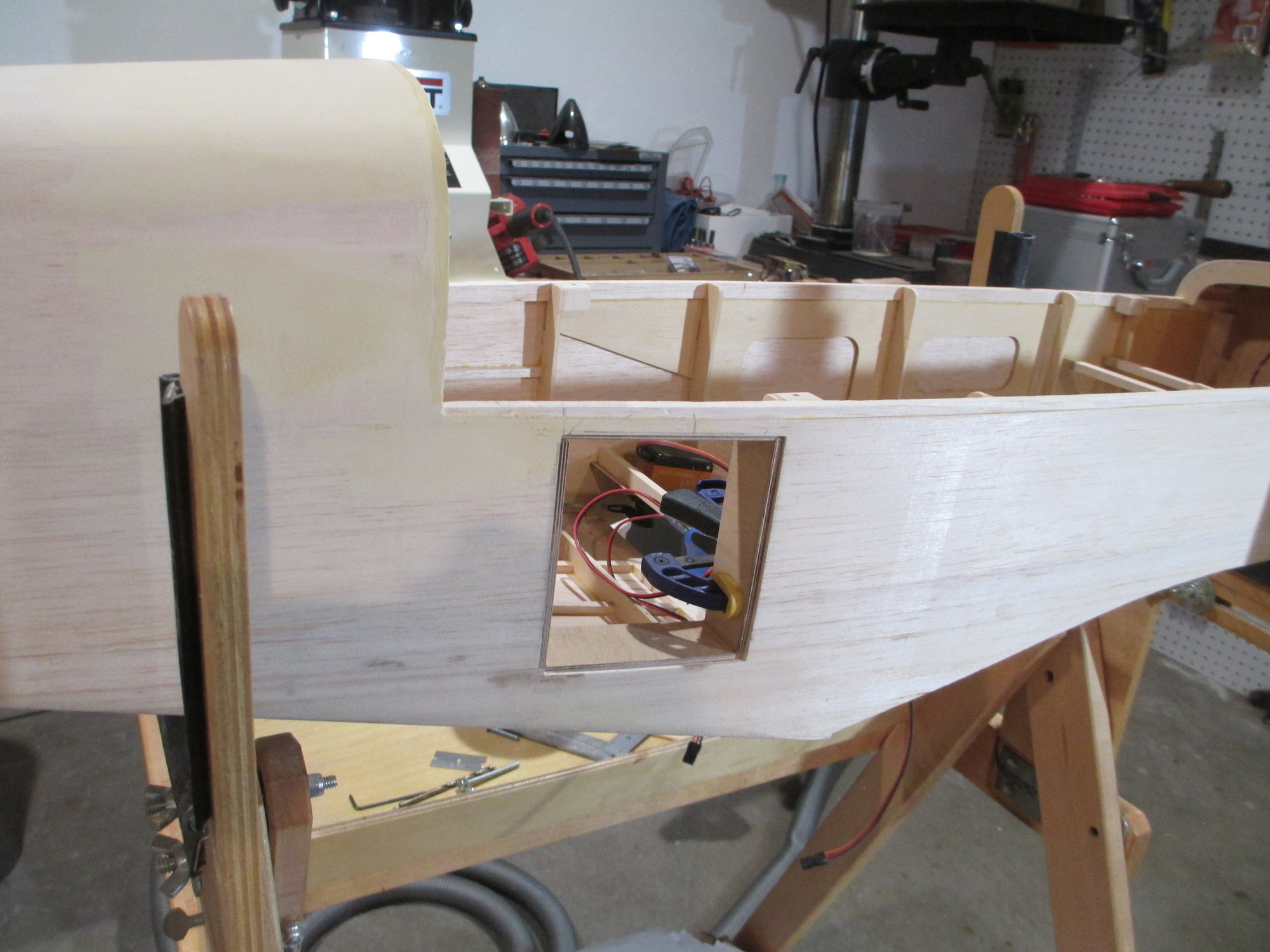
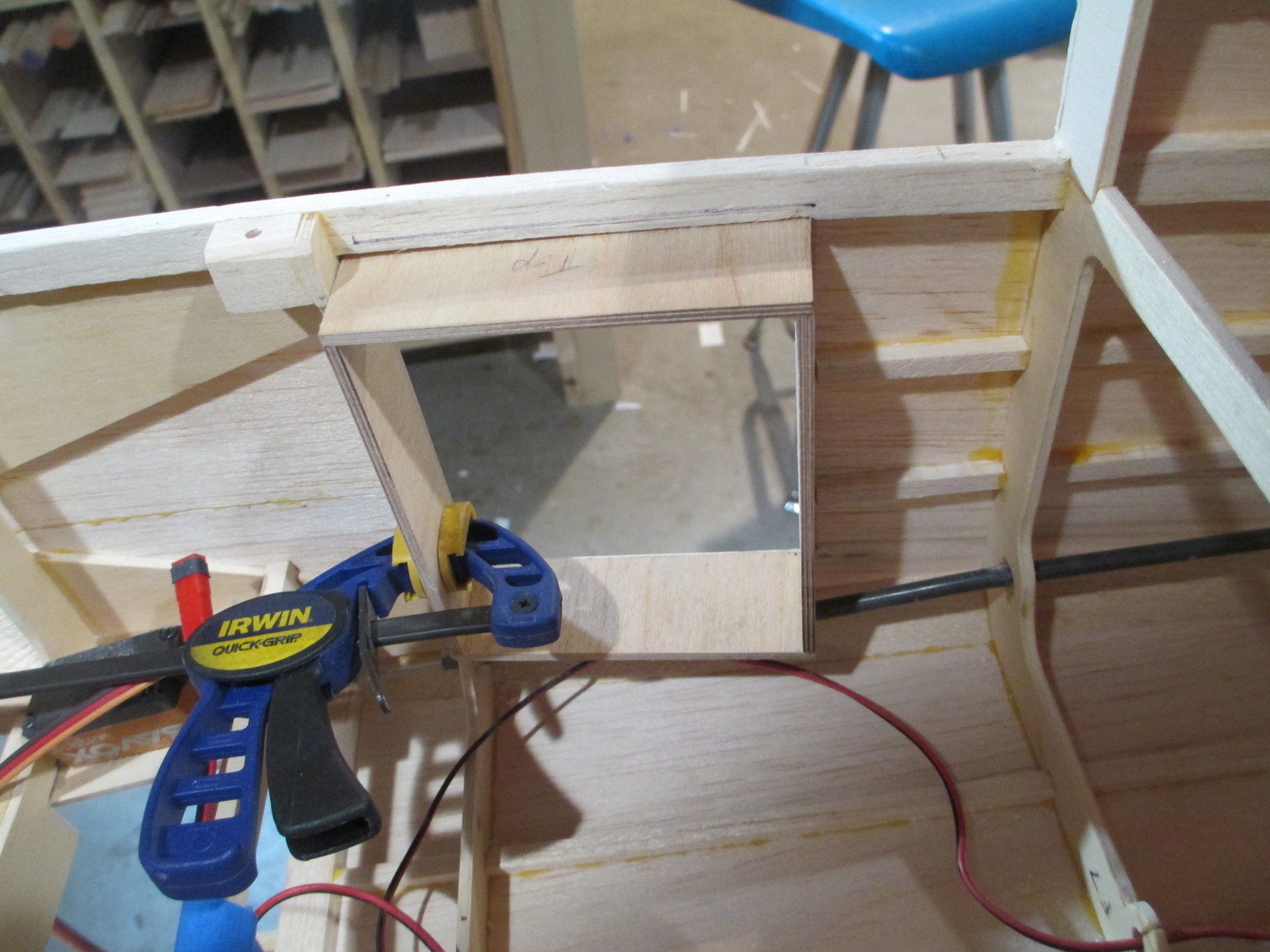
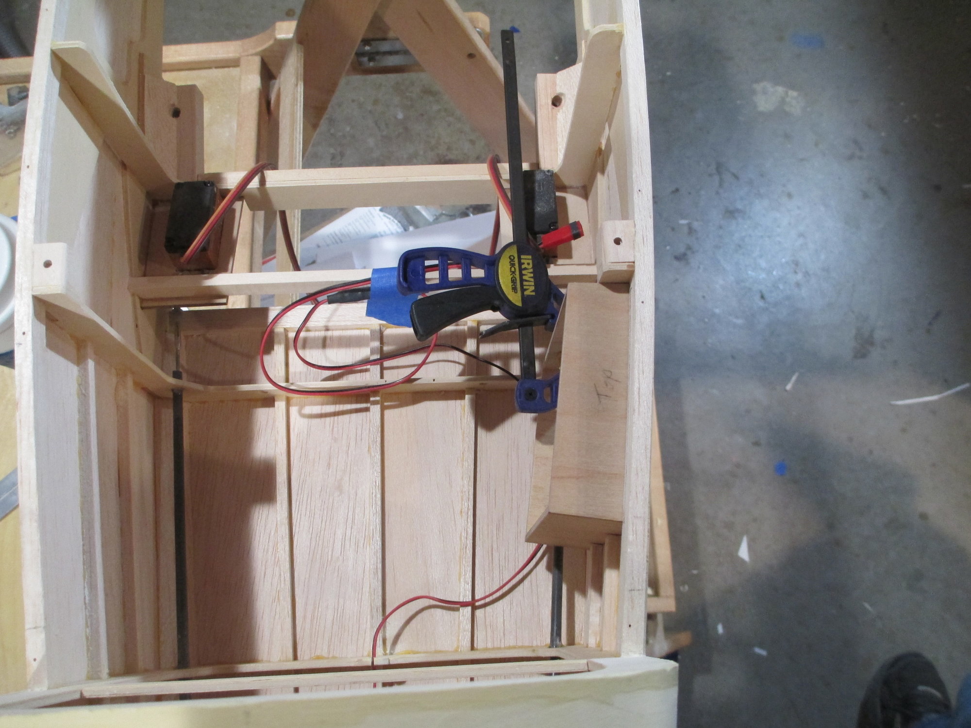
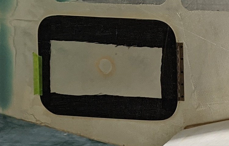
The baggage box has been reinforced with 1/4" balsa tri-stock. The addition of this cutout didn't weaken the structure in the least, in fact, it's much stronger now!
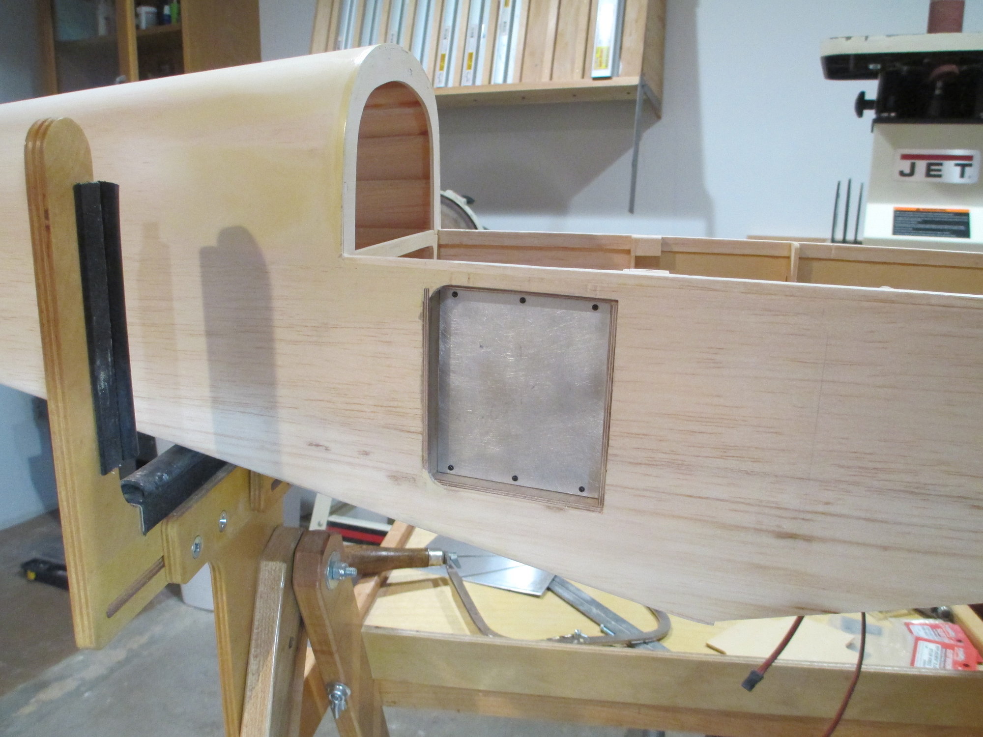
.032" aluminum sheet stock was cut to fit. I will cut out for the Jacks and switches later when I know how many I will need. The aluminum sheet is removable.
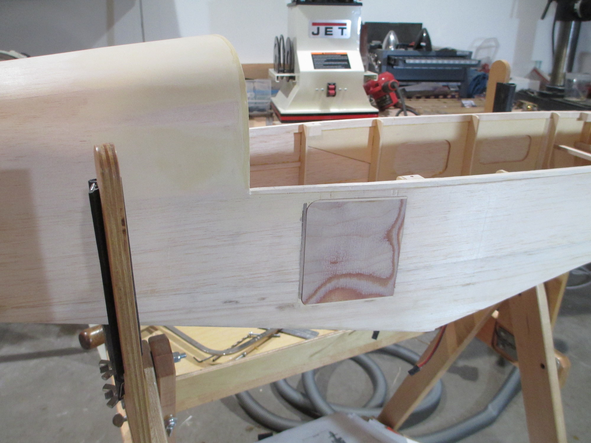
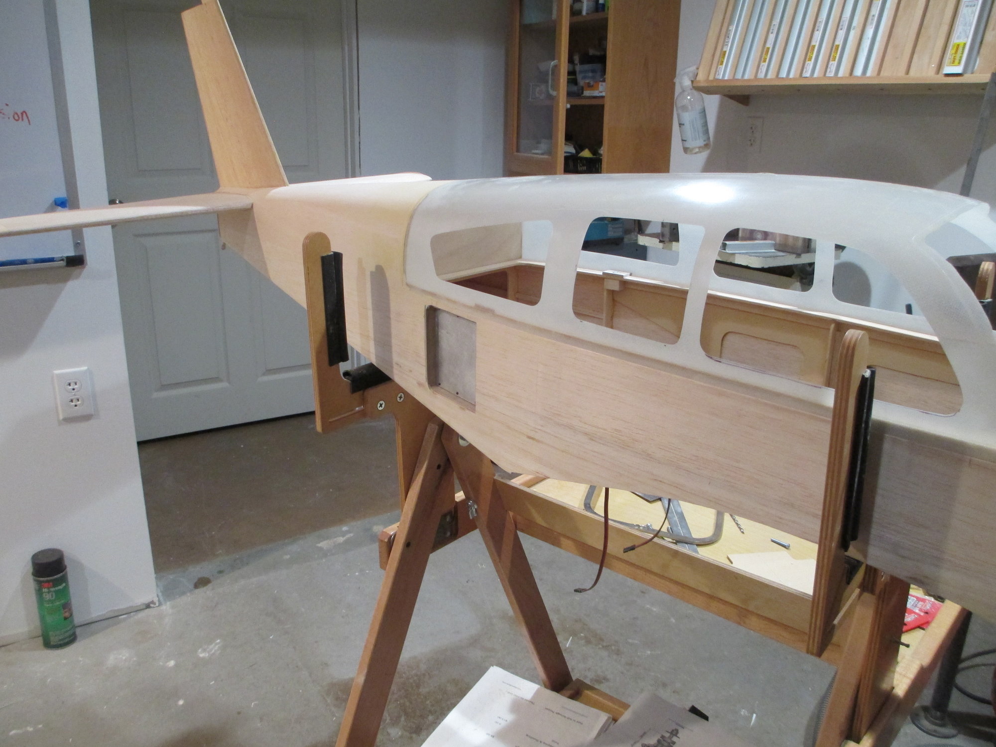
The cover was fabricated and trimmed to fit. The cover is made-up from three pieces of wood that have been laminated together using epoxy. The inner and outer pieces are 1/32" birch plywood with a 1/16" balsa center. The lamination follows the shape of the fuselage as it is not flat. It fits extremely well. I'm still undecided whether to use magnets to hold the cover in place or to use two hinges along with a magnet to keep the cover closed.
 01-02-2020, 04:34 PM
#636

My question is how is the door mounted on the full size aircraft? I know one commonly used piece of hardware is a piano hinge. If that's what is used on the full sized plane, you might consider a magnet and this:
https://www.micromark.com/Miniature-...60-in-x-15-in-
https://www.micromark.com/Miniature-...60-in-x-15-in-
01-02-2020, 04:53 PM
#637
Thread Starter
My question is how is the door mounted on the full size aircraft? I know one commonly used piece of hardware is a piano hinge. If that's what is used on the full sized plane, you might consider a magnet and this:
https://www.micromark.com/Miniature-...60-in-x-15-in-
https://www.micromark.com/Miniature-...60-in-x-15-in-
Unless I just keep the size of the door that I made without adding to its length, then I could (and would) use a piano hinge. Hope this all makes sense!
Last edited by VincentJ; 01-02-2020 at 05:03 PM.
 01-04-2020, 11:54 AM
#640
Thread Starter
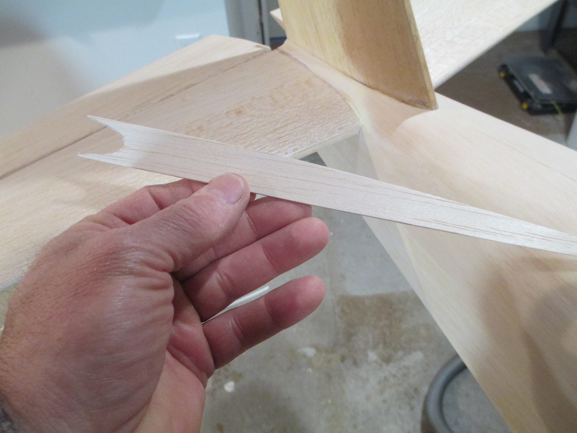
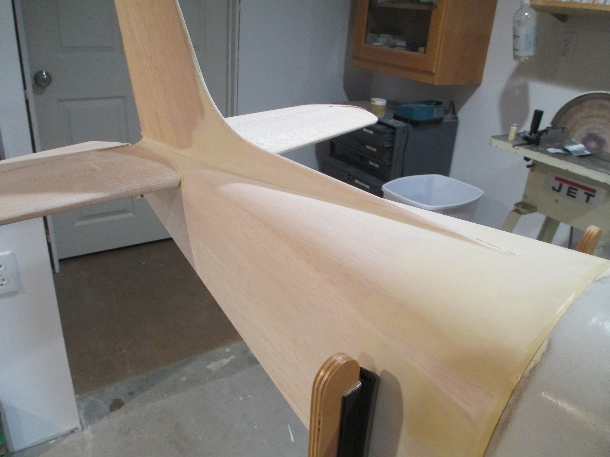
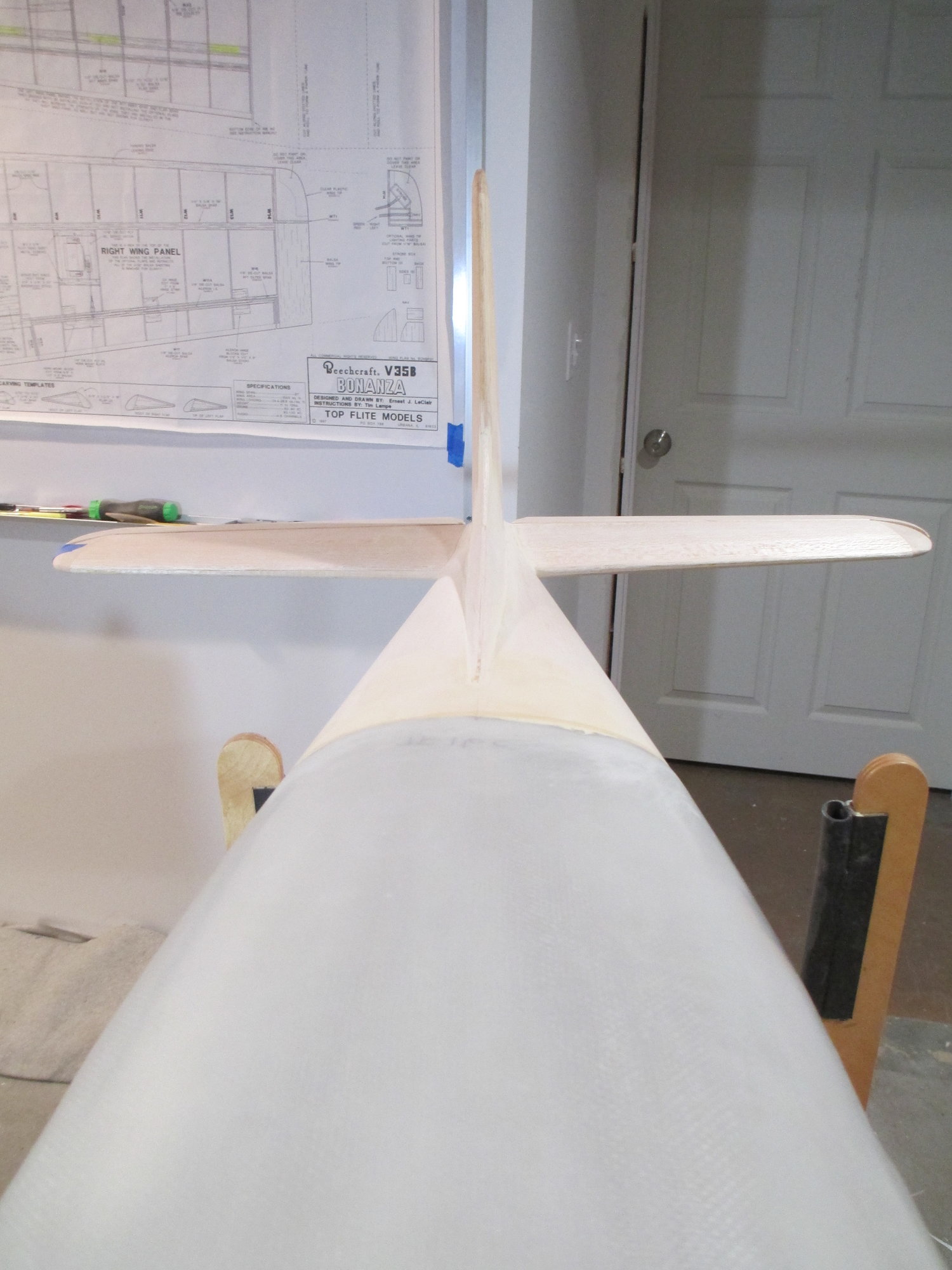
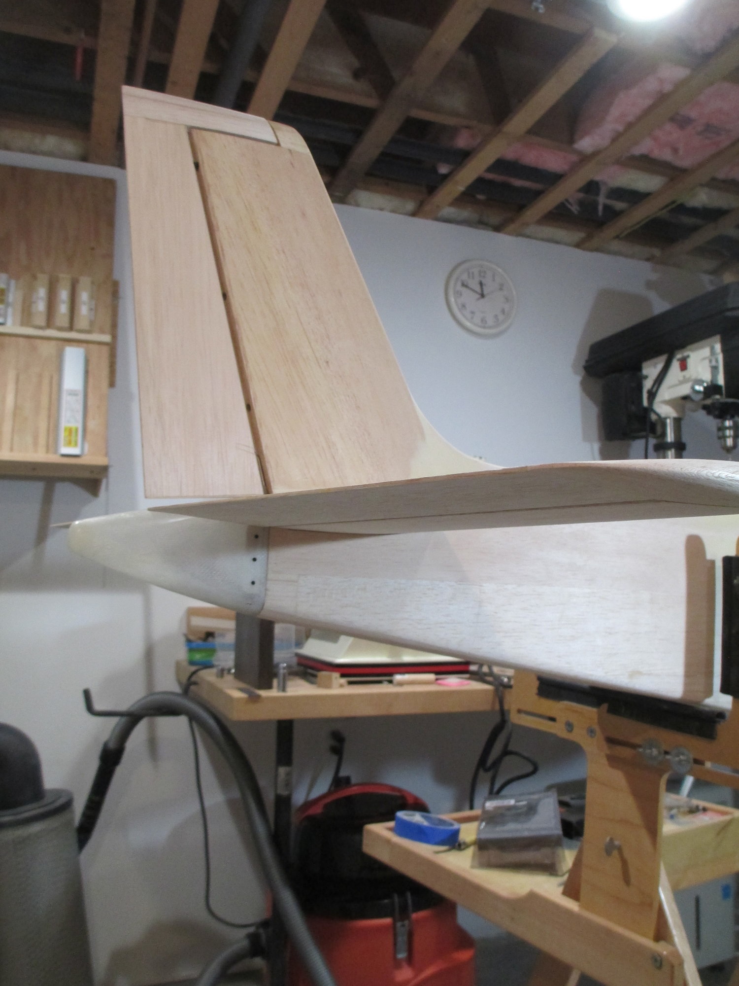
Time to build the dorsal fin. It all starts by cutting out 1/16" sheet balsa to create the dorsal fin base.
The base is fitted around the leading edge of the fin and glued in place making sure it is centered over the fuses center line.
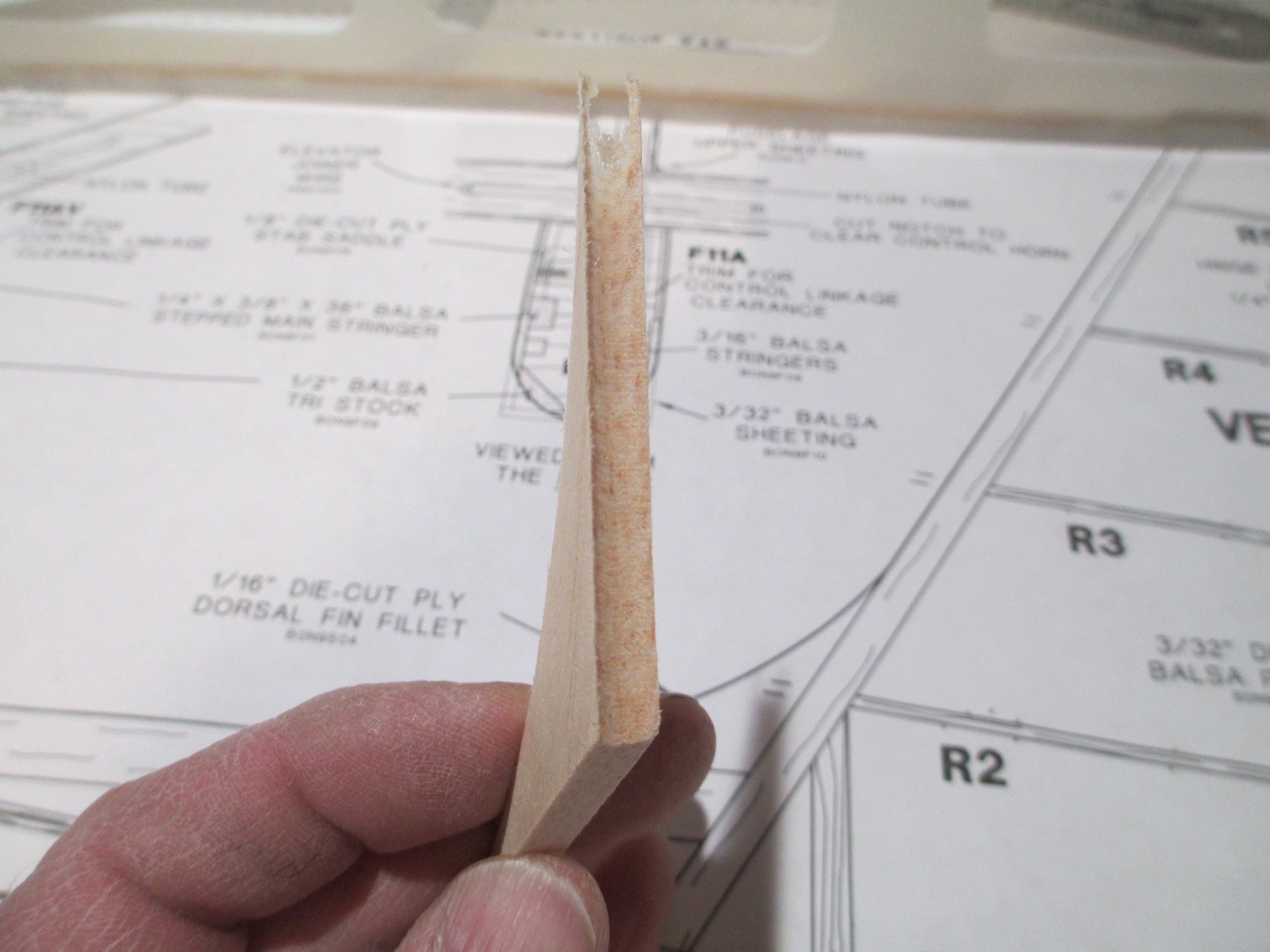
Tapered balsa stock is cut and glued forming the dorsal fin's leading edge.
01-04-2020, 01:40 PM
#641
Thread Starter
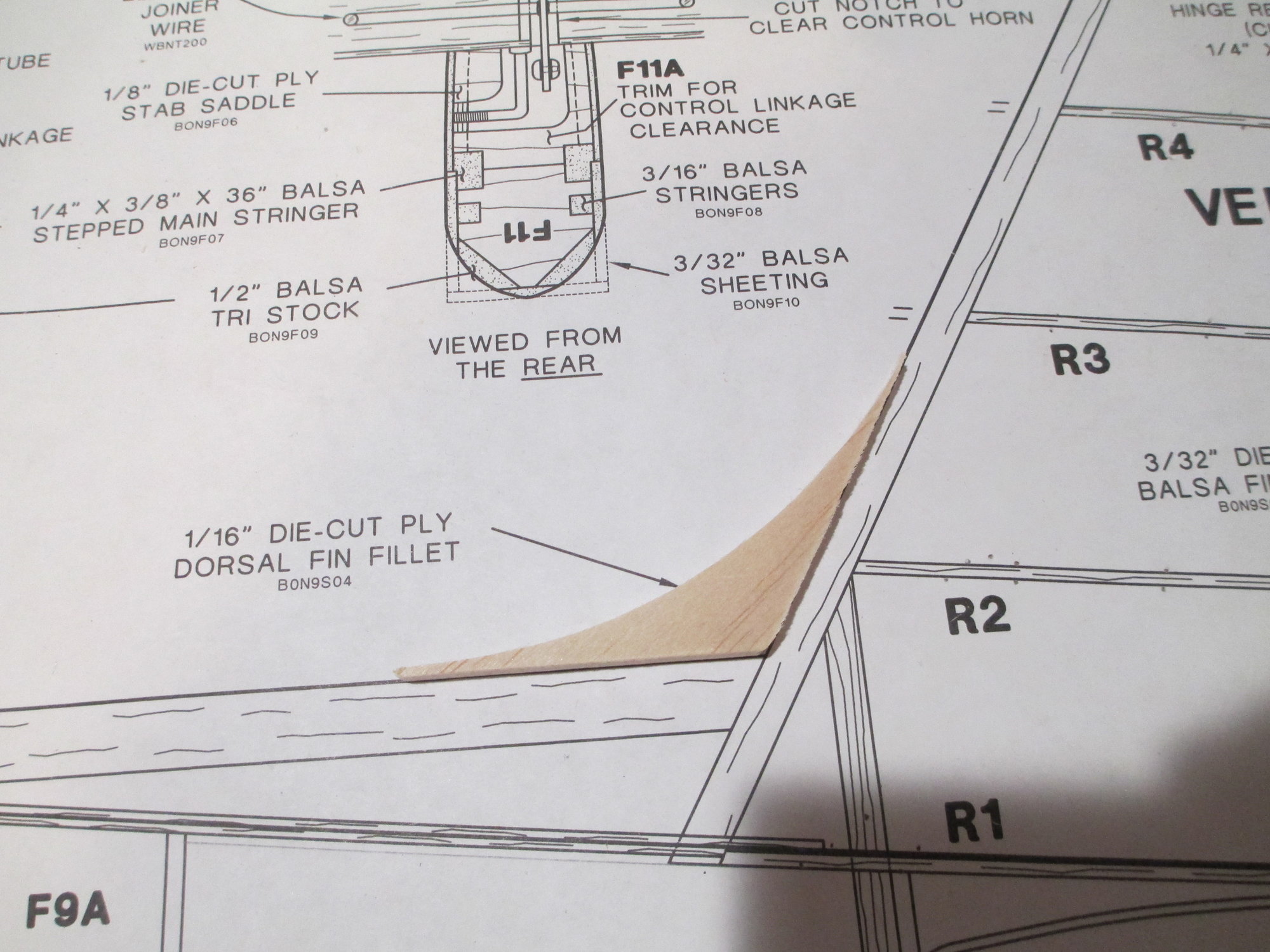
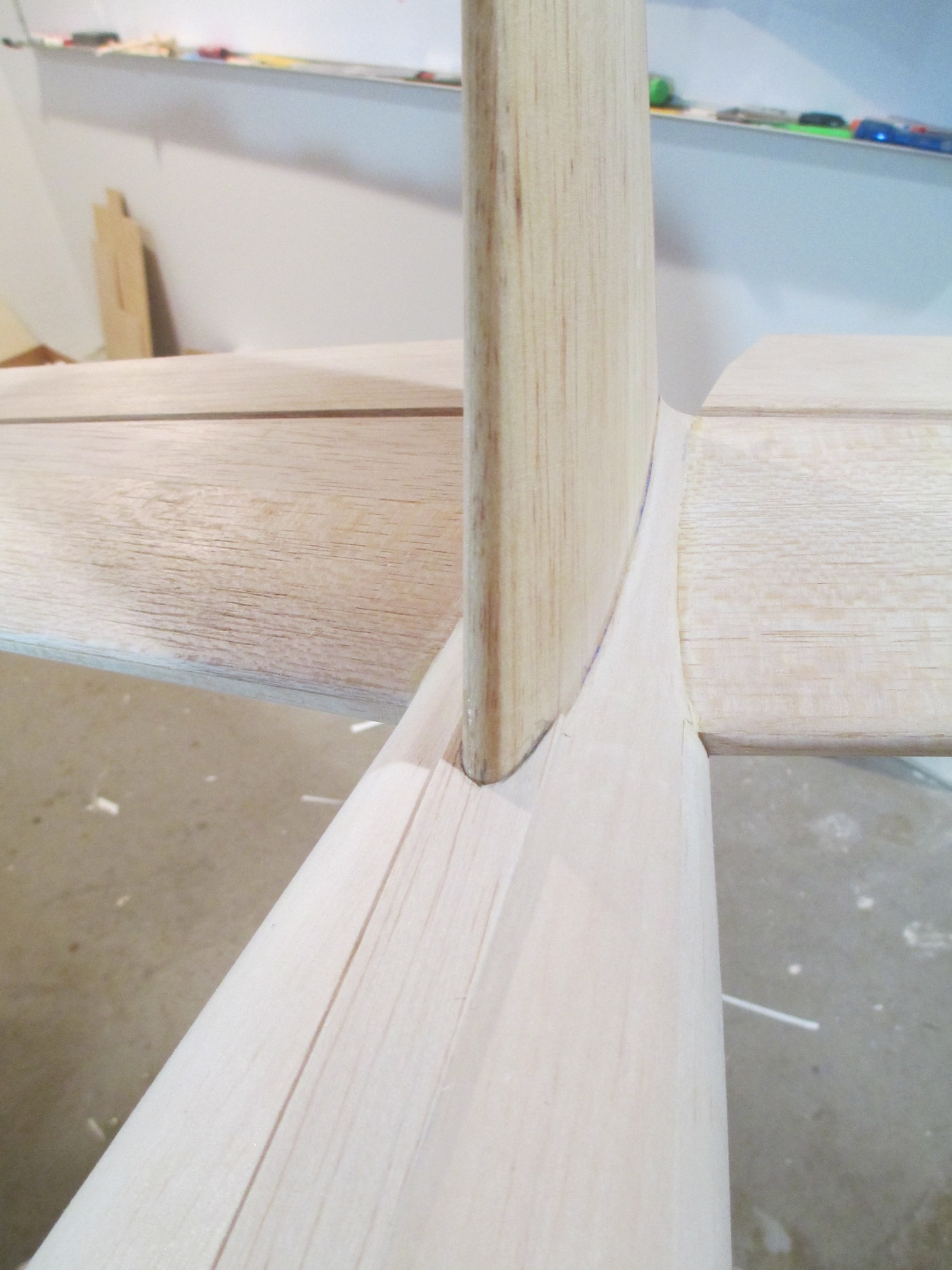
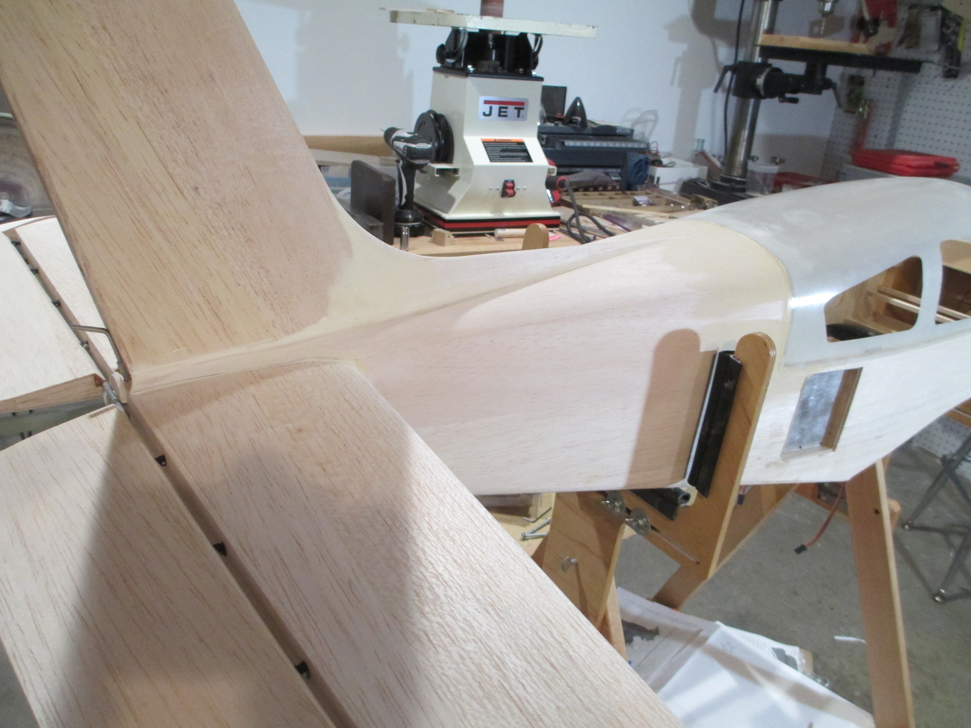
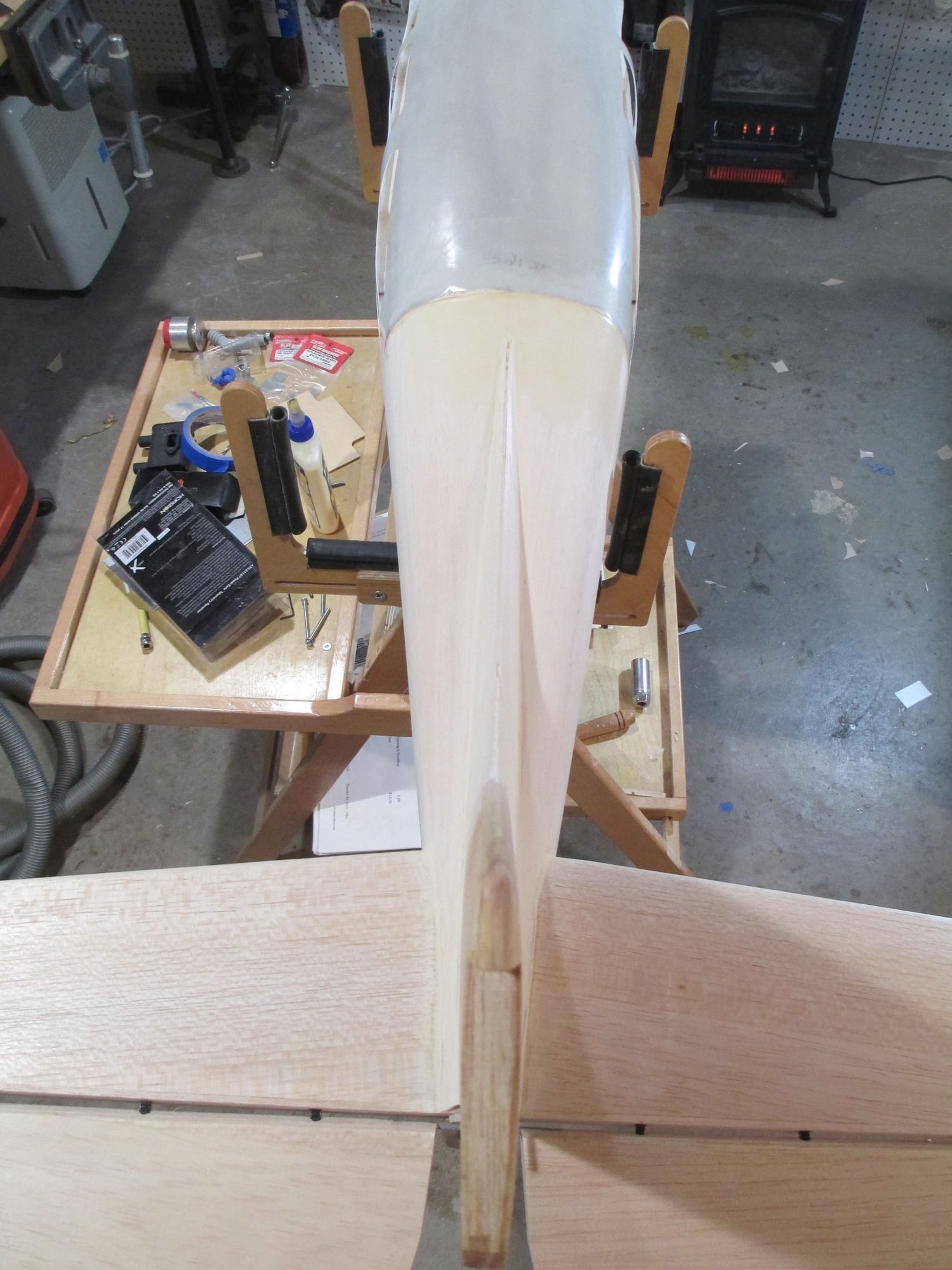
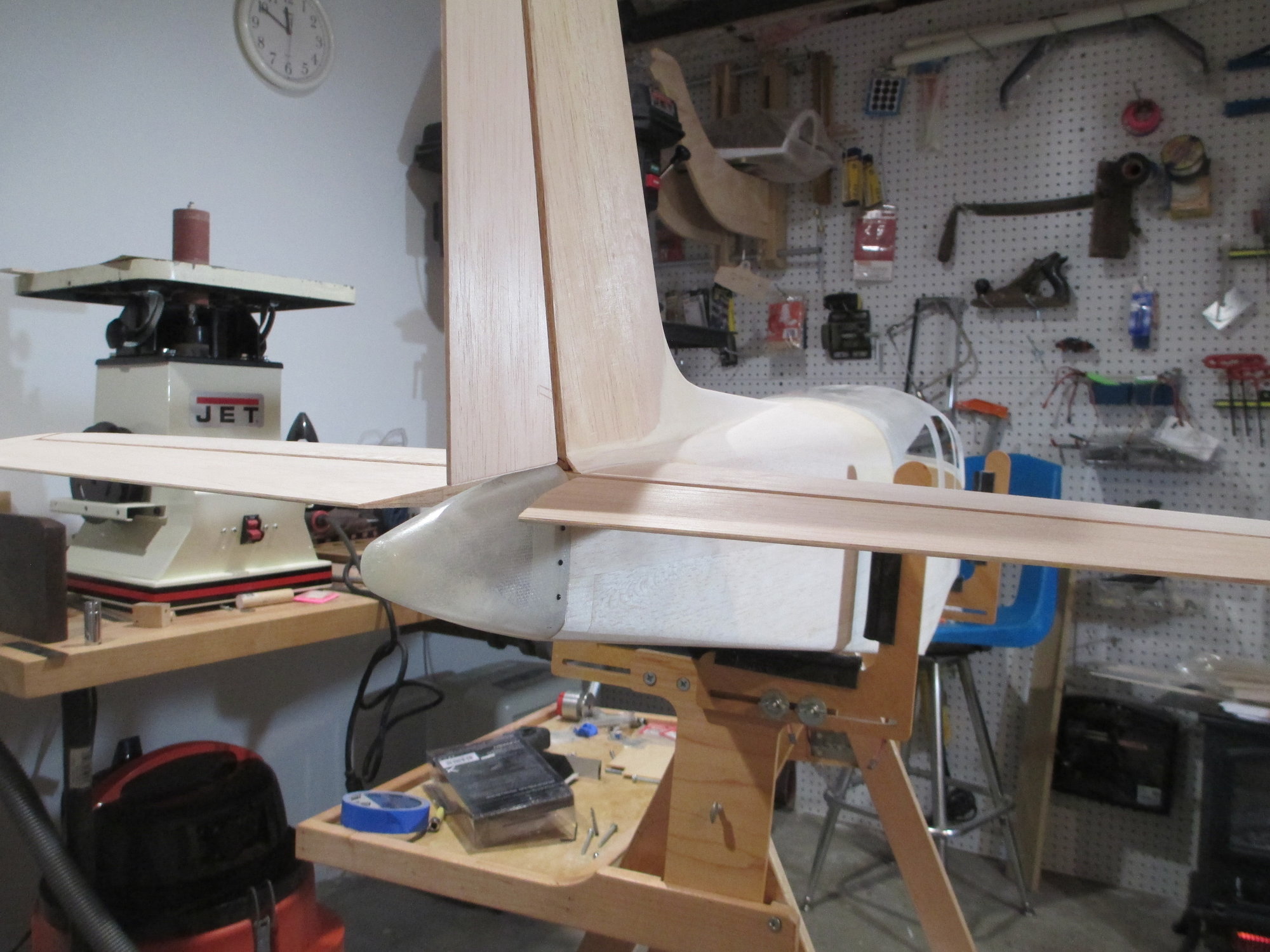
The plans specified a 1/16" ply dorsal fin fillet. I substituted it with 1/4" thick balsa. Too much filler would have had to be used if I used the thinner fillet. I understand filler is sometimes a necessary evil, but I do my best to limit its use.
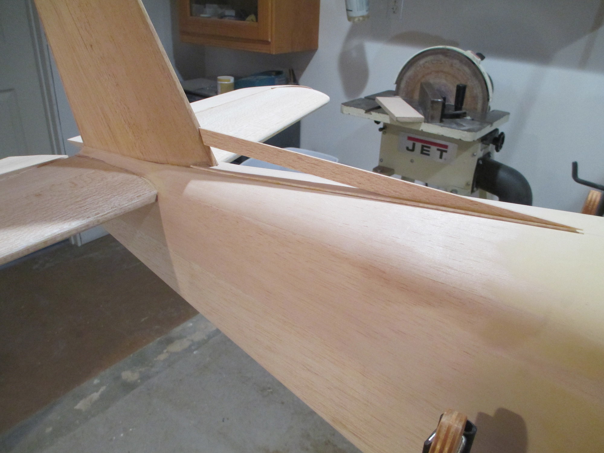
For a better fit, I matched the shape of the fin's leading edge to the vertical part of the fillet.
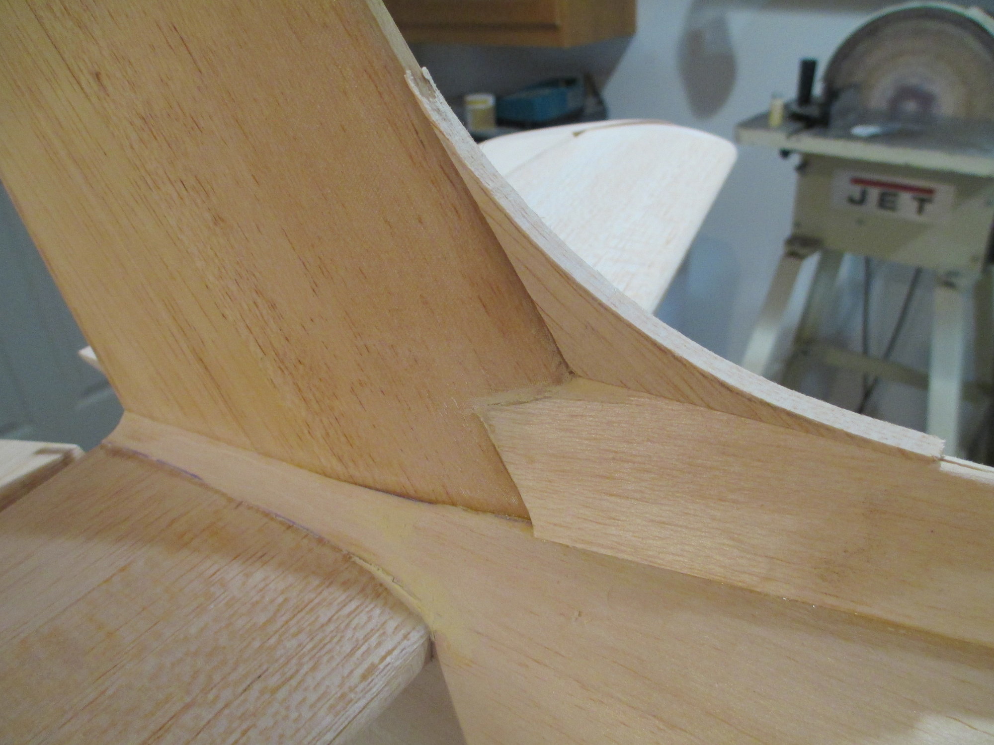
The sides of the dorsal fin have been sheeted using 1/16" balsa and fitted against the fin. I will use a small amount of filler to blend it all together once I'm done sanding/shaping.
Last edited by VincentJ; 01-04-2020 at 03:01 PM.
 01-05-2020, 09:22 AM
#646
Thread Starter
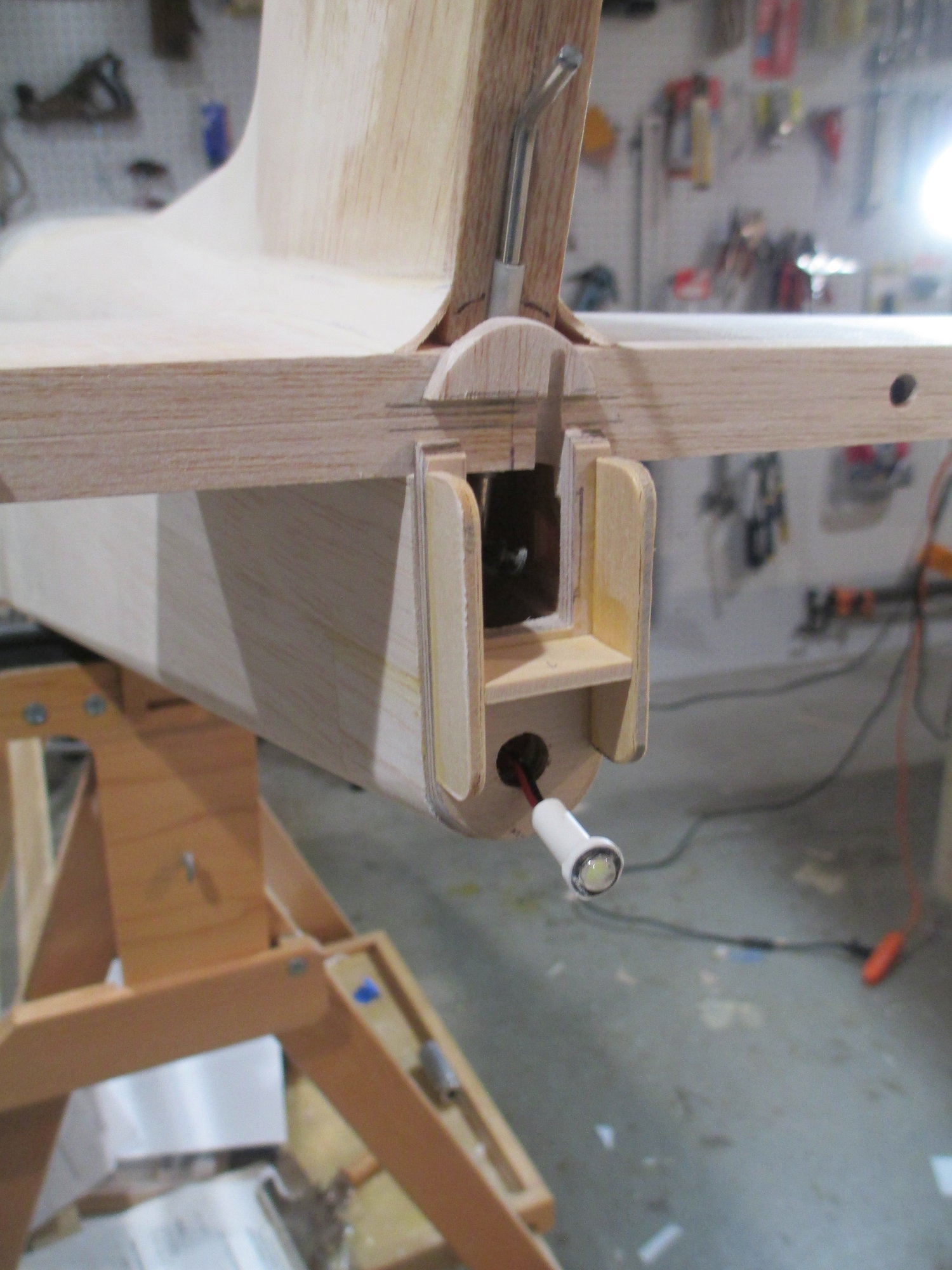
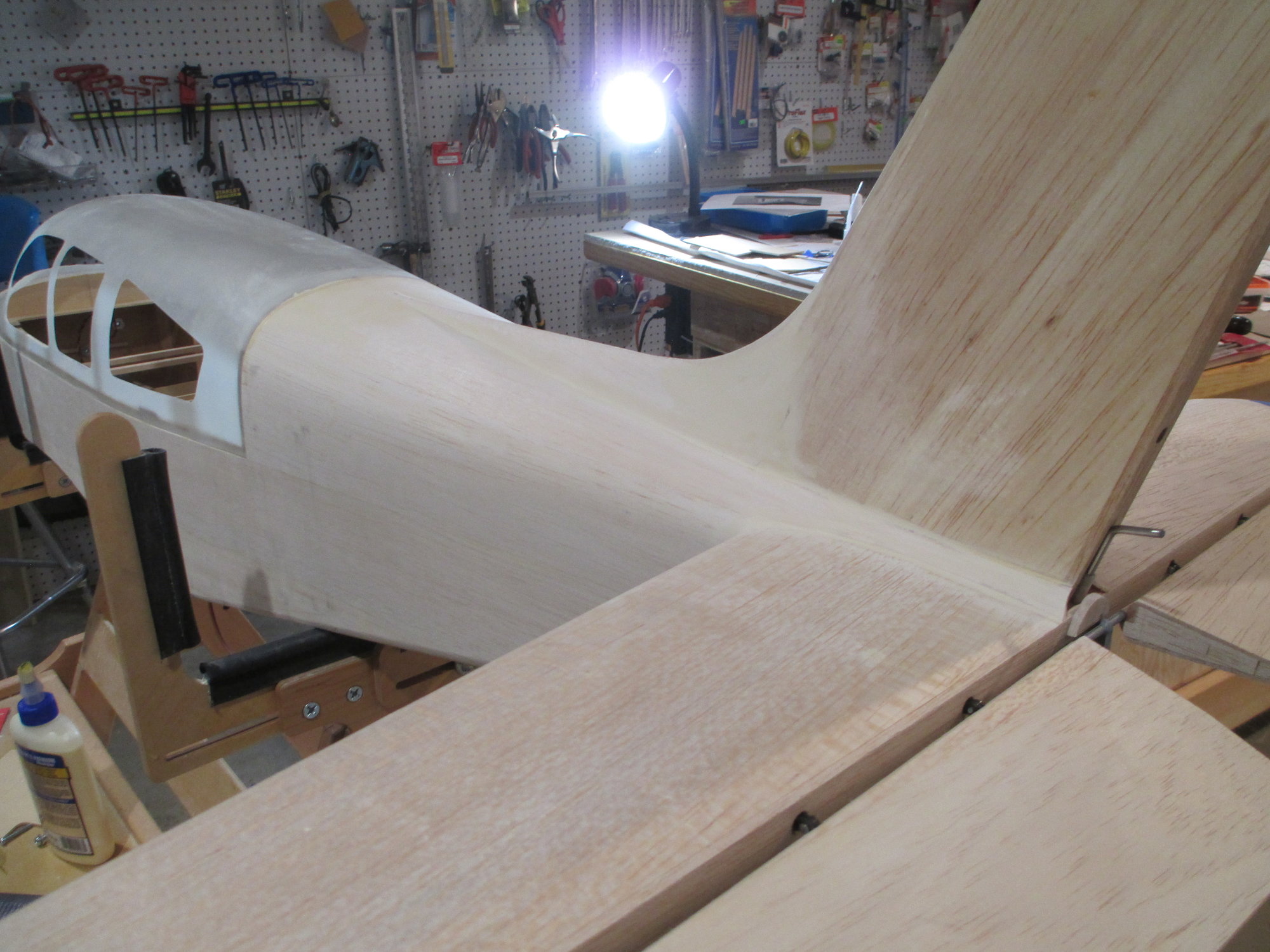
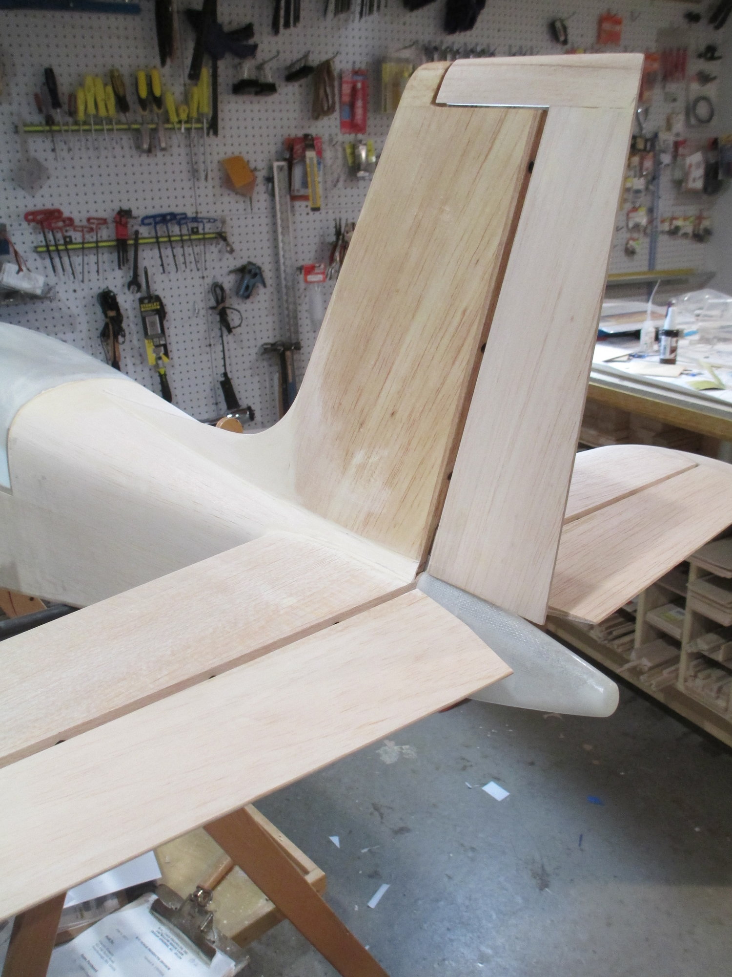
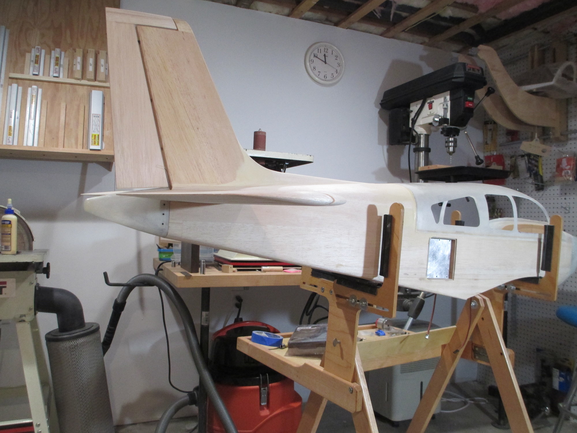
Time to install the tail cone. Two pieces of lite-plywood vertical mounts were glued on the aft section of the fuselage. This is where the tail cone will get screwed to.
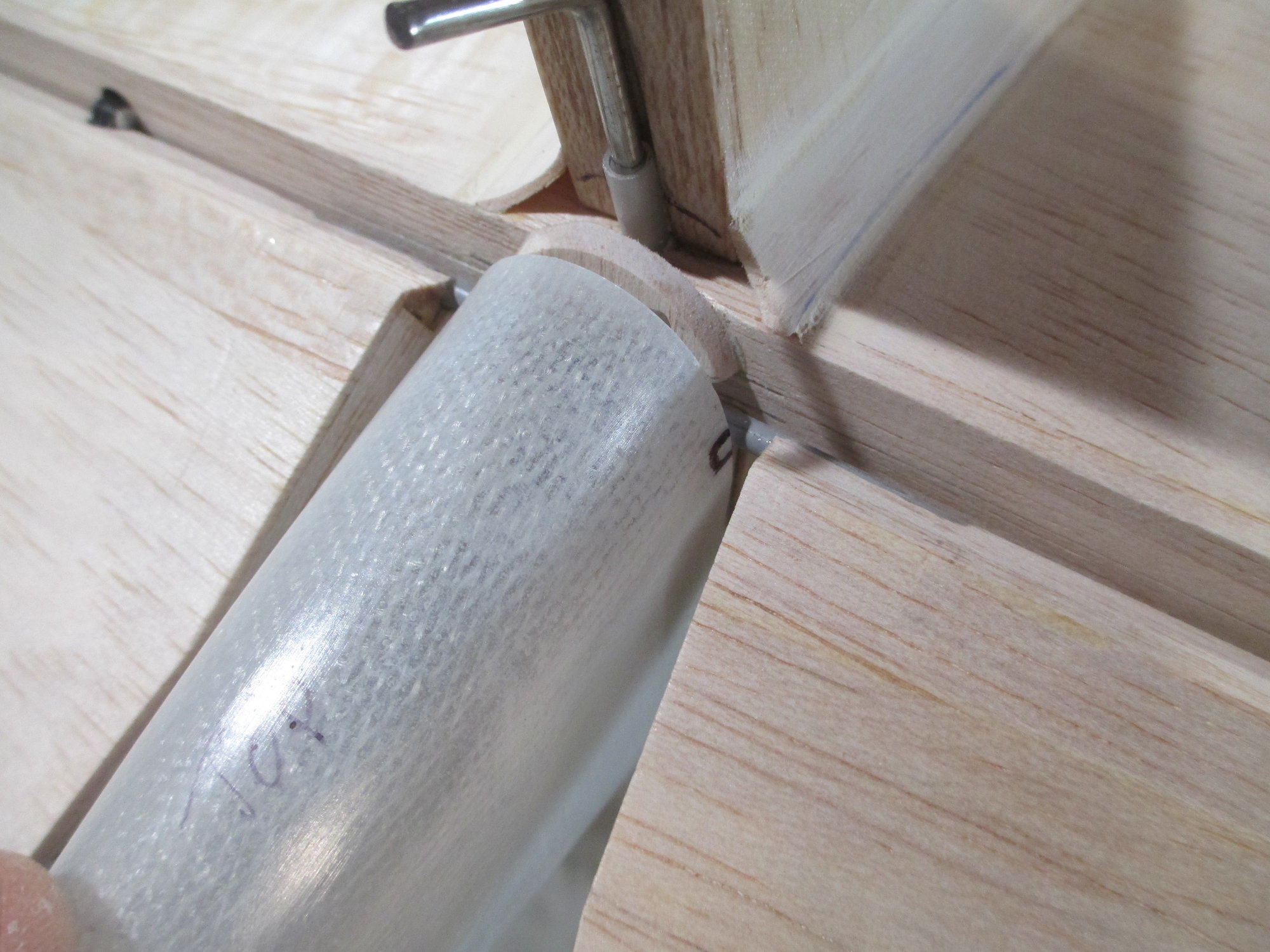
I knew that accommodations would need to be made to the tail cone because of the interference with the elevator joiner wire. The areas on the tail cone marked with a Sharpie with be filed.
Note: I marked "TOP" on the tail cone so as not to install it upside down which can easily be done.
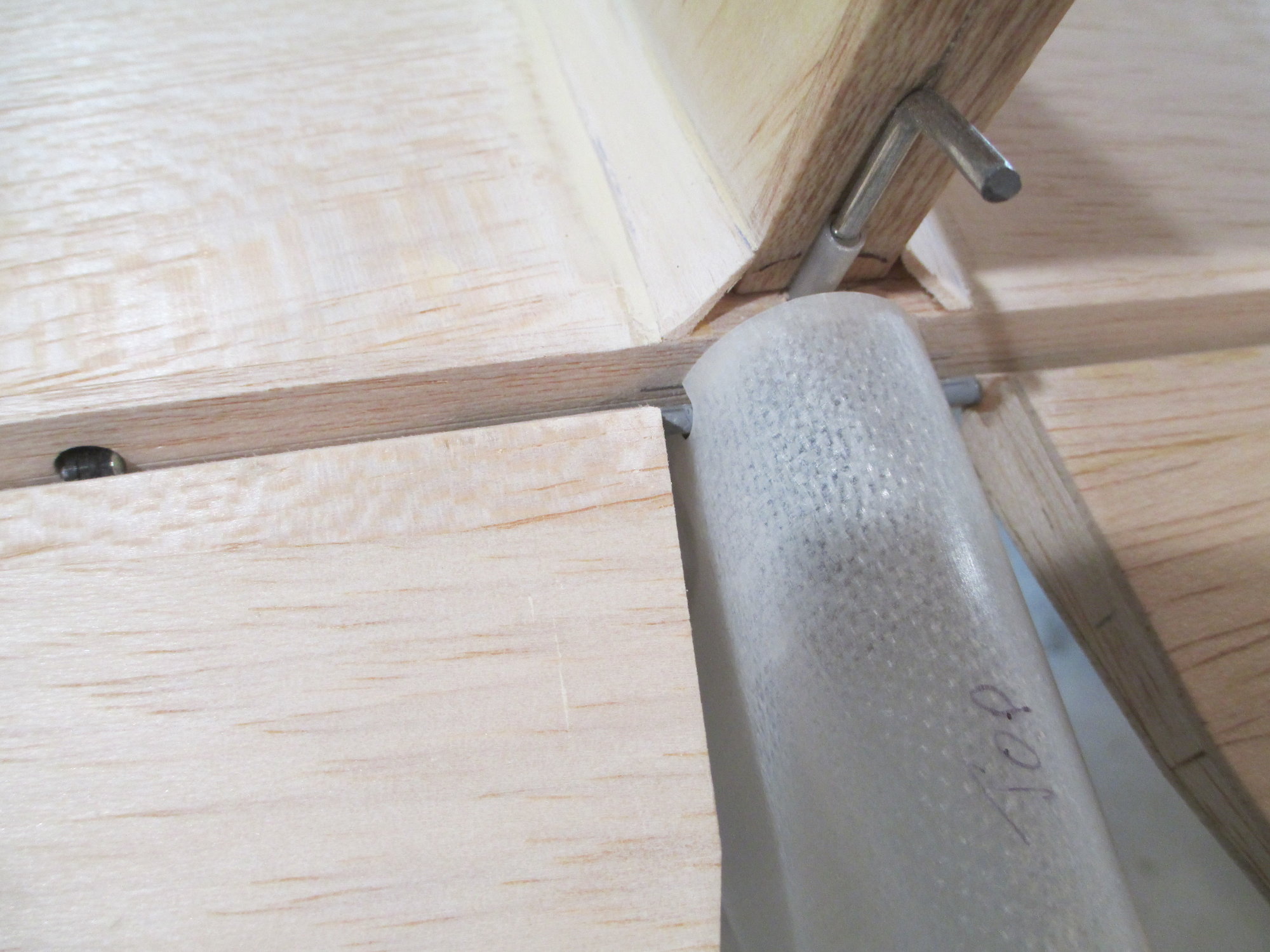
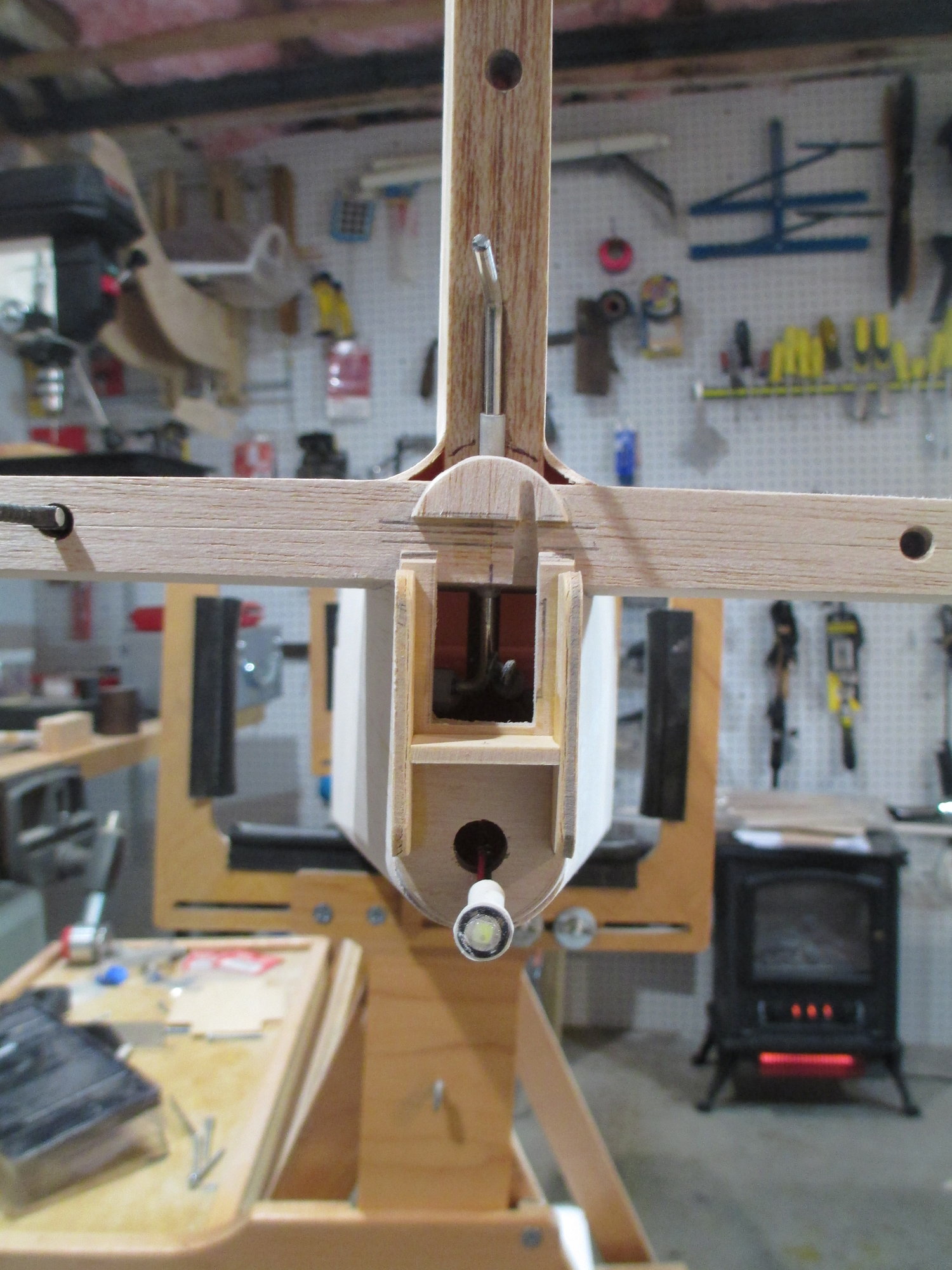
A few passes using a fine round hand file made quick work of removing the fiberglassed marked areas. Now the tail cone easily slips on without rubbing against the joiner wire.
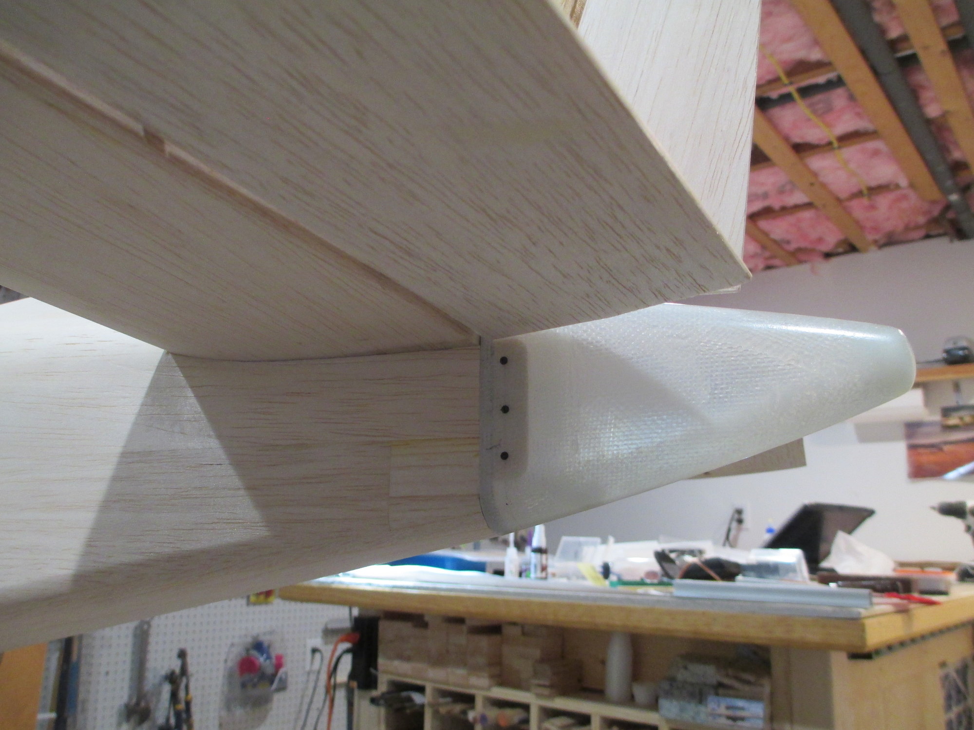
The tail cone is secured to the mounting brackets using six wood screws.
Last edited by VincentJ; 01-06-2020 at 03:48 AM.
01-05-2020, 12:01 PM
#648
Thread Starter