


TF Beechcraft Bonanza F33A Build
 10-25-2019, 04:45 AM
#376

I was thinking, we have a local upholstery supply house that sells retail and to upholstery shops. He stocks light weight fiberglass cloth by the roll and sells it by the square yard.. You might check a similar store in your area or ask someone who does fiberglass repair where they buy their cloth.
Mike
Mike
 10-26-2019, 05:59 AM
#382

Thread Starter
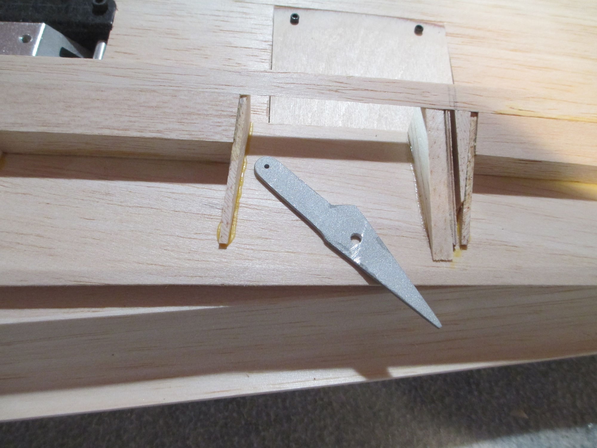
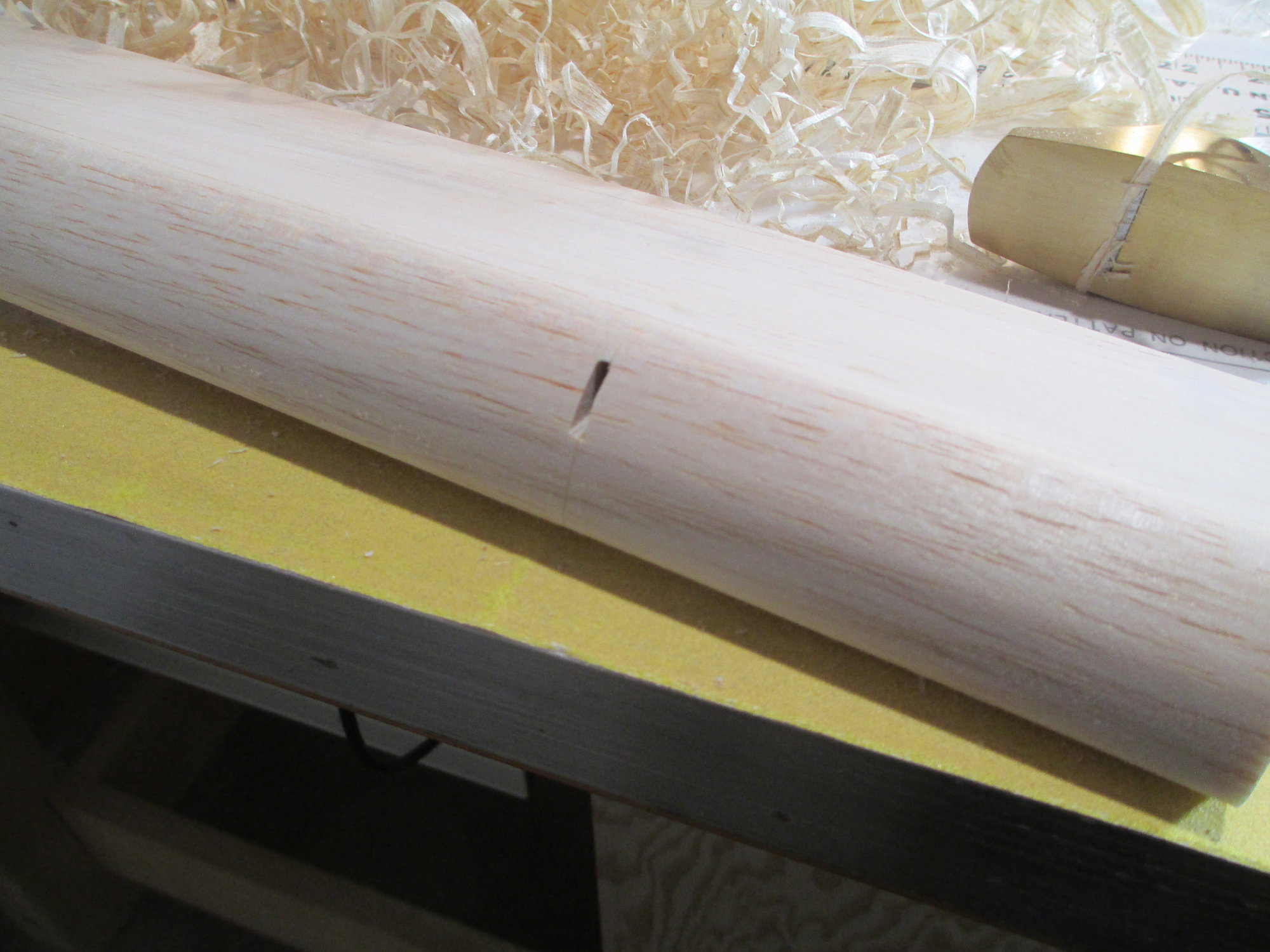
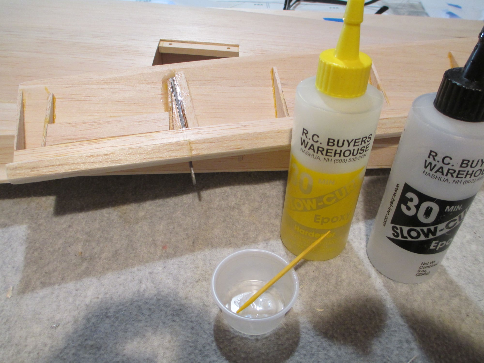
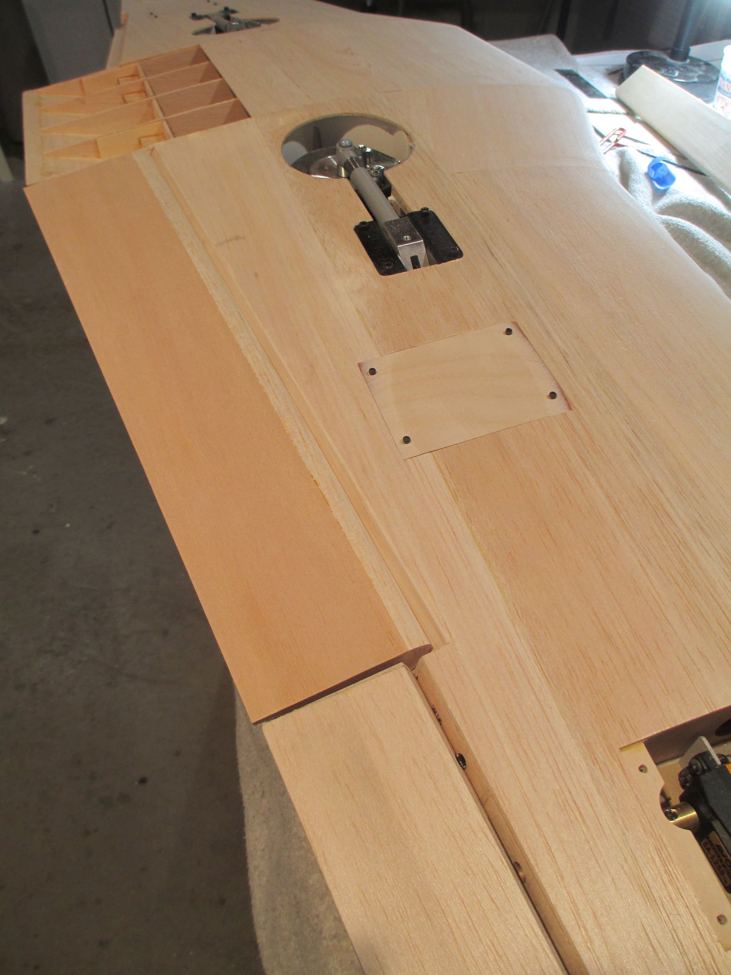
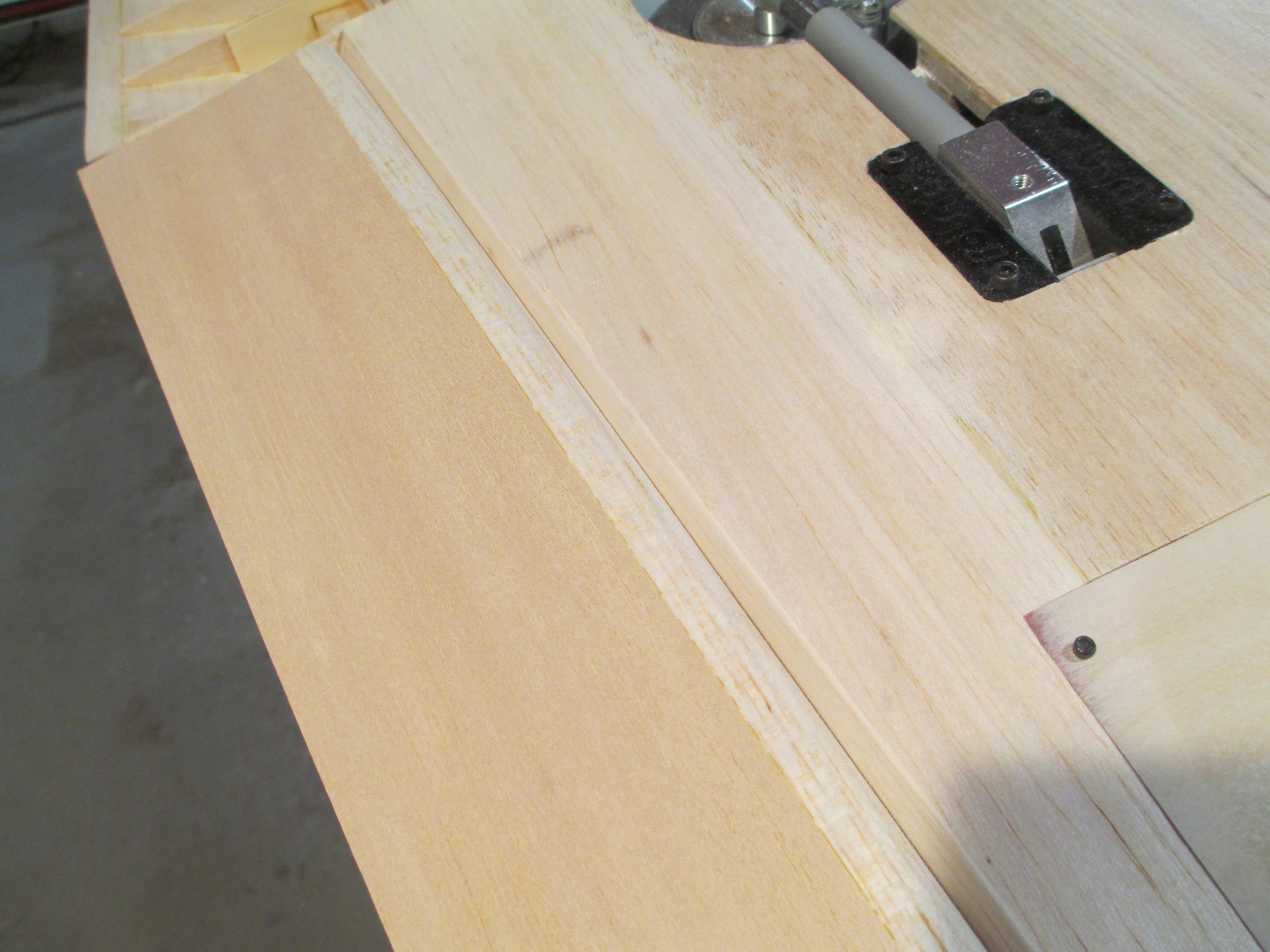
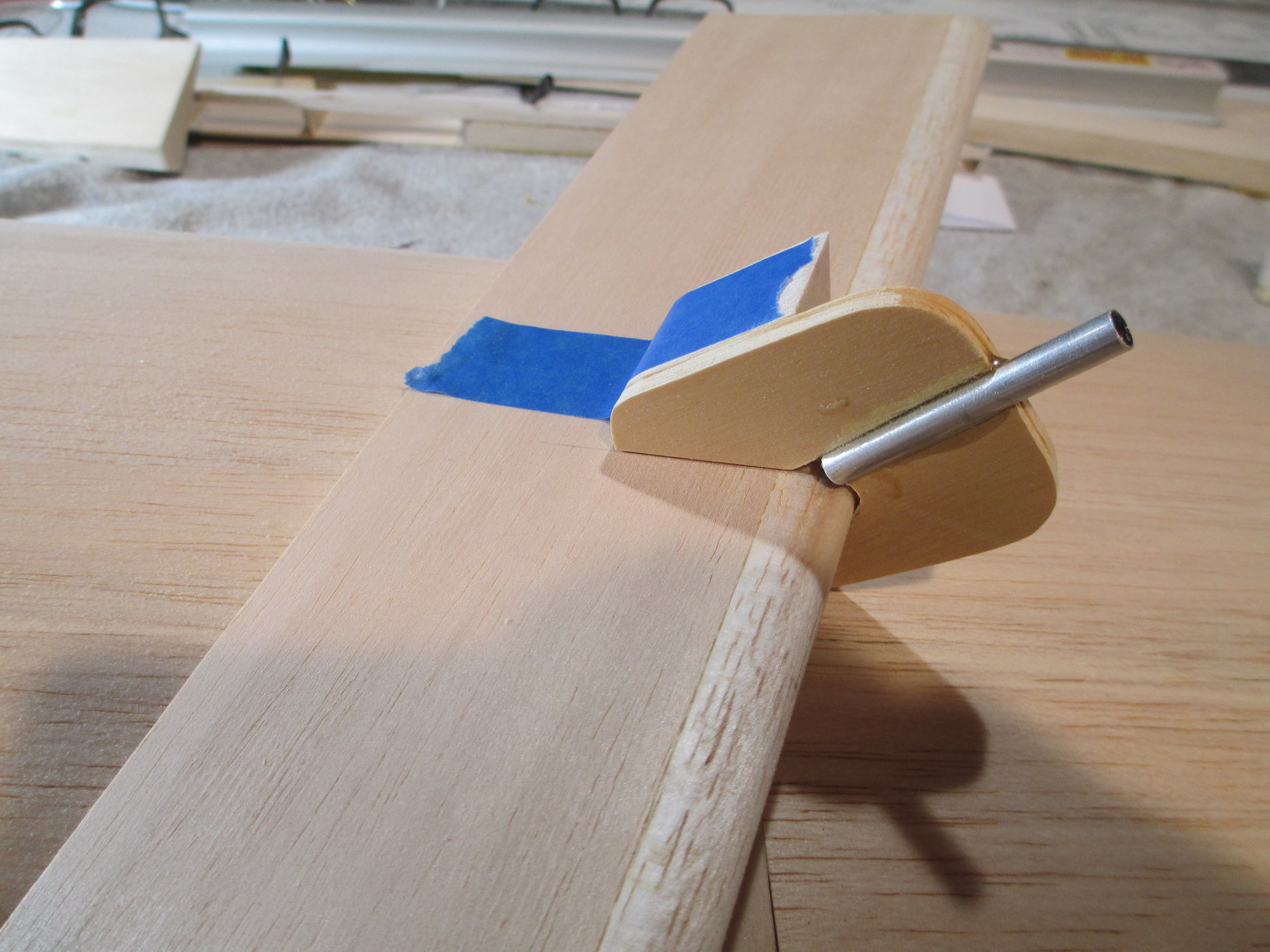
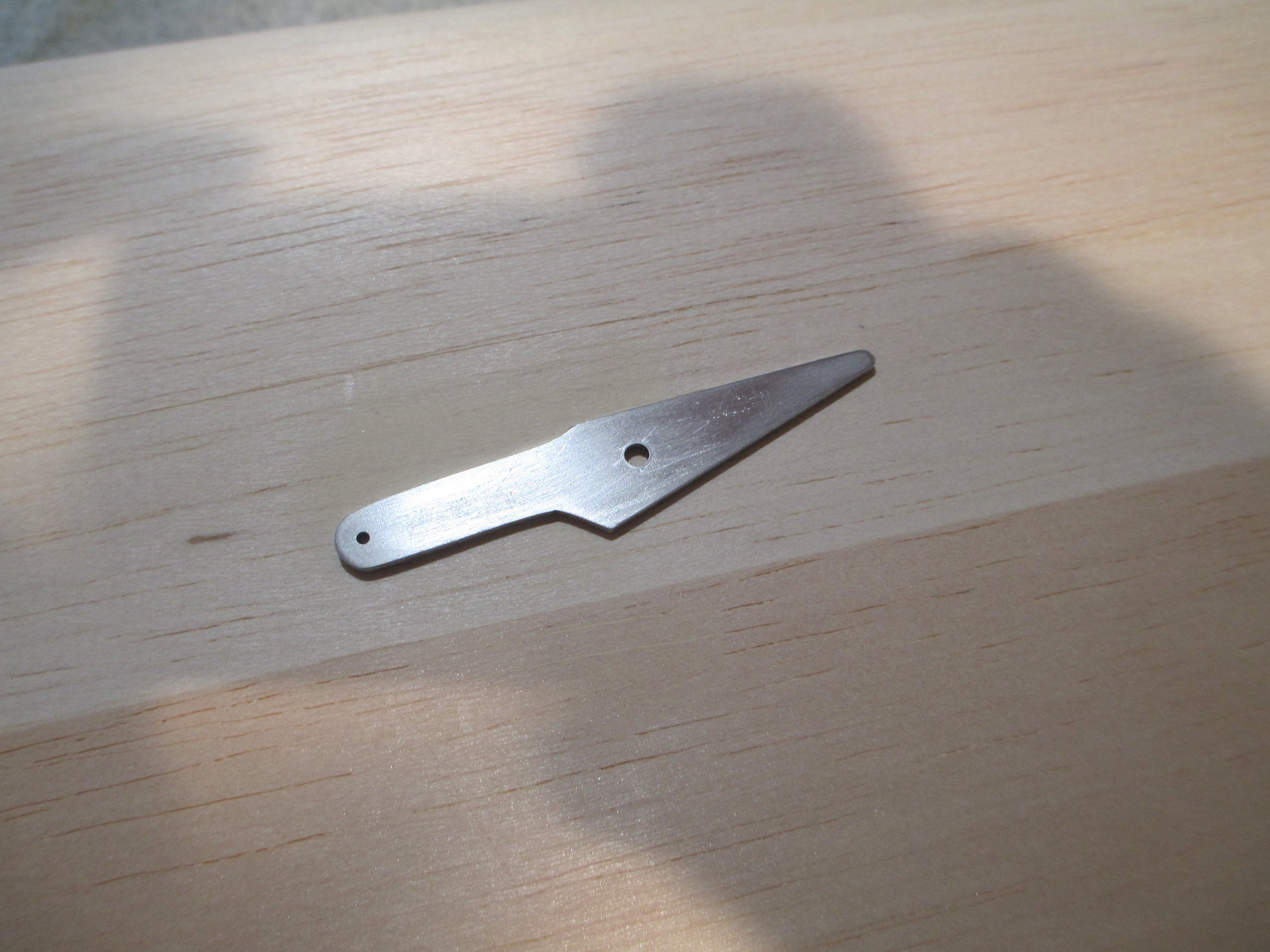
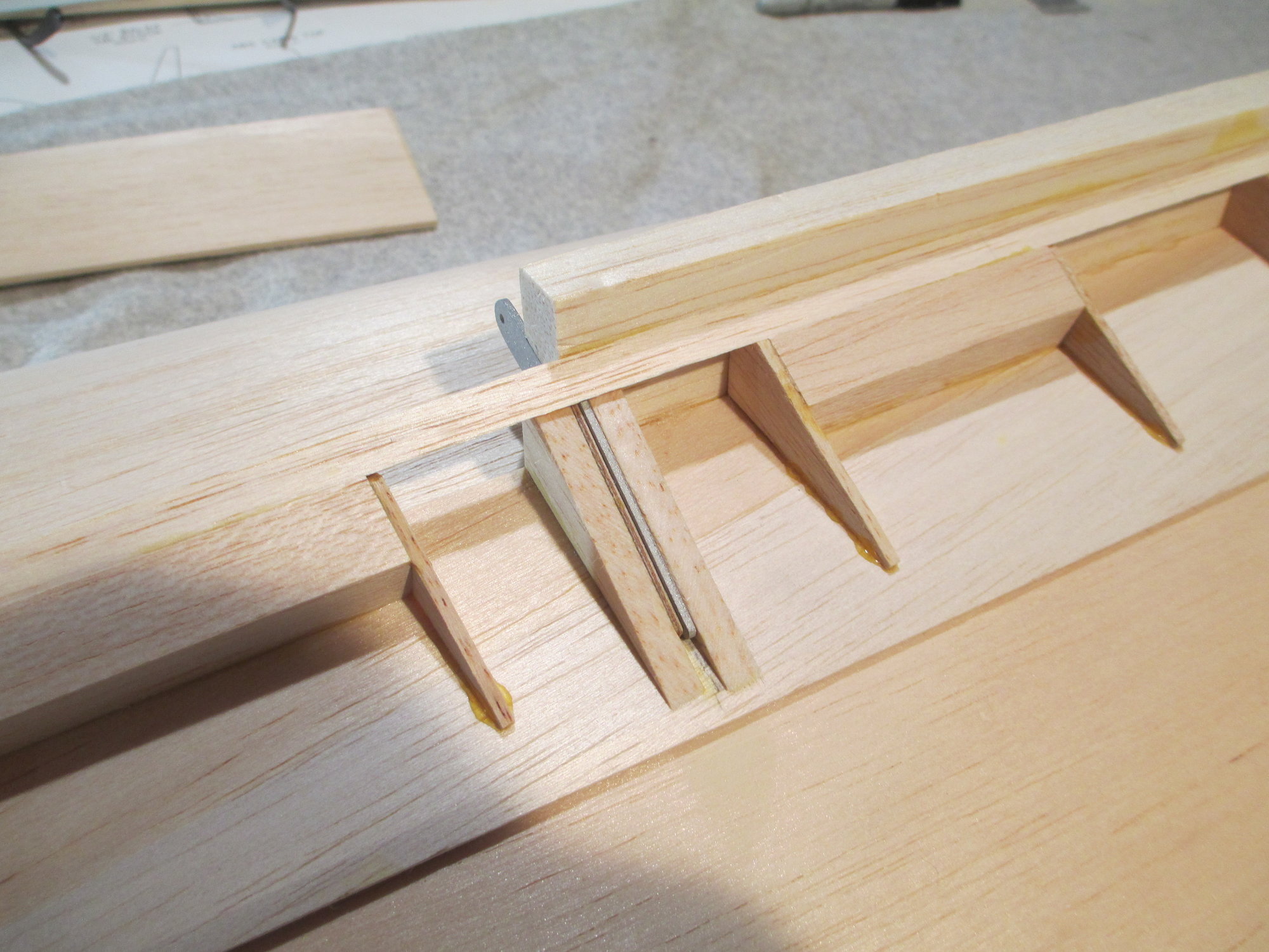
Flap horn has been glass beaded and note the hole I drilled. Once epoxied into position, this hole will in essence become an epoxy rivet locking the horn in the pocket.
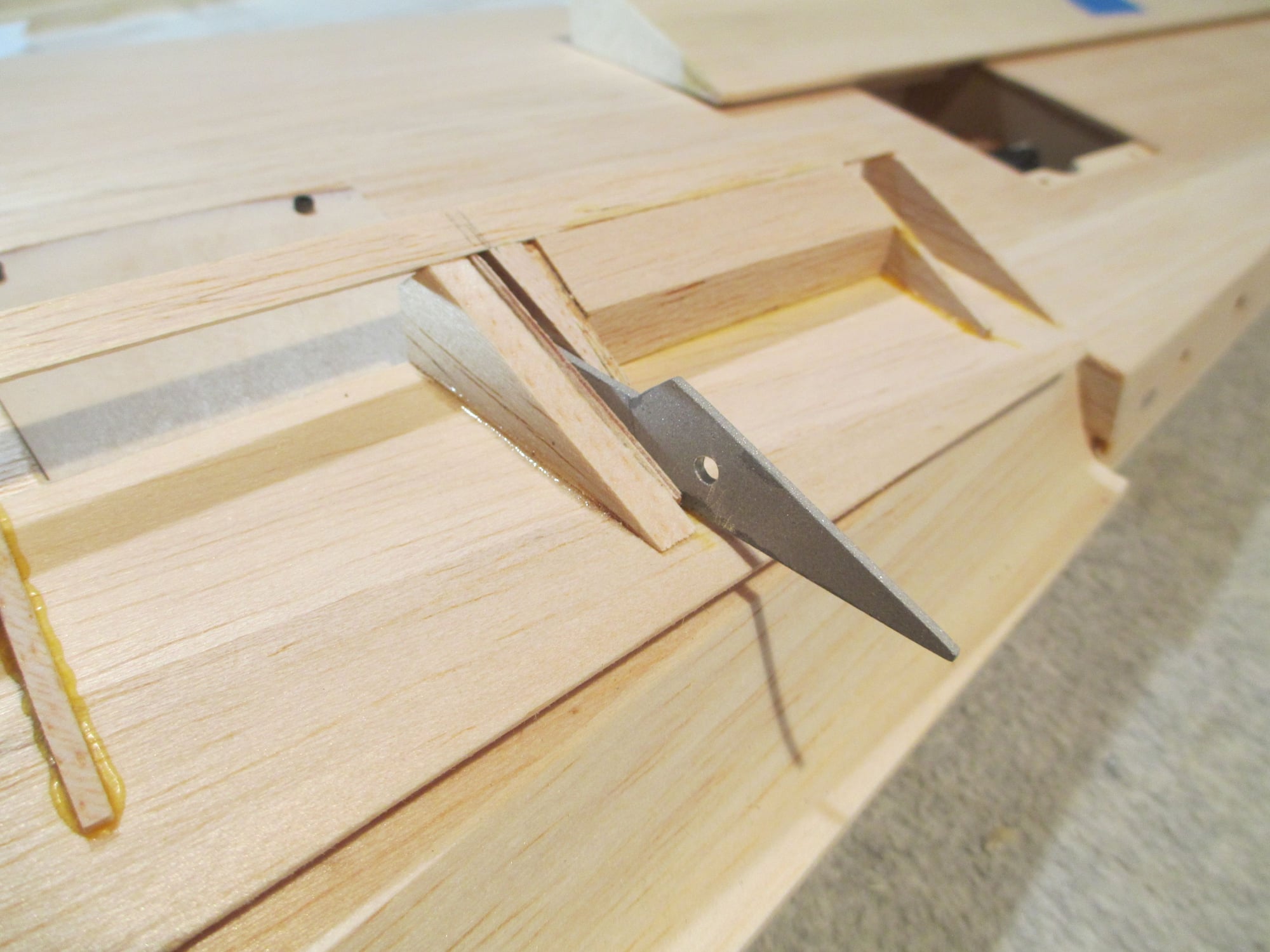
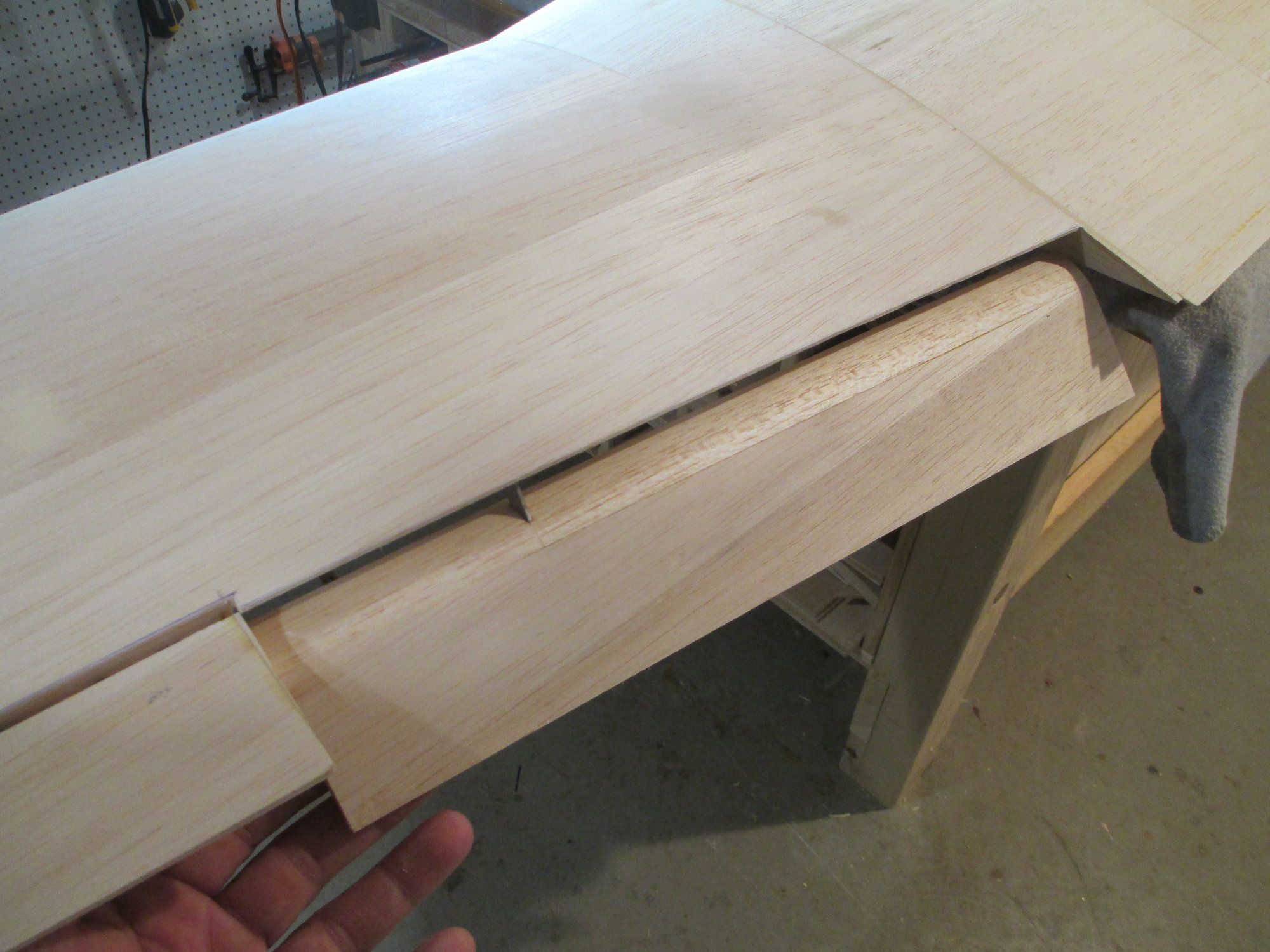
The horn is being slid into the pocket that will ultimately hold it in place.
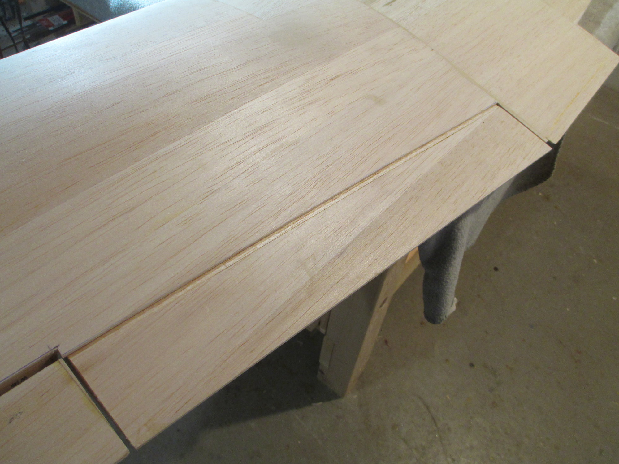
With the horn in place I can notch the flap's leading edge so it will fit around the horn.
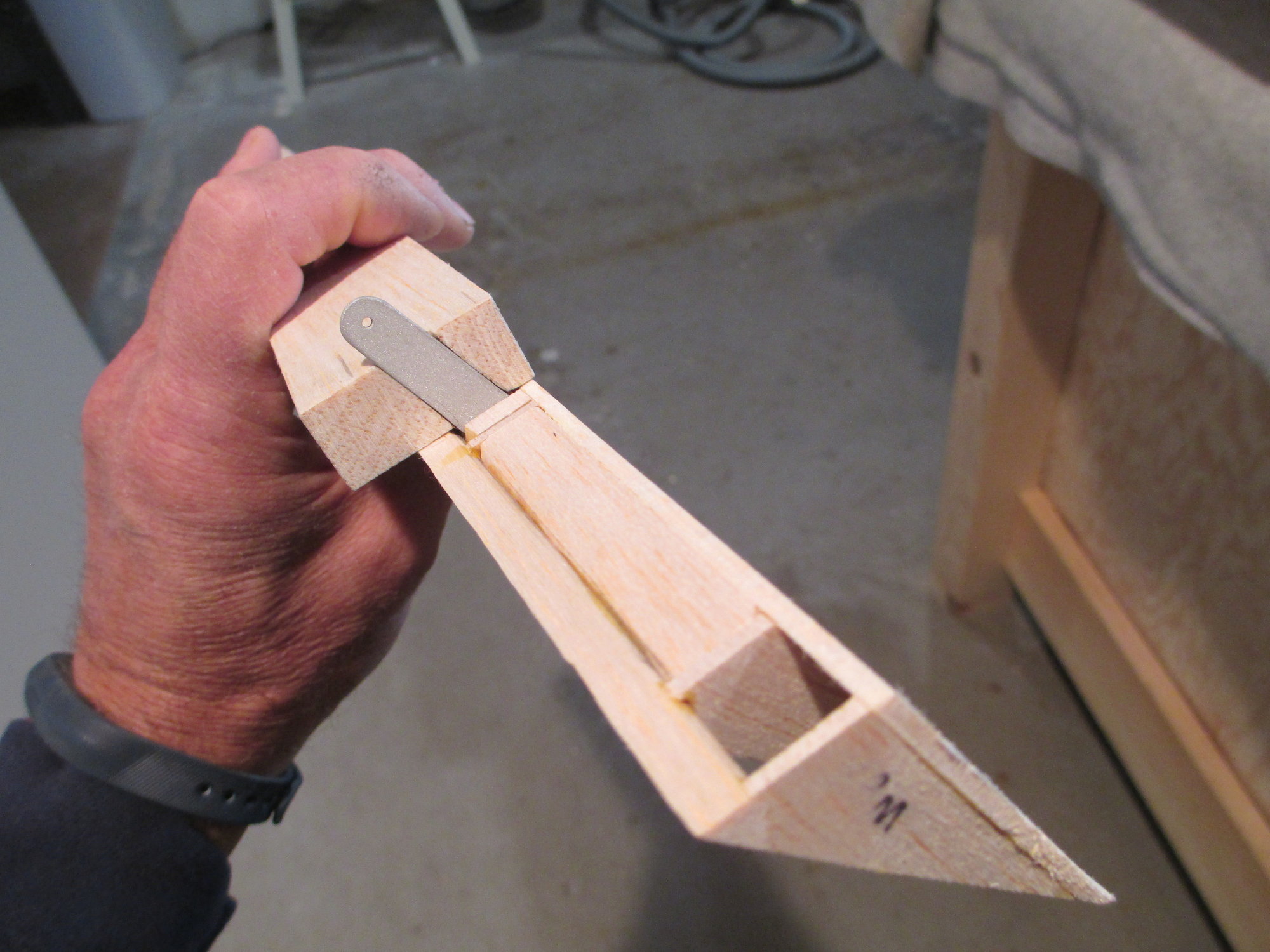
I cut the leading edge into two pieces to simplify making the notch. I will not be epoxying the horn until after the leading edge is shaped rather than having to work around the horn...
Last edited by VincentJ; 10-27-2019 at 12:30 AM.
10-26-2019, 11:19 AM
#383
Thread Starter
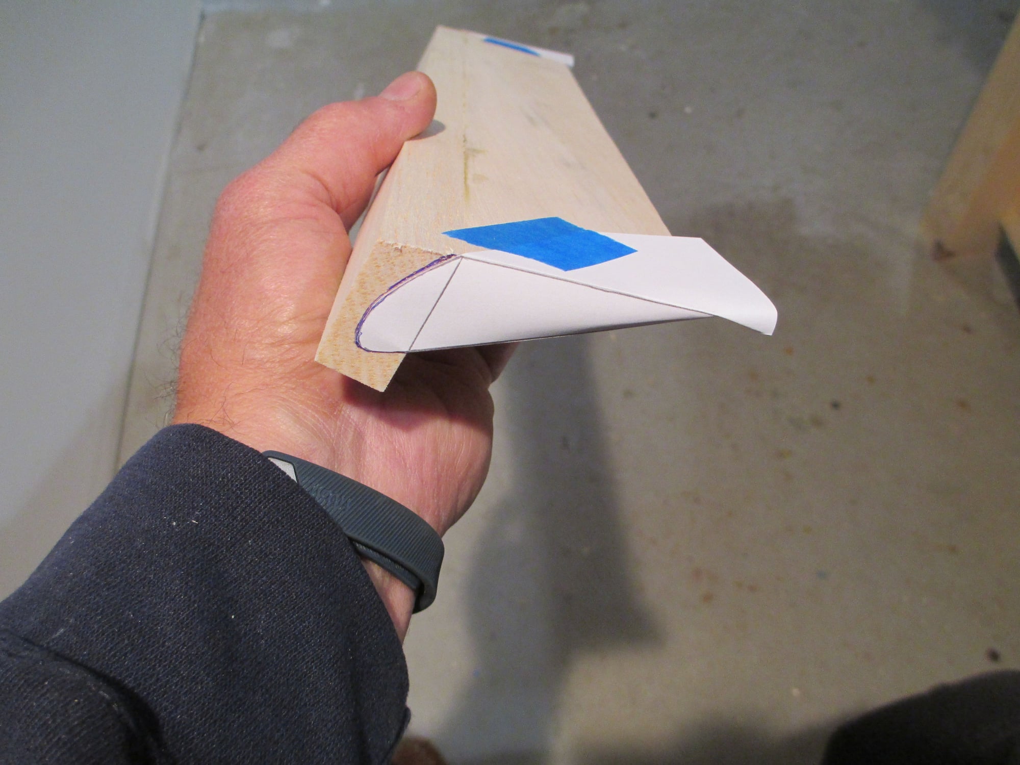
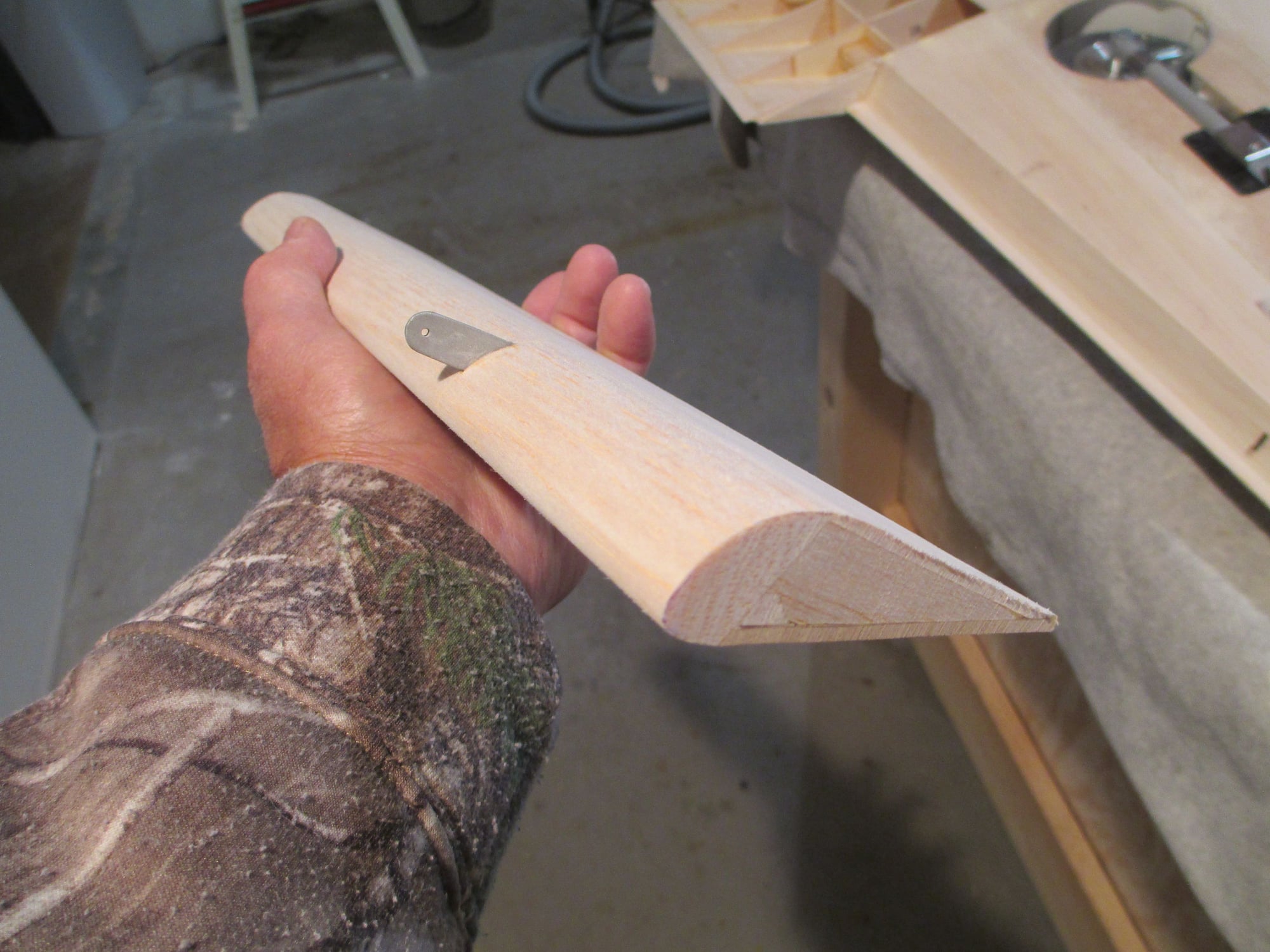
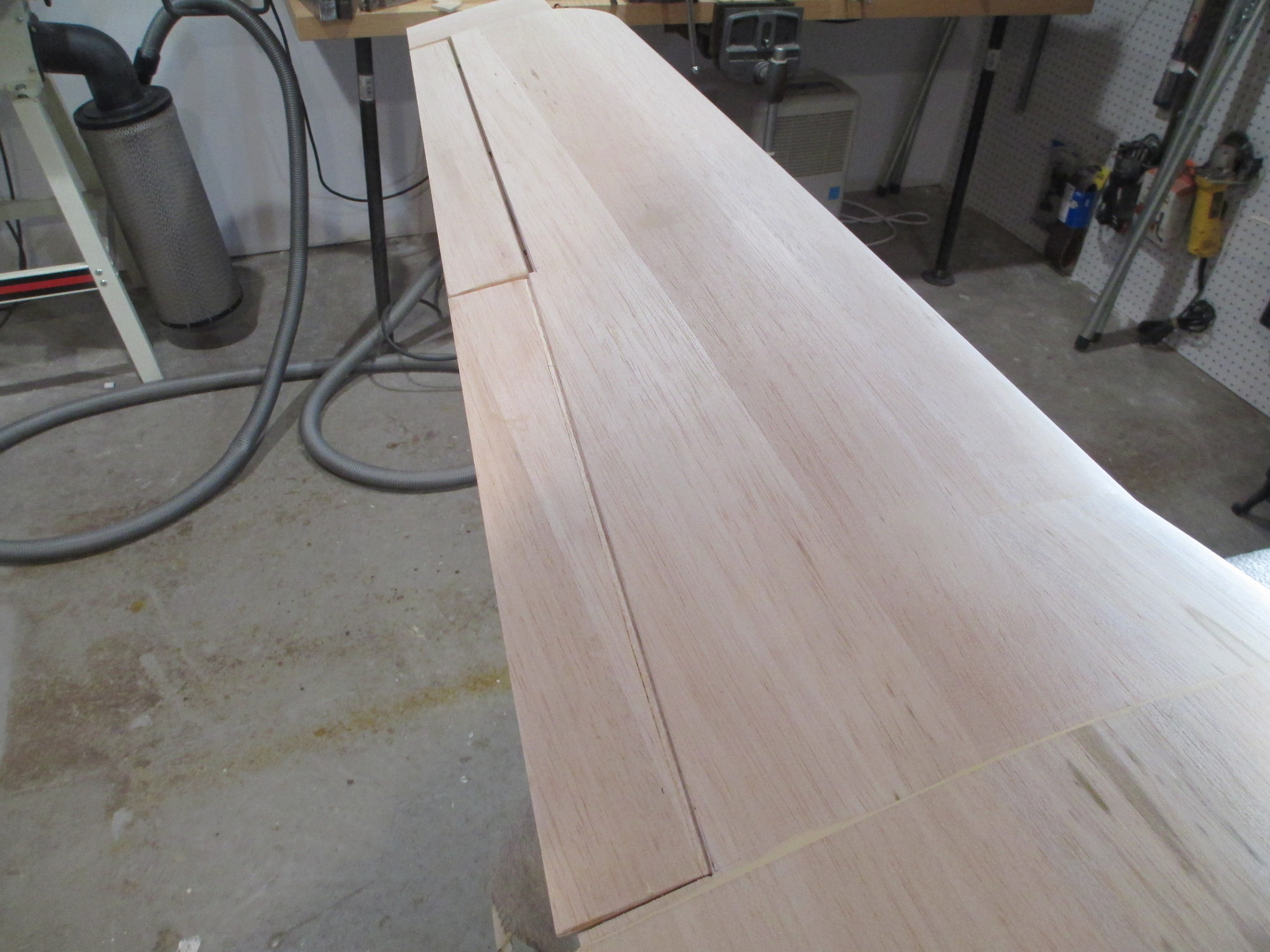
I traced off the plans and cut out a template of the flap's leading edge profile.
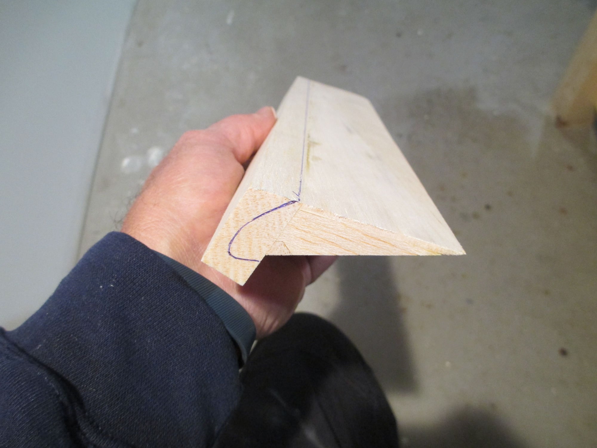
Using a blue ink pen I traced the profile onto each end, then the template was removed. You may be wondering why the ink profile extends beyond the bottom of the flap. Remember , that side of the flap has not yet been sheeted (3/32").
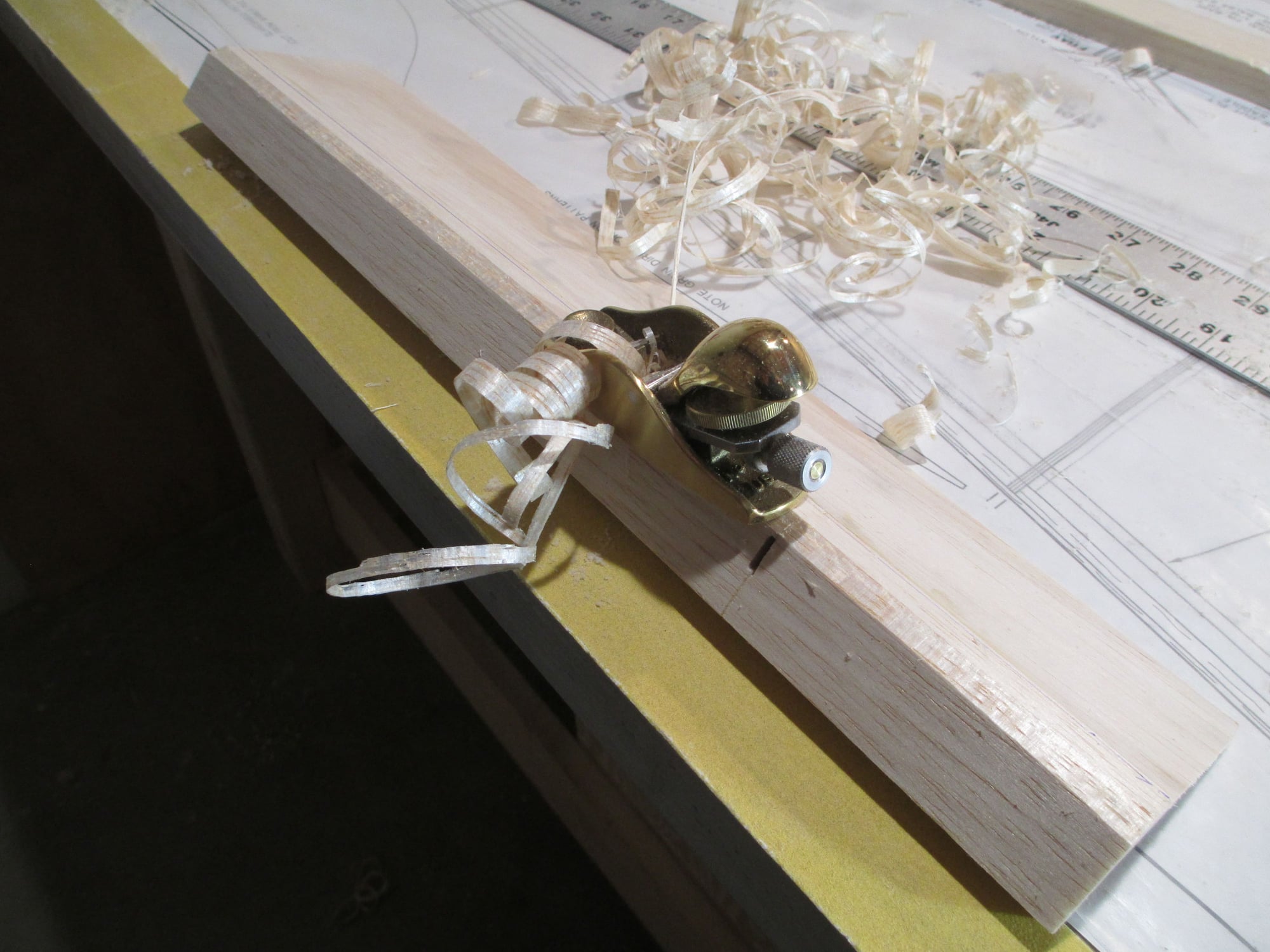
I always enjoy using my hand plane... making some nice balsa curls!
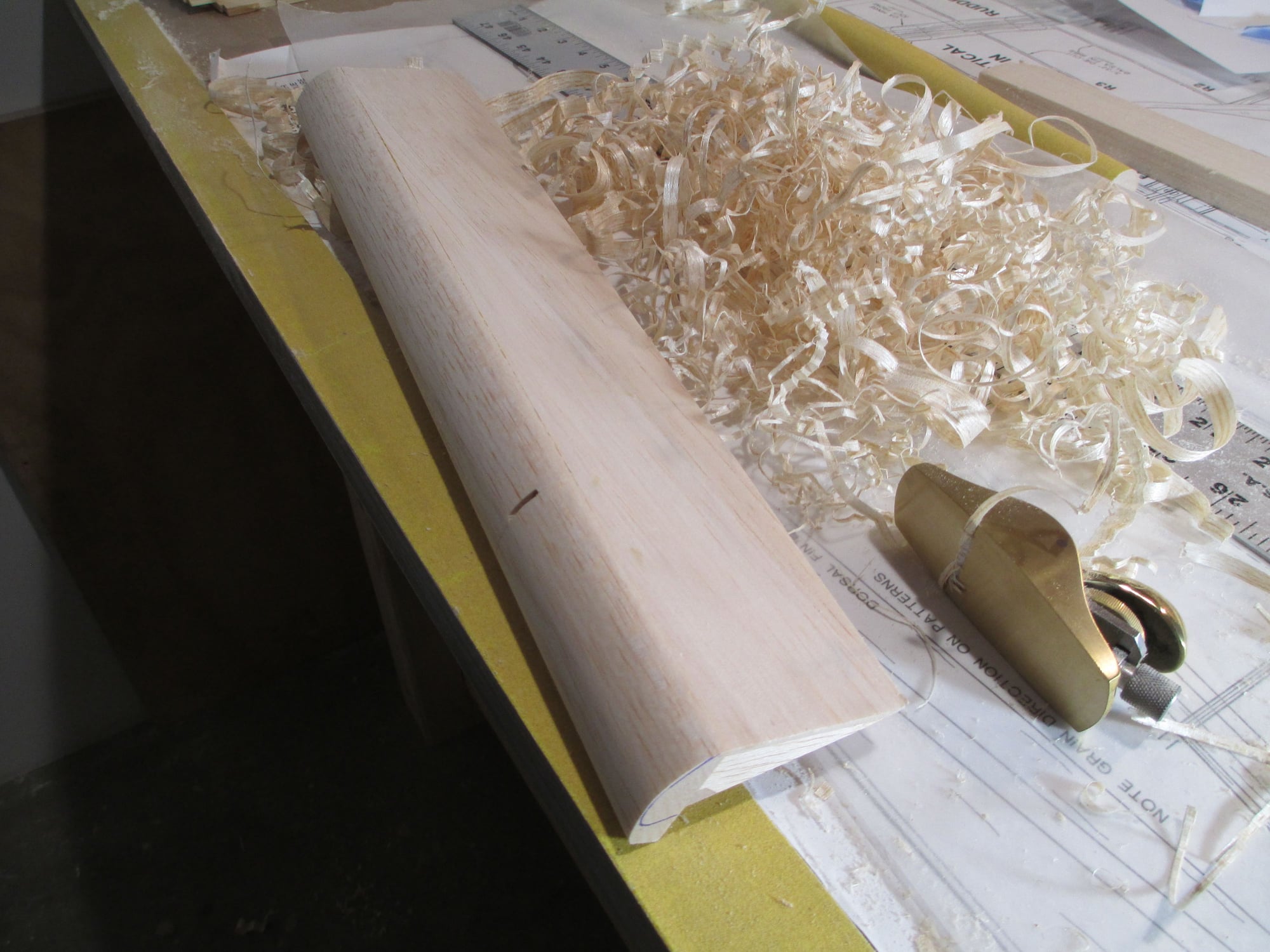
You can better understand now why I chose not to install the flap horn. It would have made the job so much more difficult.
It's time to mix-up some epoxy and permanently install the horn.
Once cured, I will be able to sheet the remaining bit of the flap and continue shaping the bottom half of the LE.
Last edited by VincentJ; 10-27-2019 at 12:44 AM.
10-27-2019, 09:28 AM
#385
Thread Starter
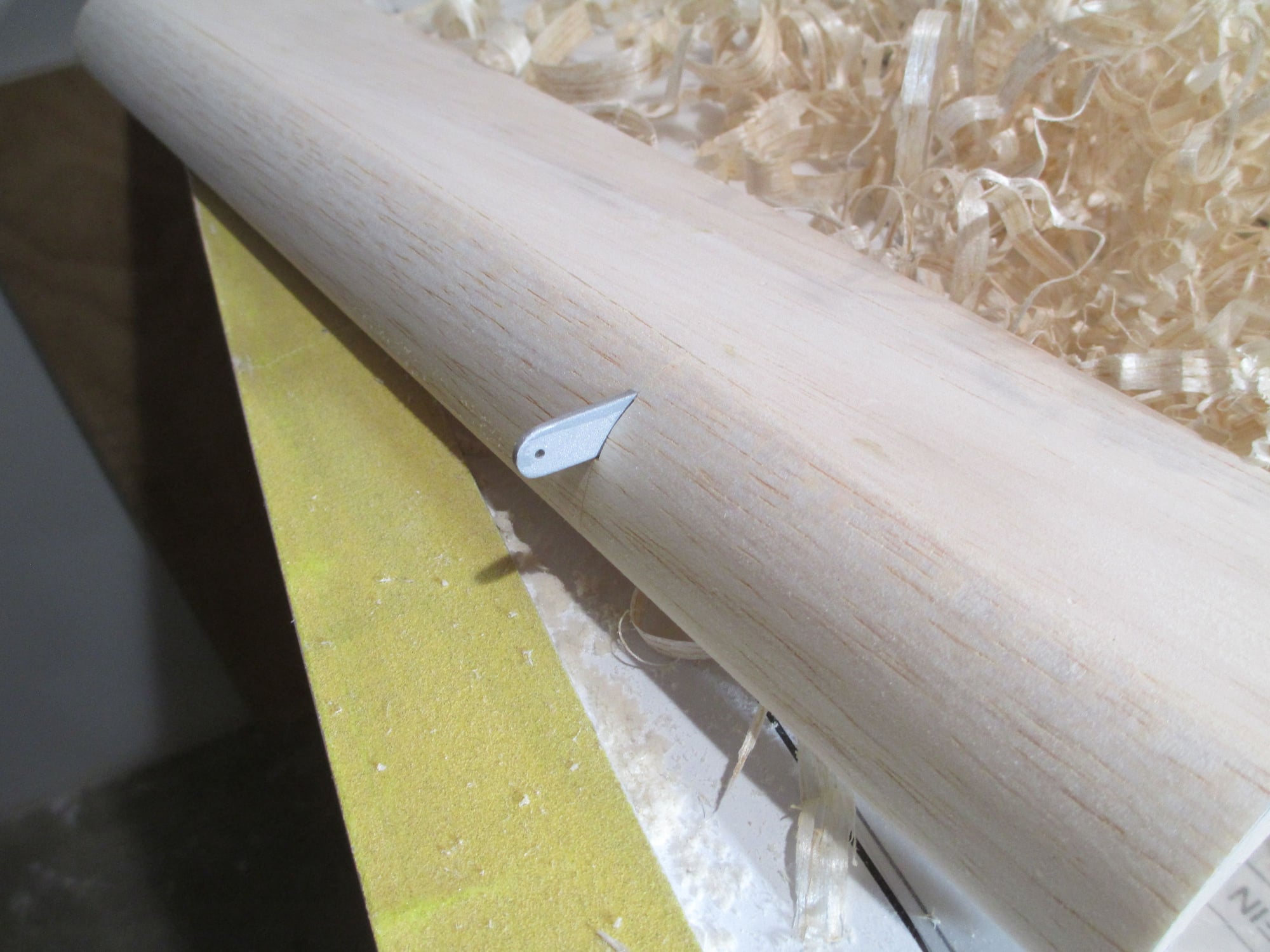
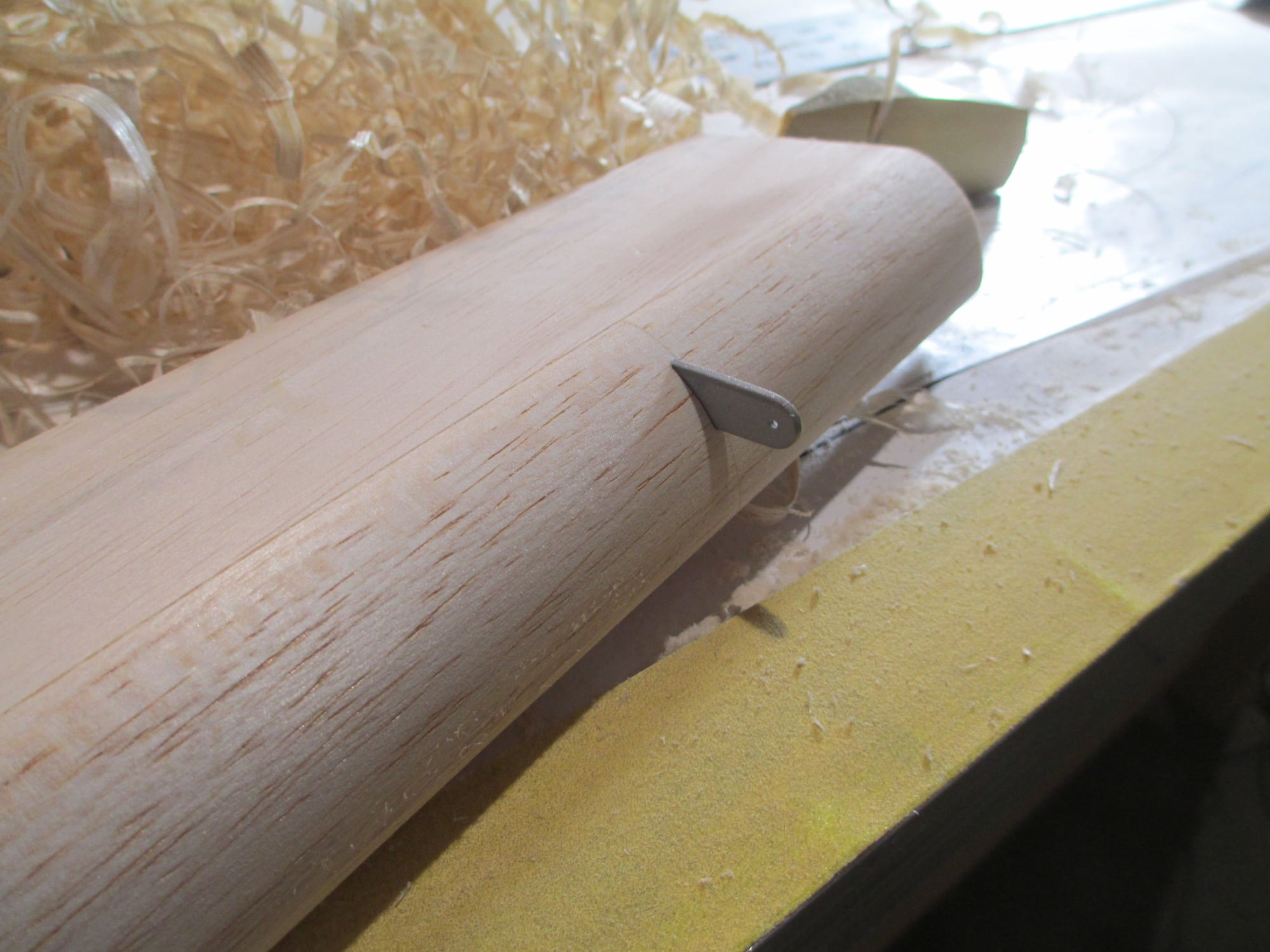
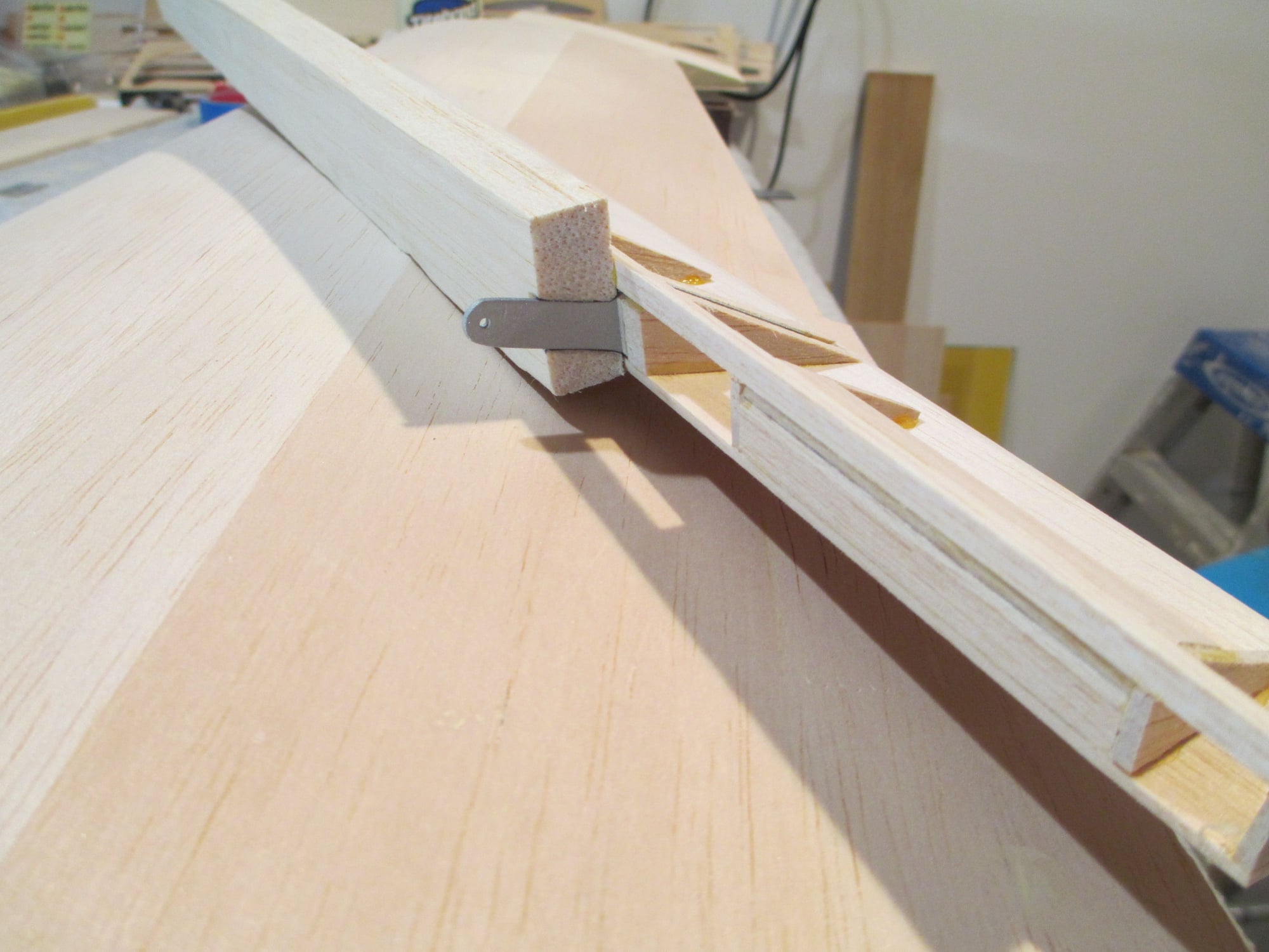
Profile is pretty close spot-on. End caps still need to be glued on...
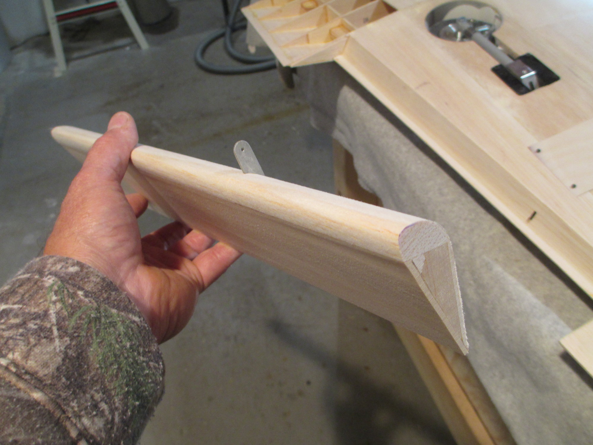
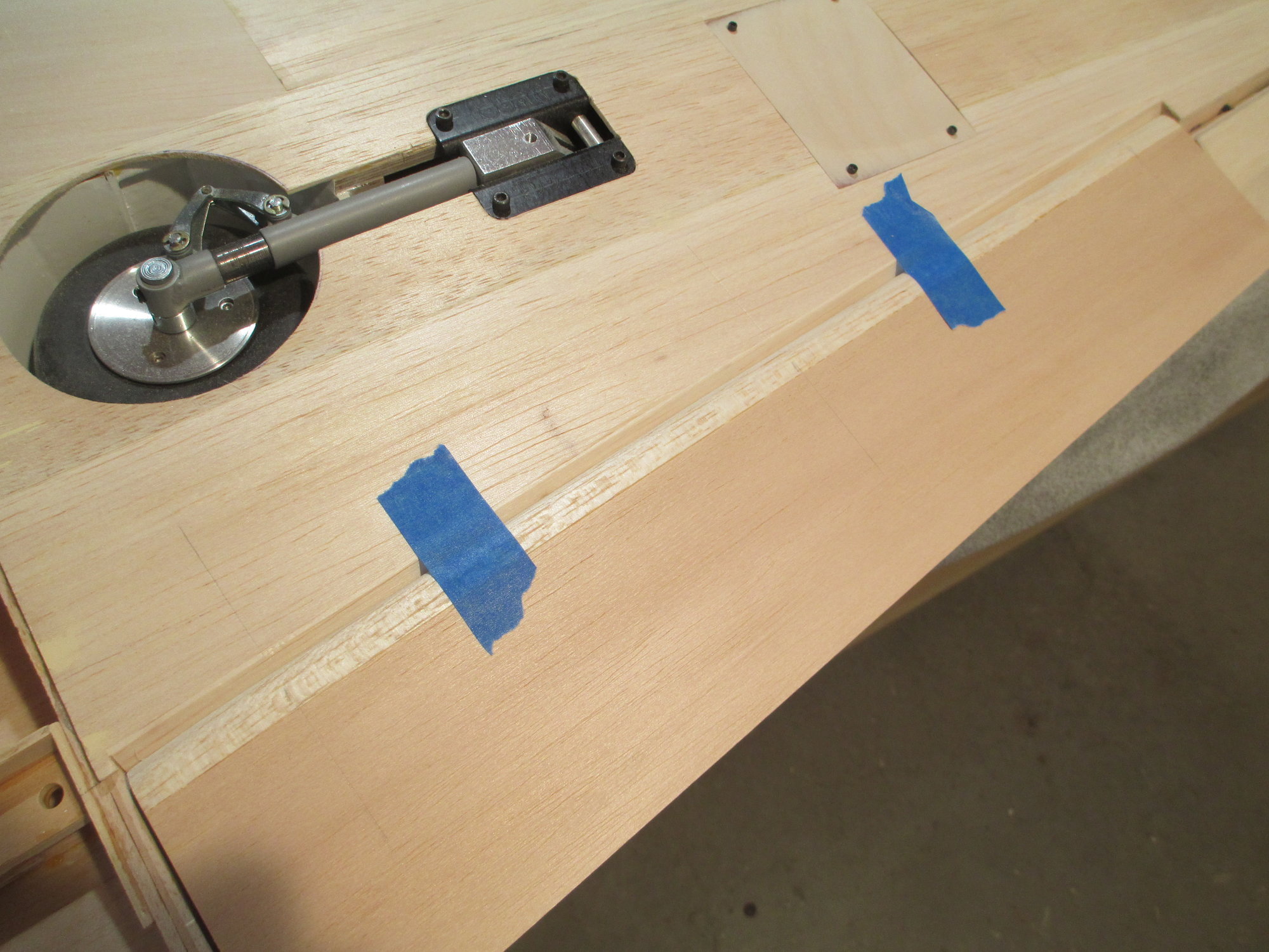
It's time to hinge this flap.
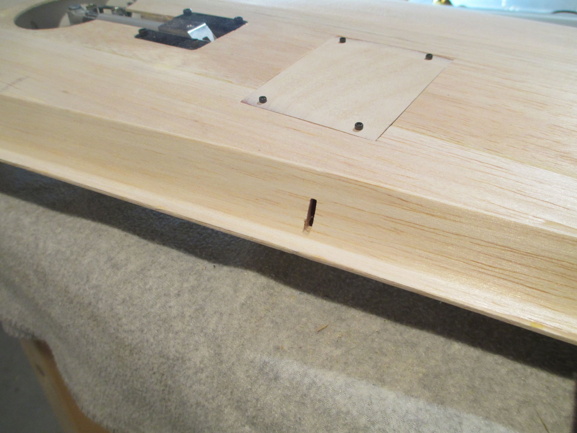
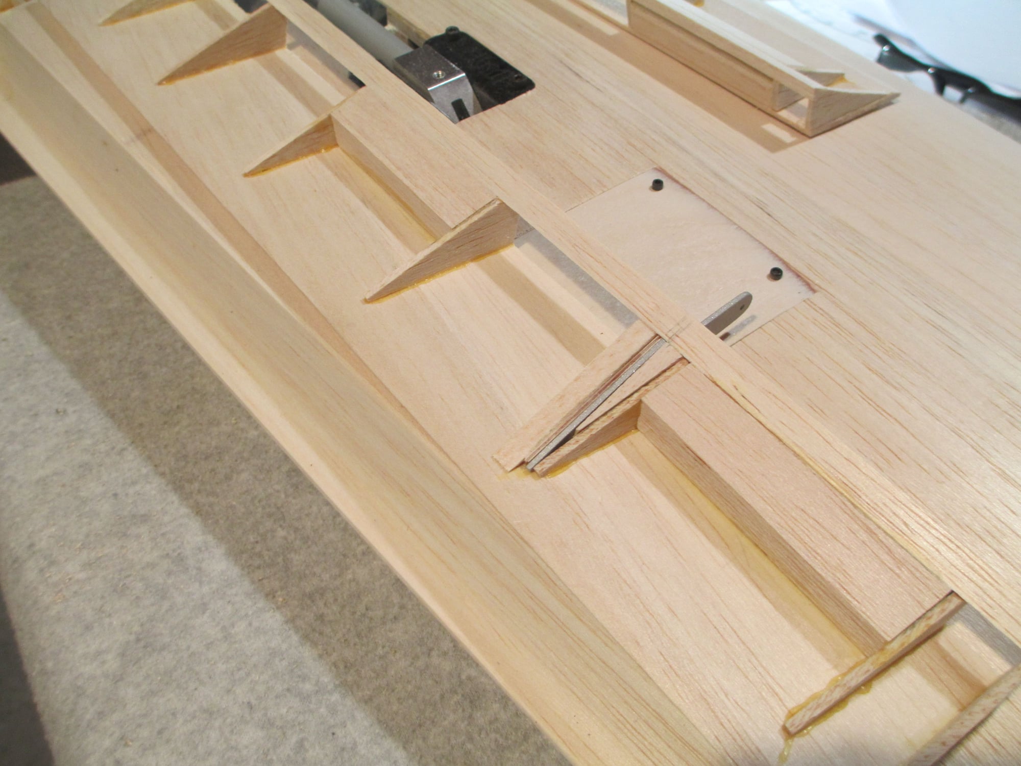
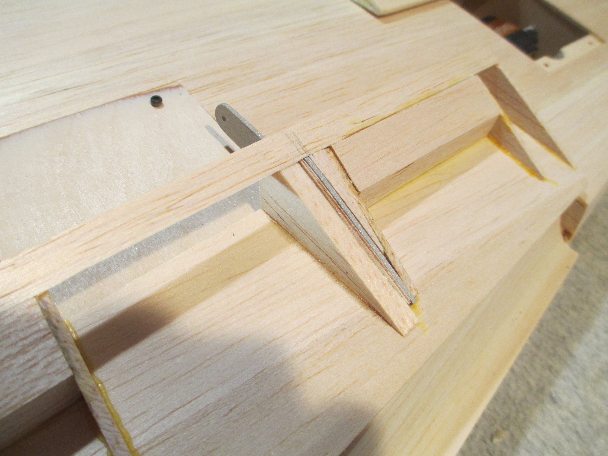
Slot cut into the wing's trailing edge to allow the horn to pass through. It will need to be widened up later.
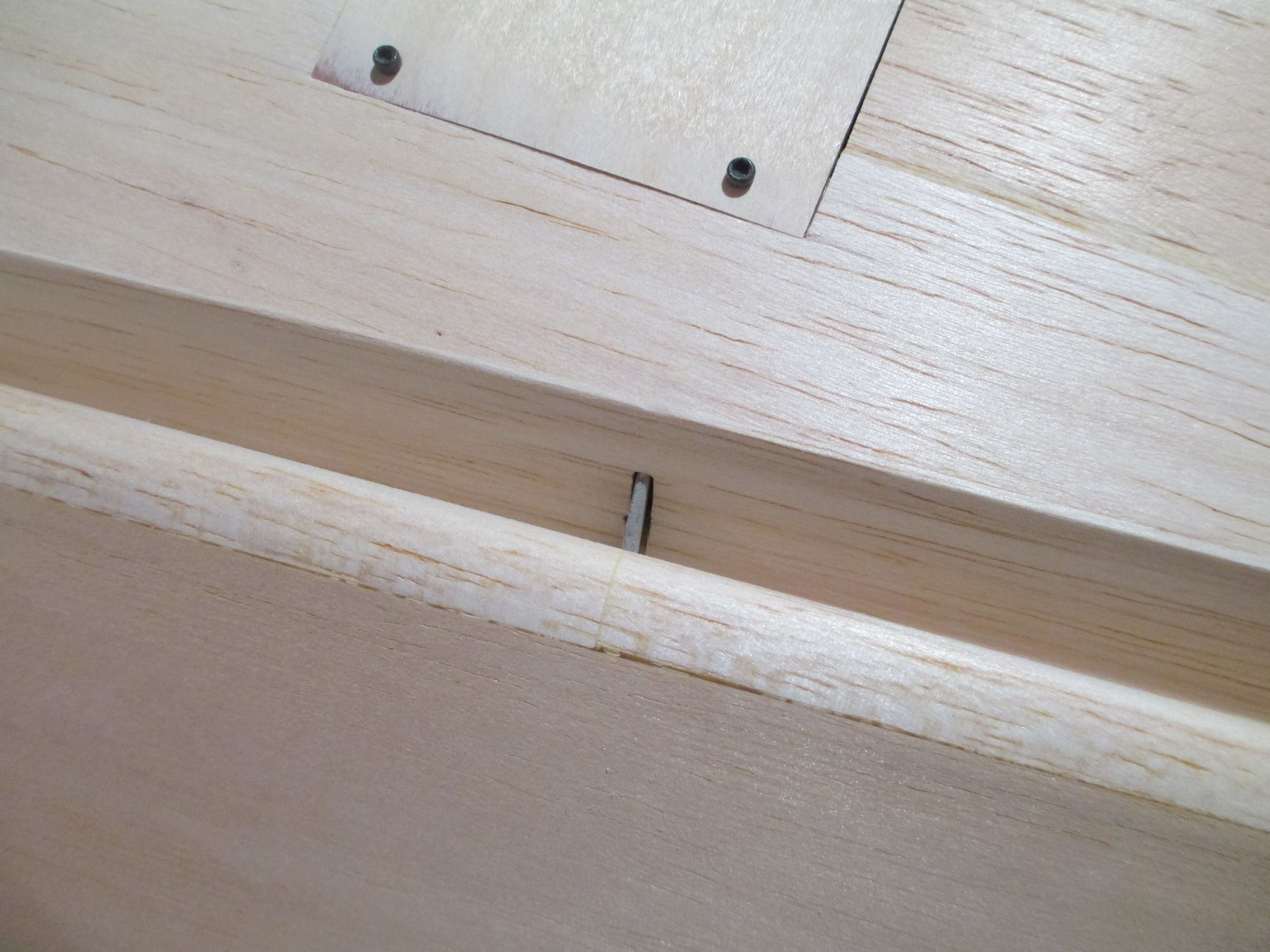
Close-up of the horn passing through the slot.
10-28-2019, 02:16 AM
#386
Thread Starter
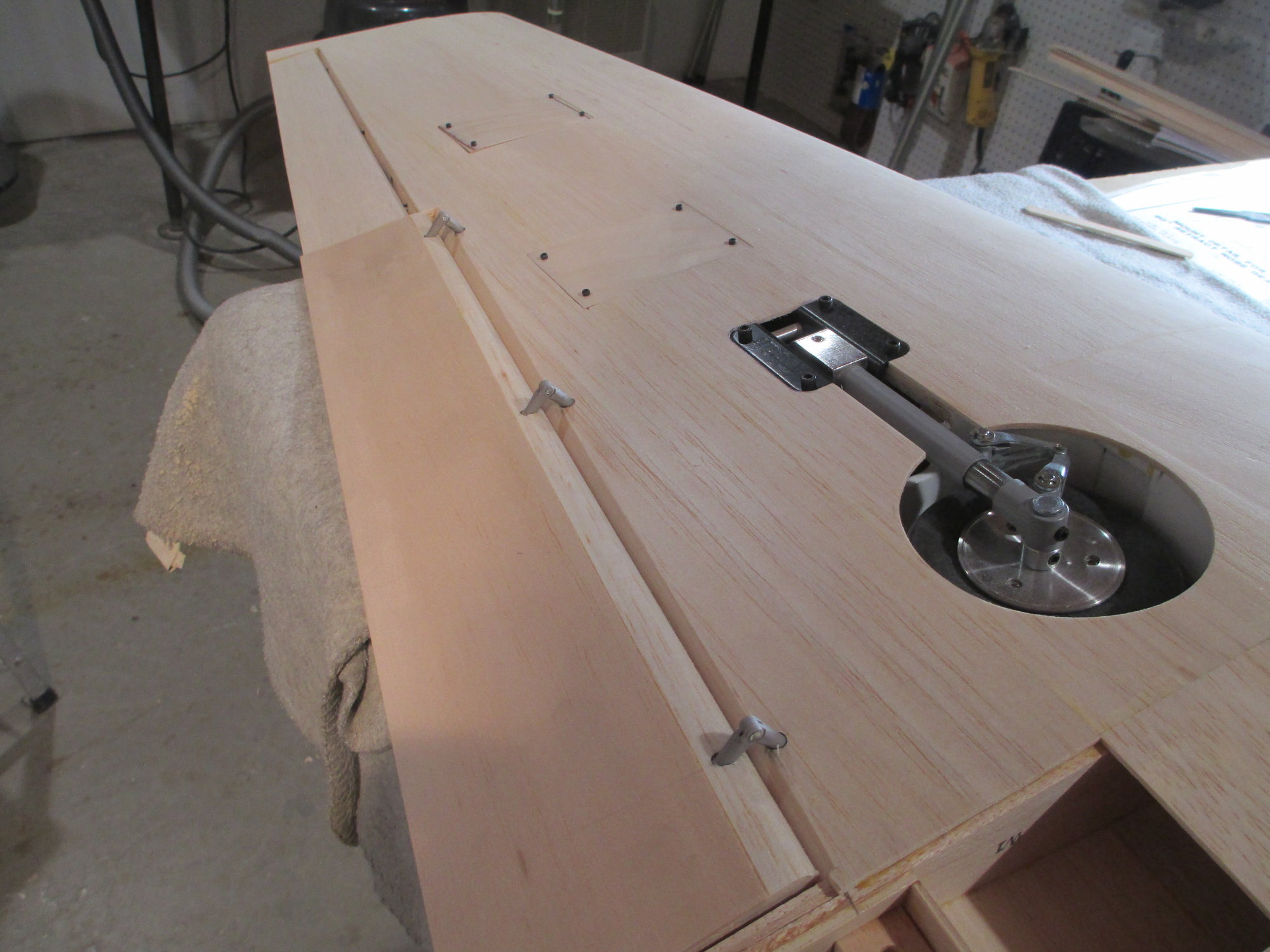
Hinging the flaps starts by marking careful measurements onto the bottom of the wing and flap.
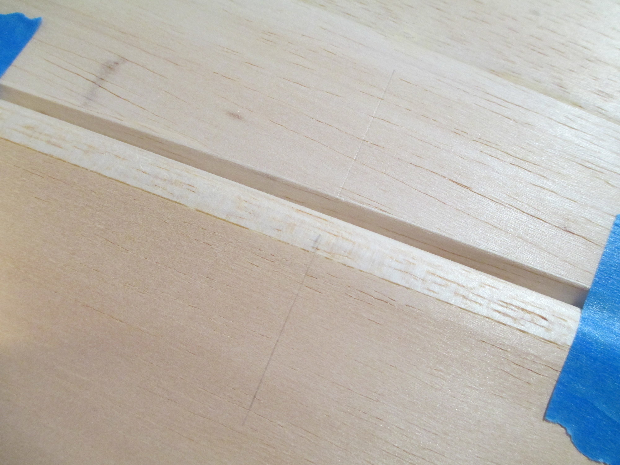
I used a pencil this time because I wanted a nice crisp thin line to gauge my hinge guide tool off of.
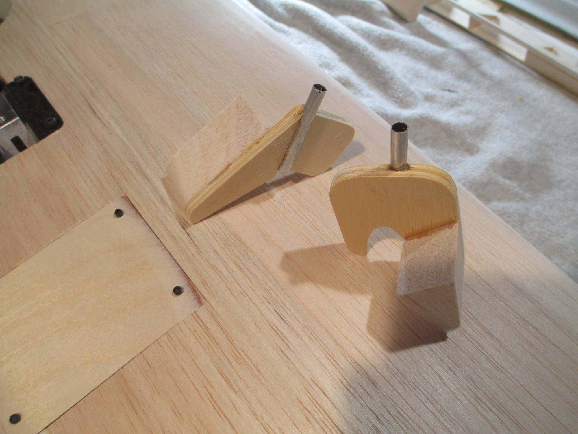
These are my modified hinge drill guide tools for both the wing and the flap. I epoxied an aluminum 7/32" tube to the center of the guide.
Wanting a cleaner hole, I opted against using a drill bit. Instead I used a length of 3/16" brass tubing sharpened at one end chucked in my hand drill. Note the black marks on the tubing which tell me how deep the hole should be. The added balsa glued to the guide base makes the tool more stable and gives me the confidence to make a straight hole.
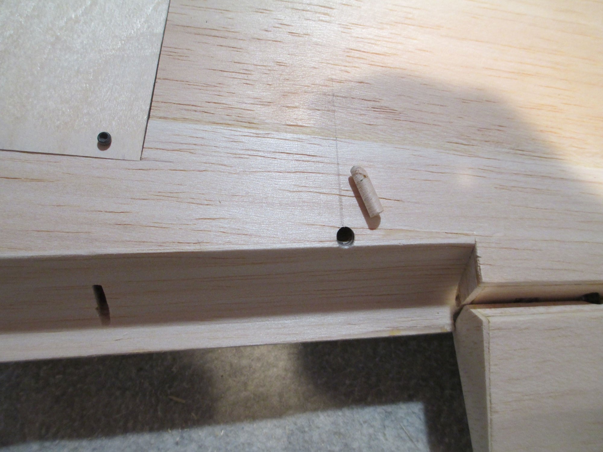
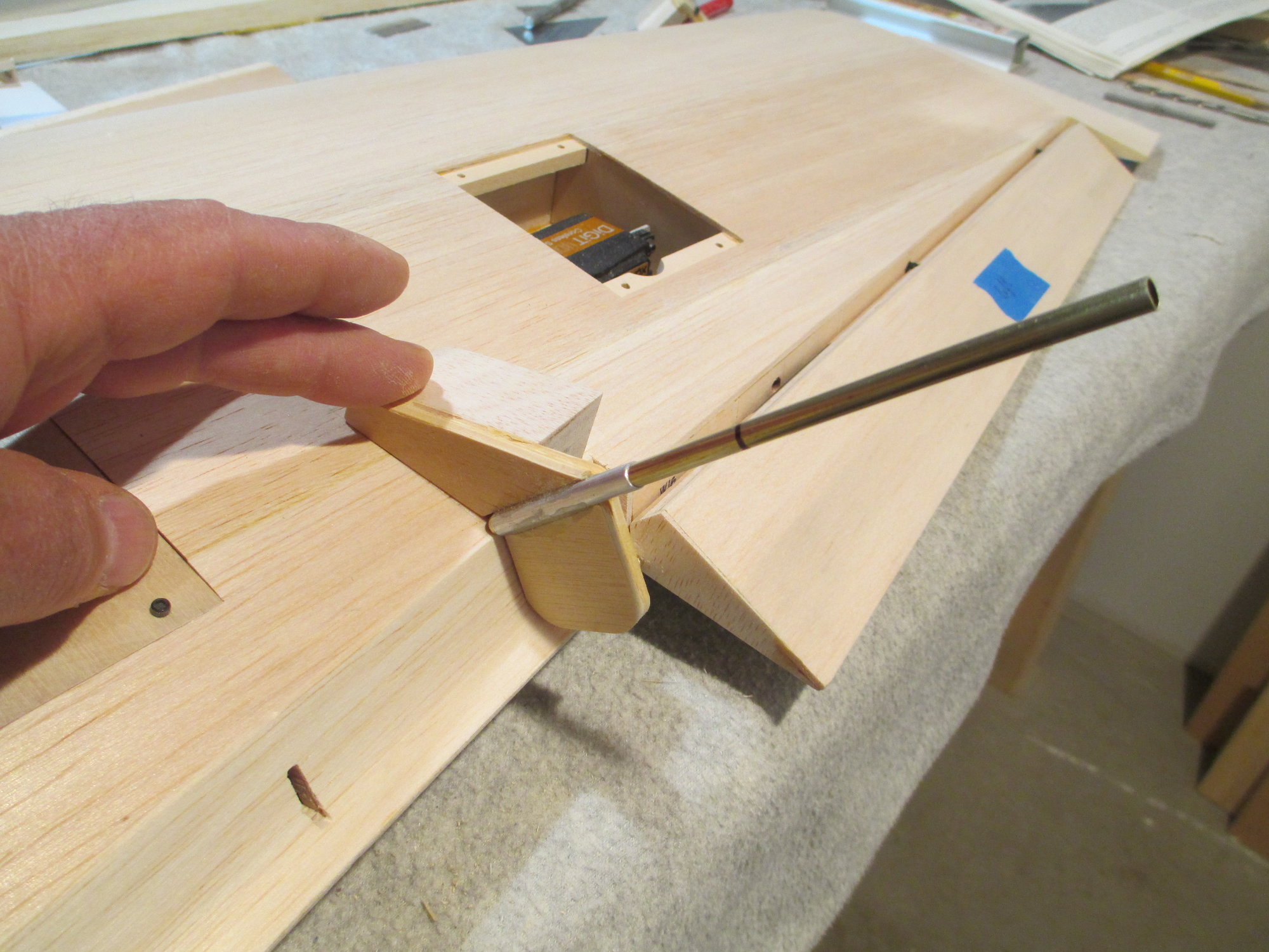
The end result is a cleaner hole. Note the balsa plug...
Before I had mentioned that I used a pencil to make a crisp thin line on the sheeting surface. I'm aligning the edge of the drill guide right up to the pencil line, which is the exact center line of the aluminum guide tube. This just gives me a little better accuracy.
Last edited by VincentJ; 10-28-2019 at 02:25 AM.
10-29-2019, 12:57 PM
#388
Thread Starter
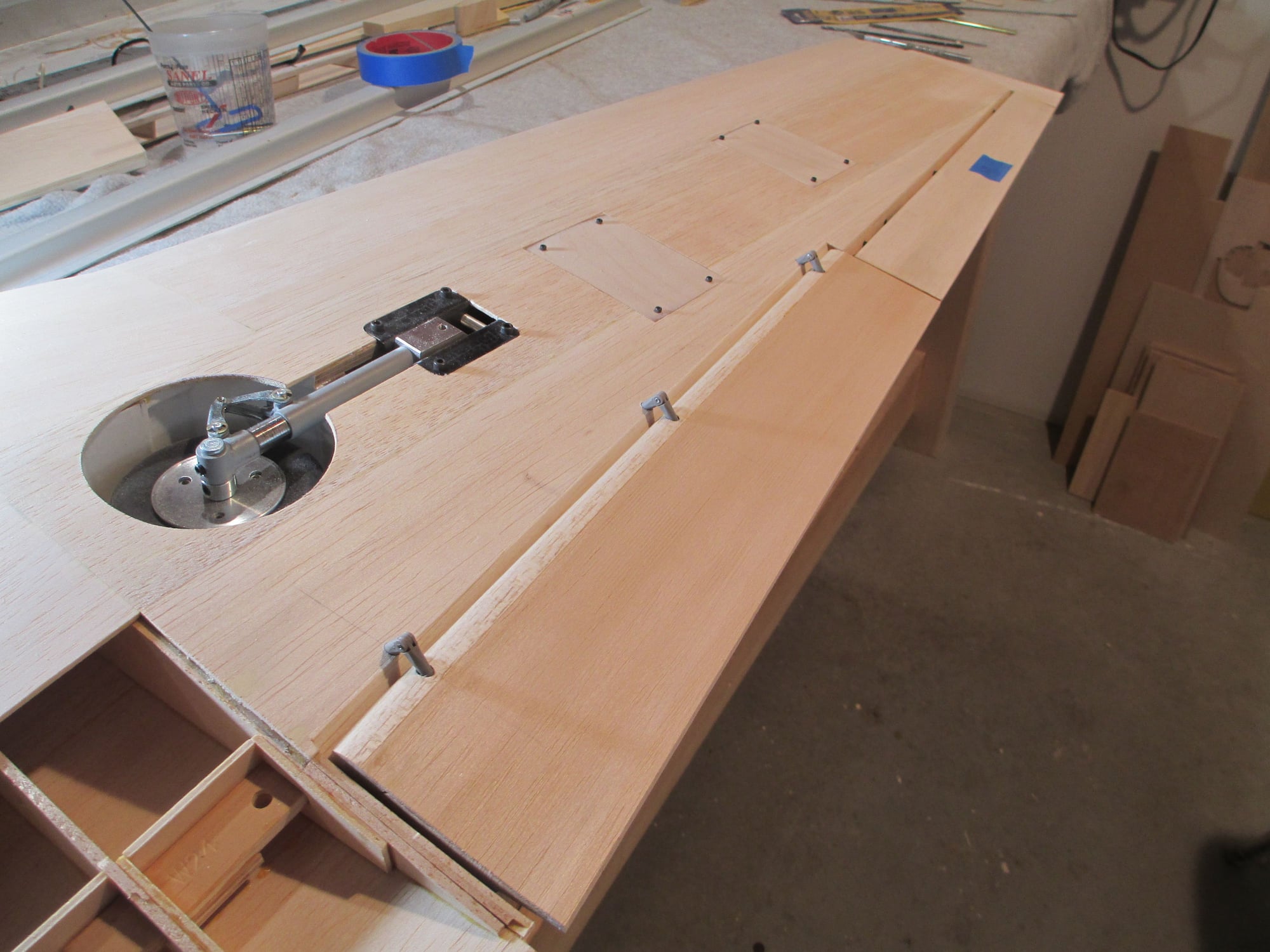
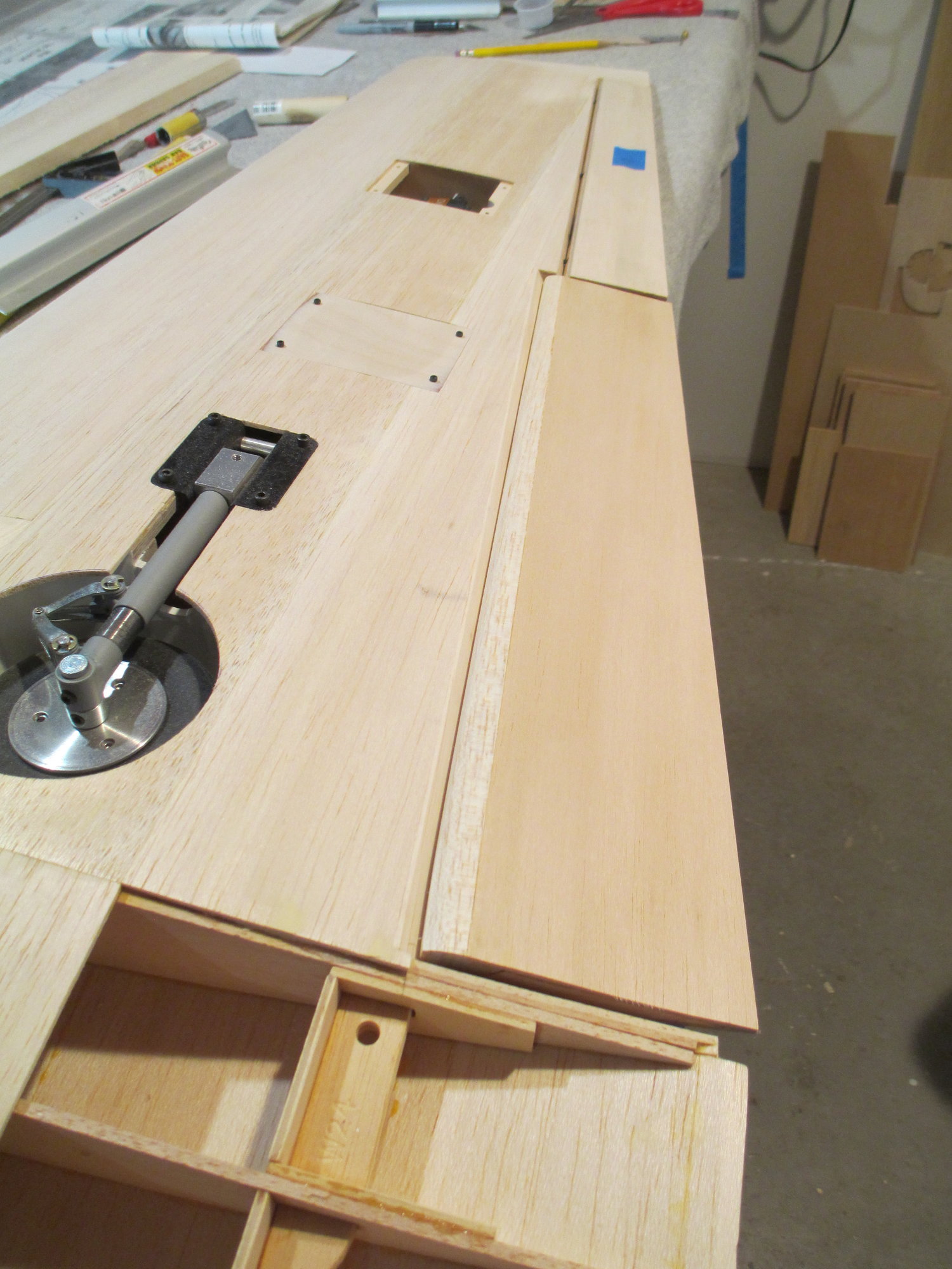
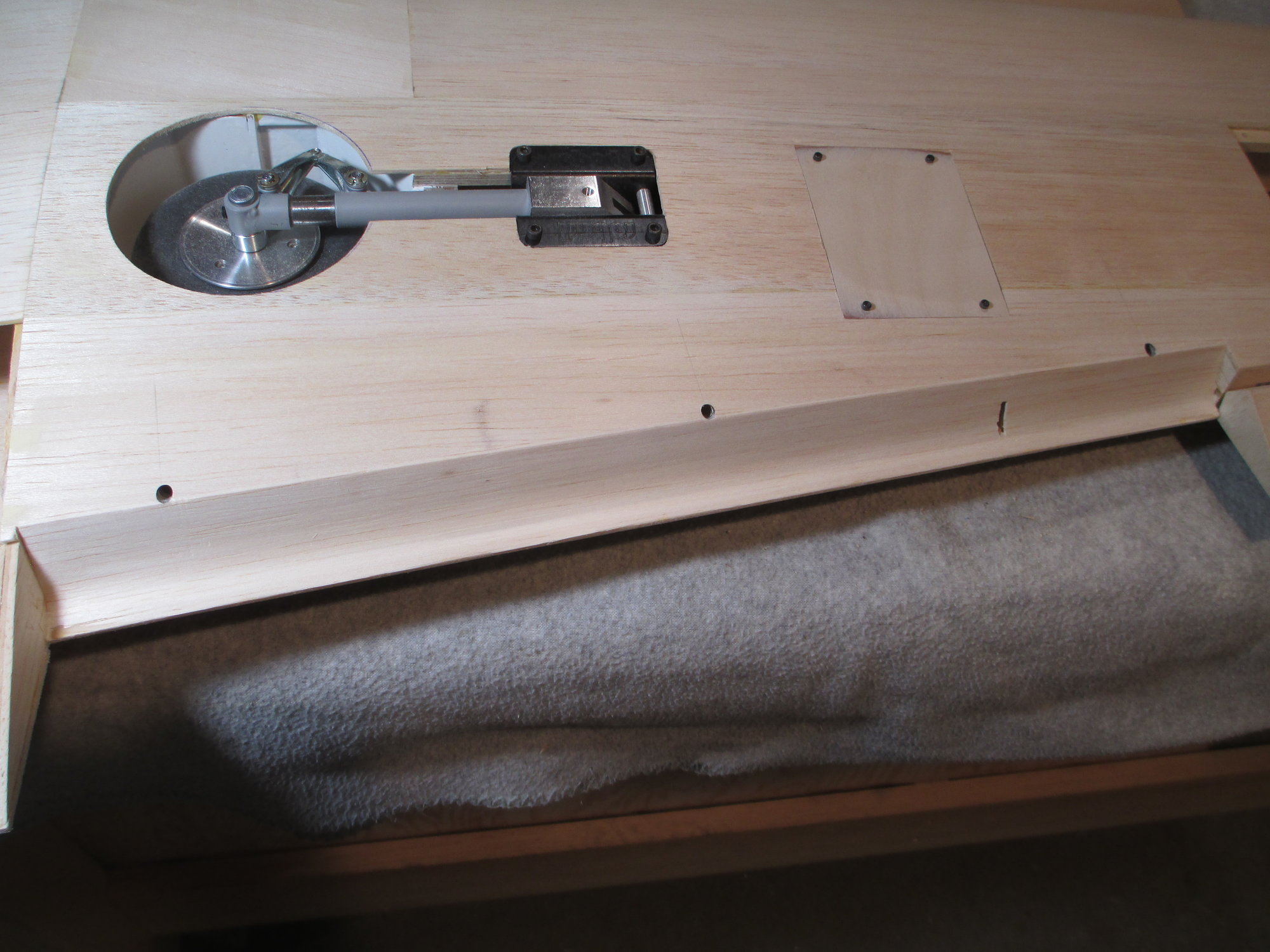
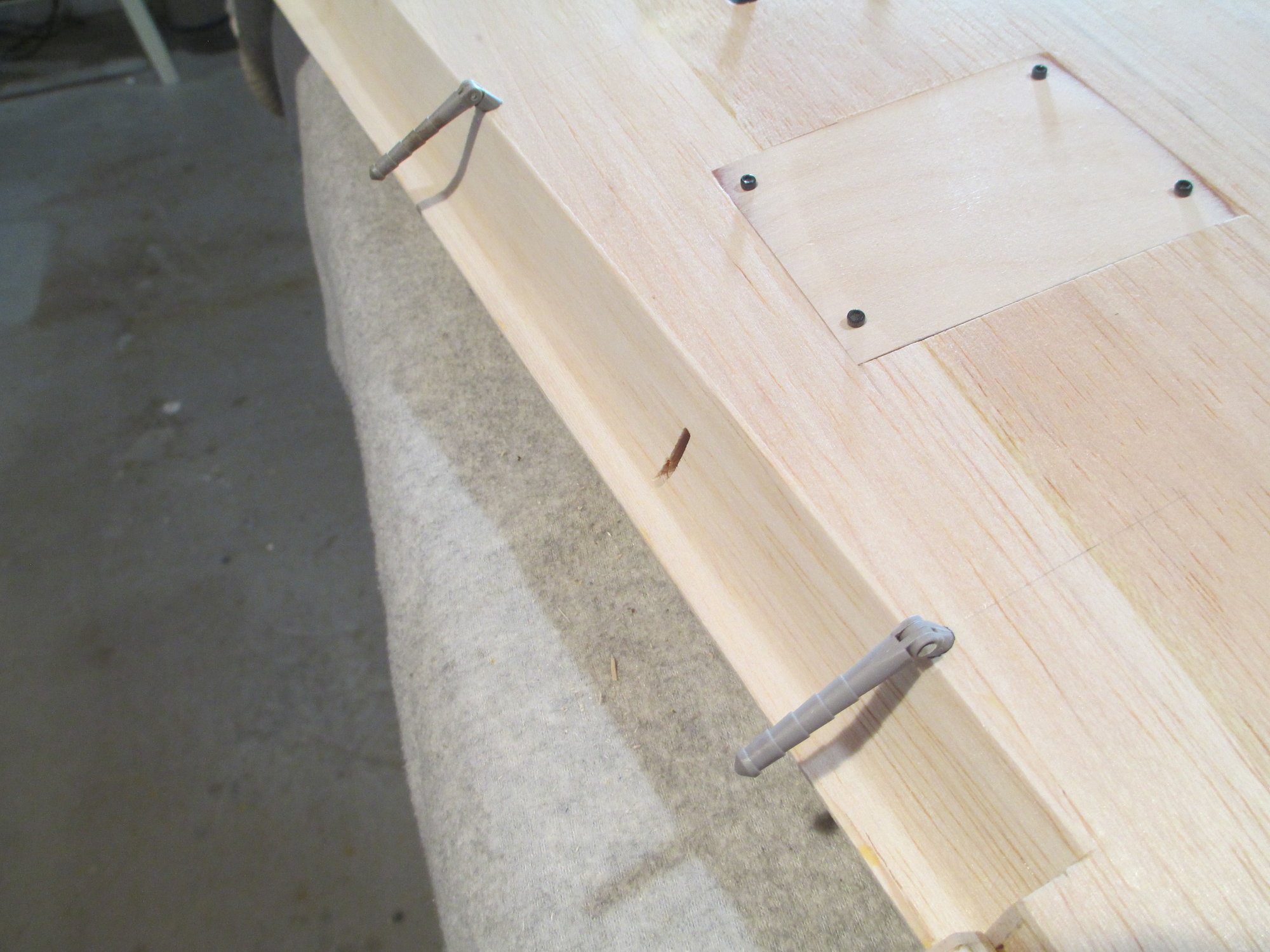
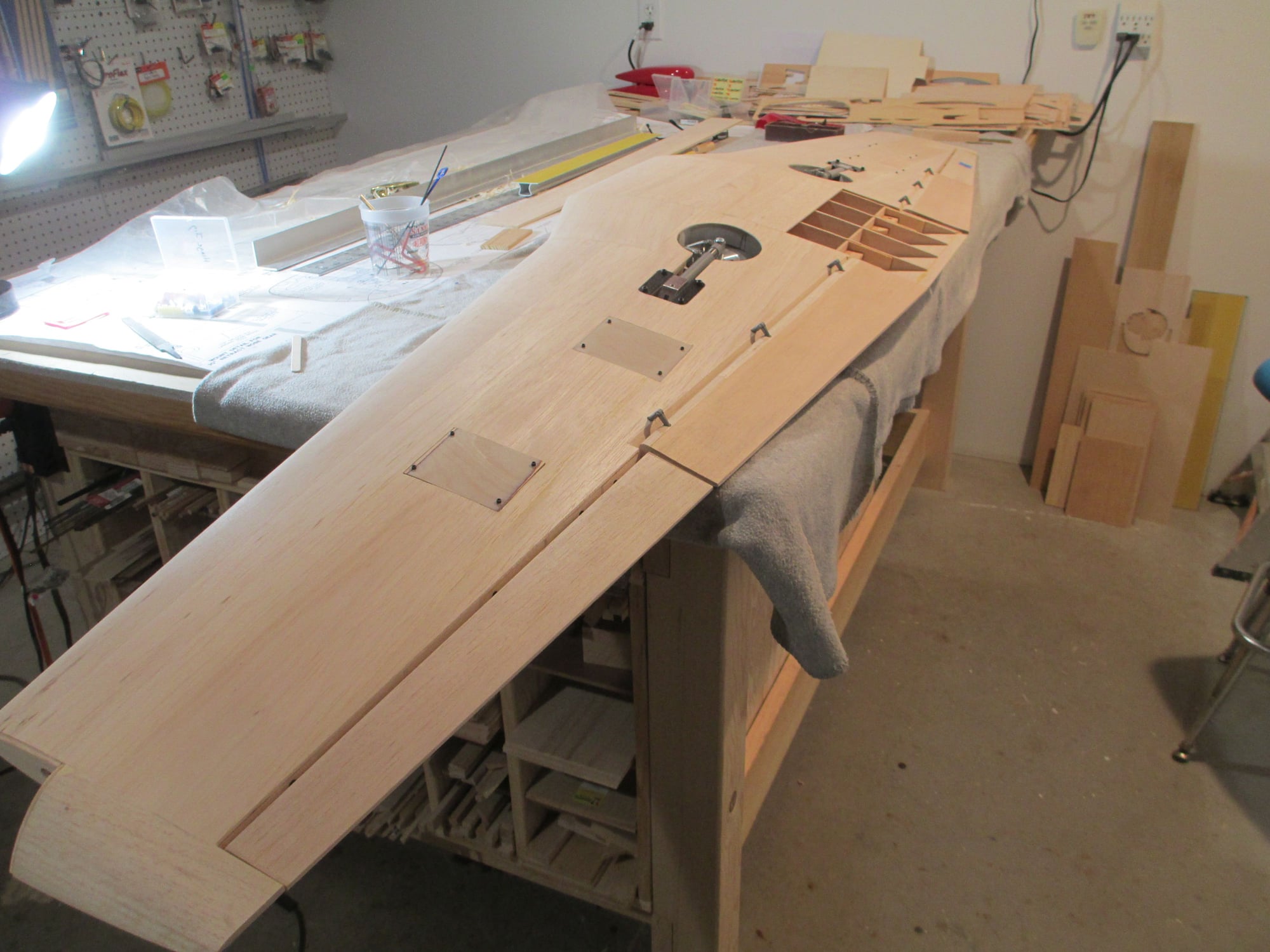
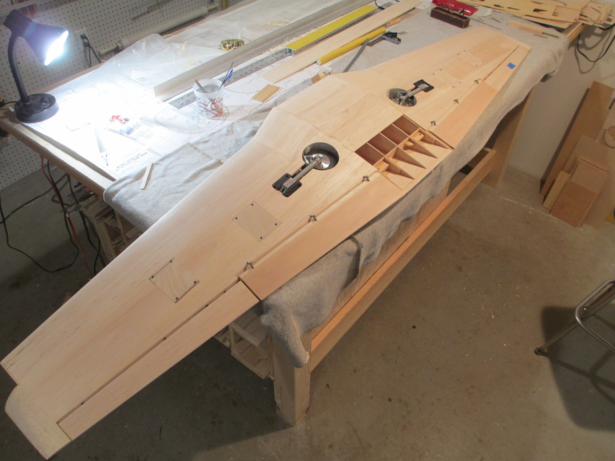
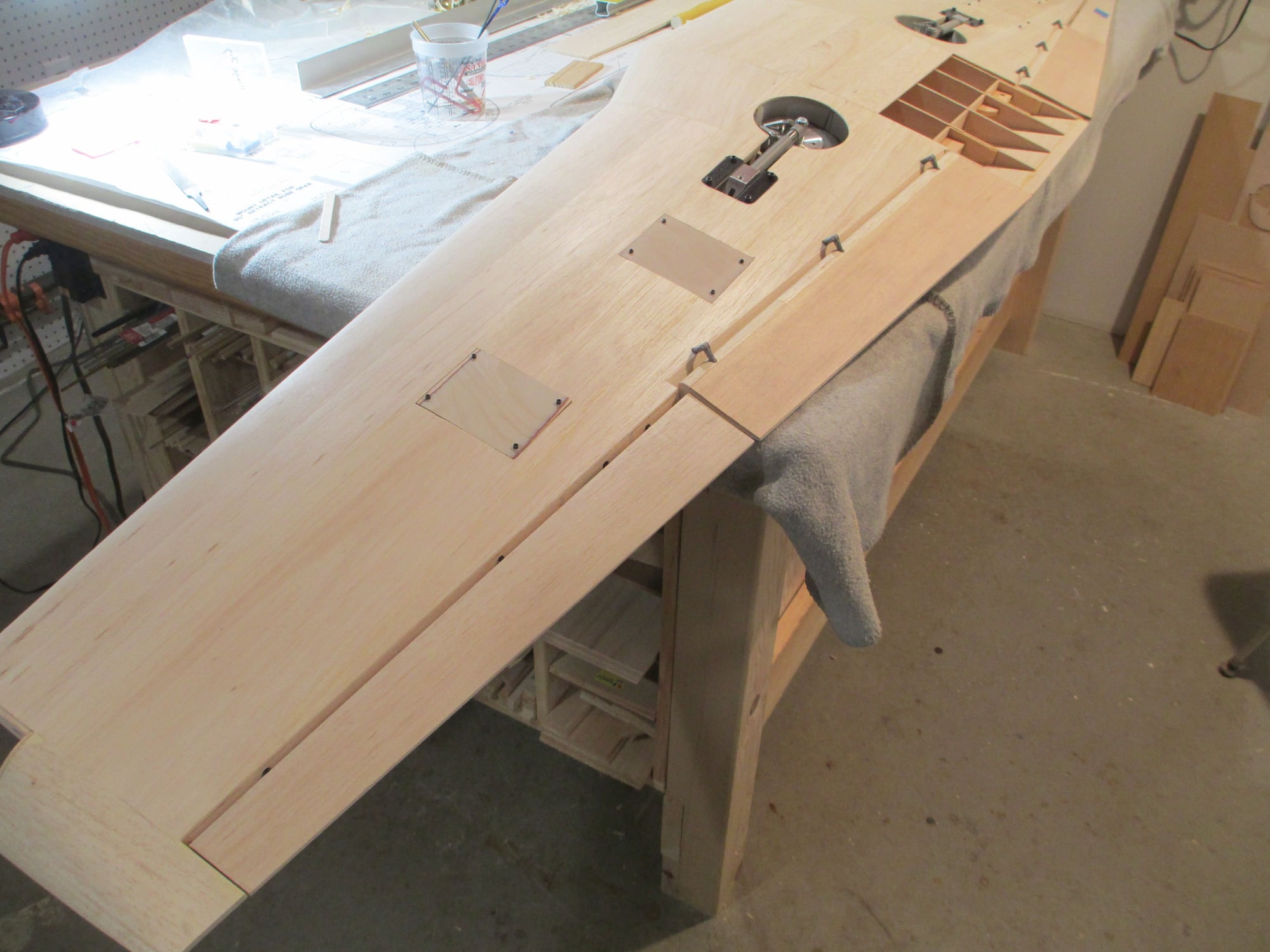
The left side of the wing is completed with the exception of some minor adjustments and finish sanding. I'm so excited as the bottom view of the wing has no visible linkages. Mission accomplished!!!
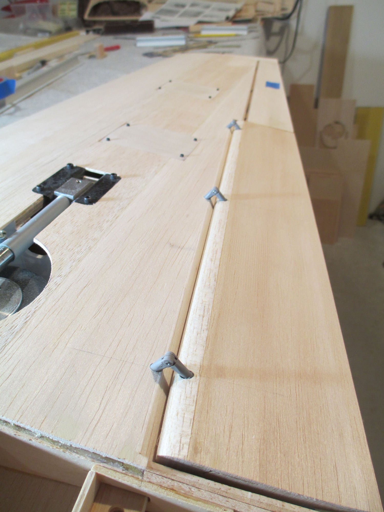
Using the drilling jigs made easy work keeping the holes straight and on point.
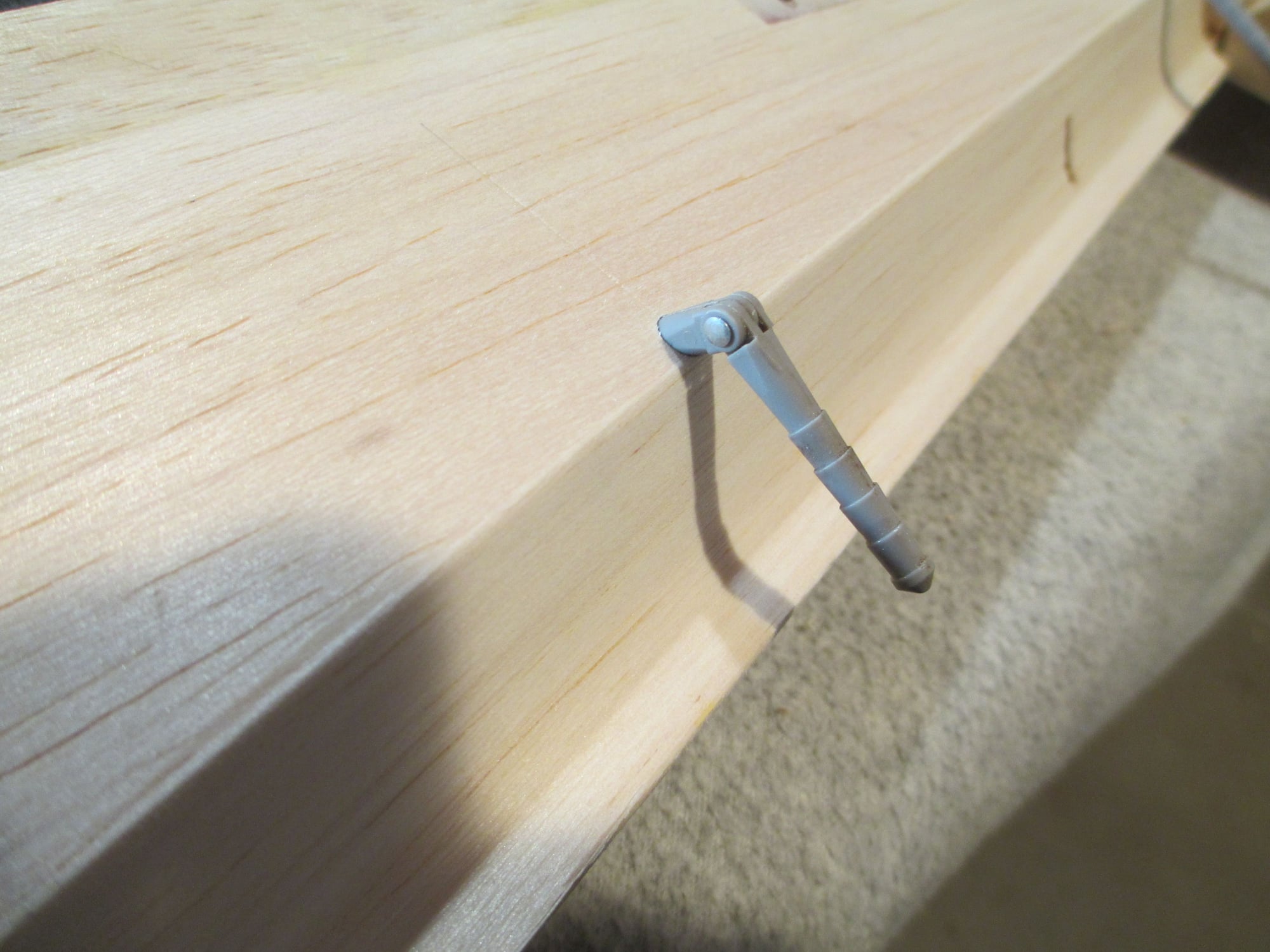
The gaps between the wing's trailing edge and the leading edges of the aileron and flaps are all good.
Flaps move without any binding.
 10-30-2019, 12:16 AM
#391
Thread Starter
10-31-2019, 01:18 PM
#392
Thread Starter
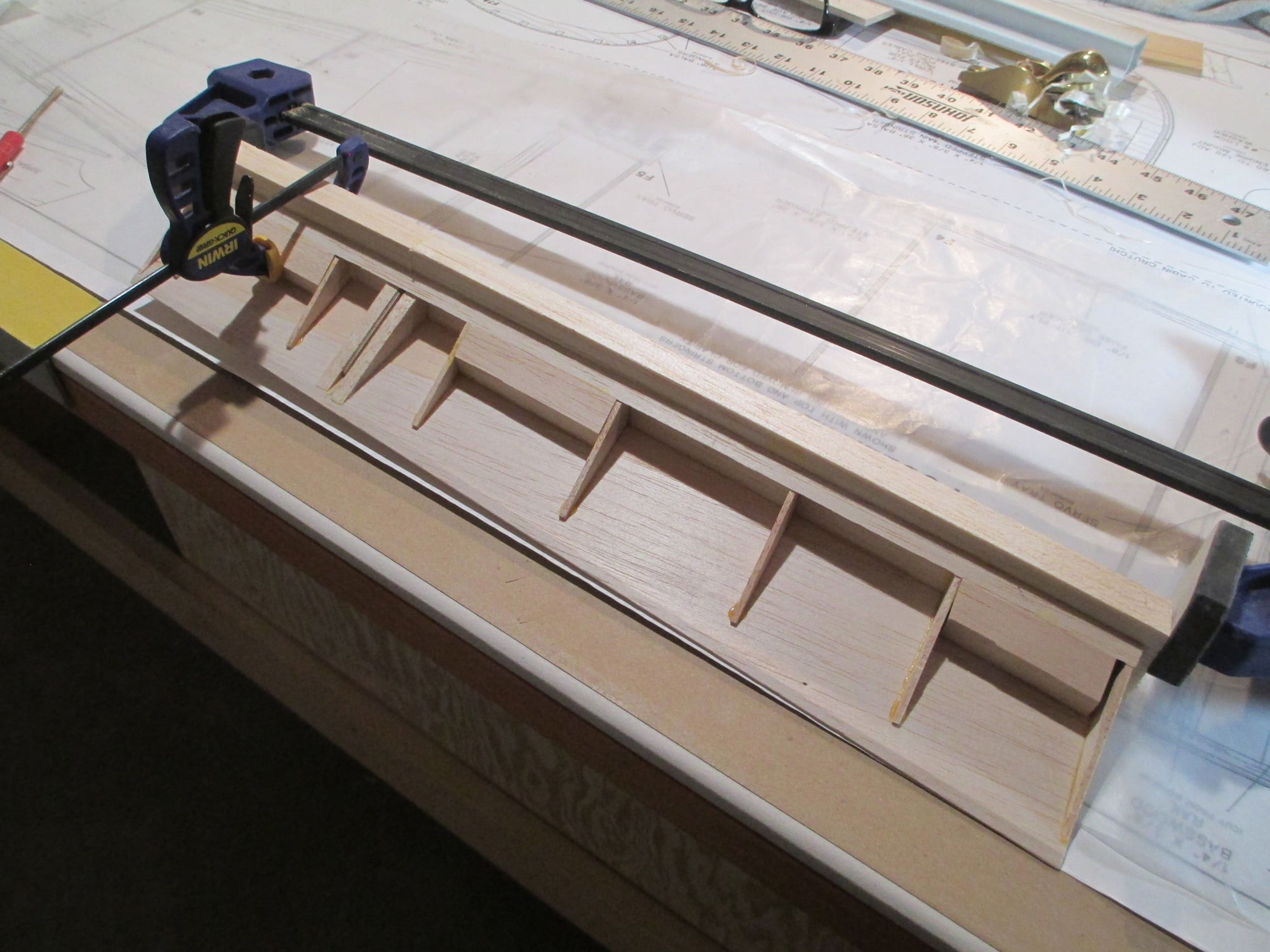
Work continues on the right flap. As soon as the glue sets, I'll be able to shape its leading edge as I had done to the other side. Note that the location of the horn is different as compared to the left side.
Last edited by VincentJ; 11-01-2019 at 04:55 AM.
11-04-2019, 04:09 PM
#393
Thread Starter
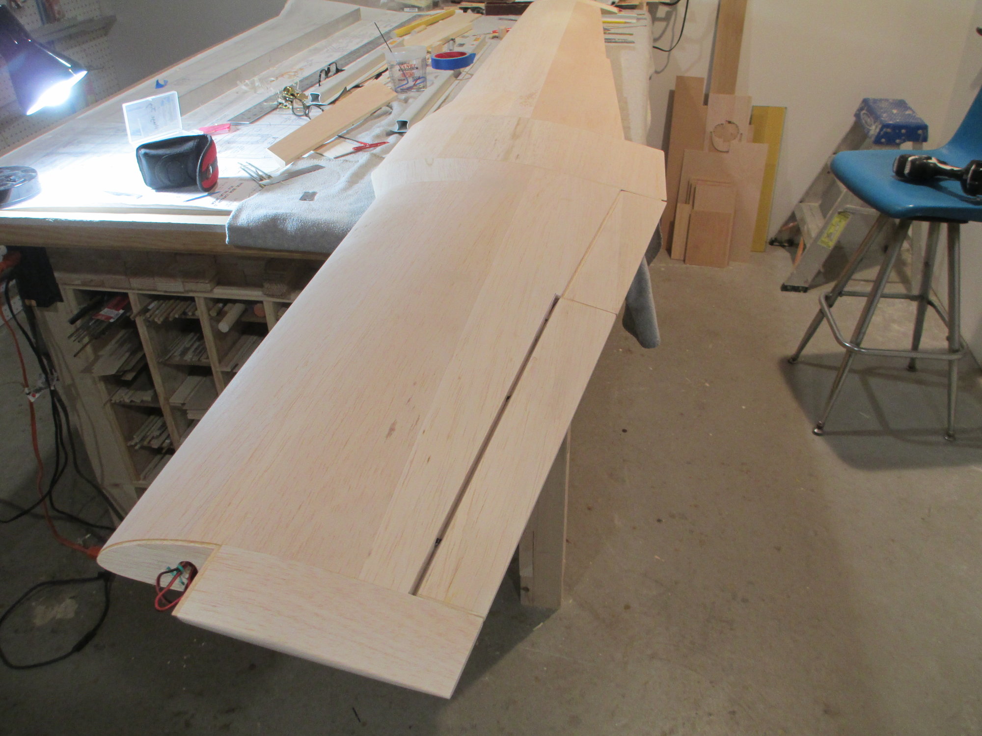
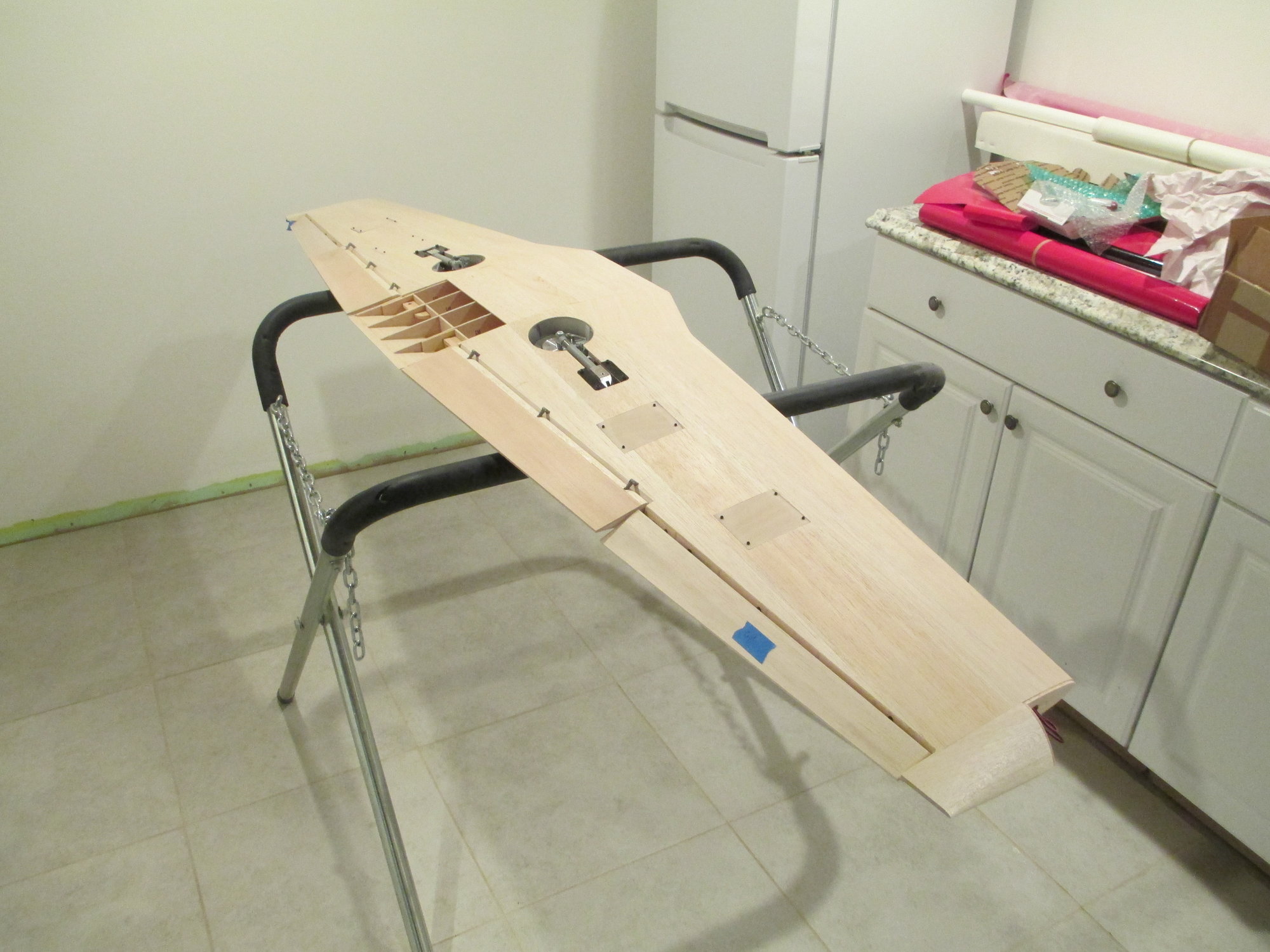
The wing is by no means done, but I have completed installing the ailerons and flaps. Alleluia! With enough of the wing completed, I can start the construction of the fuselage.
11-07-2019, 04:12 PM
#396
Thread Starter
Construction of the fuselage began by removing the wing from my build table to make some room!
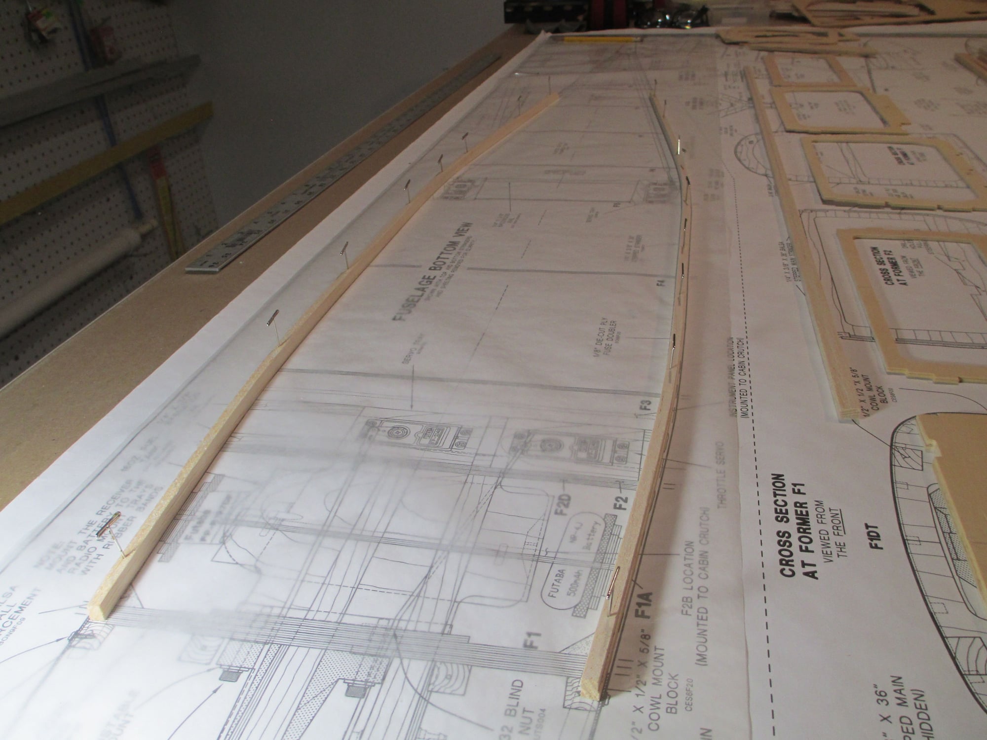
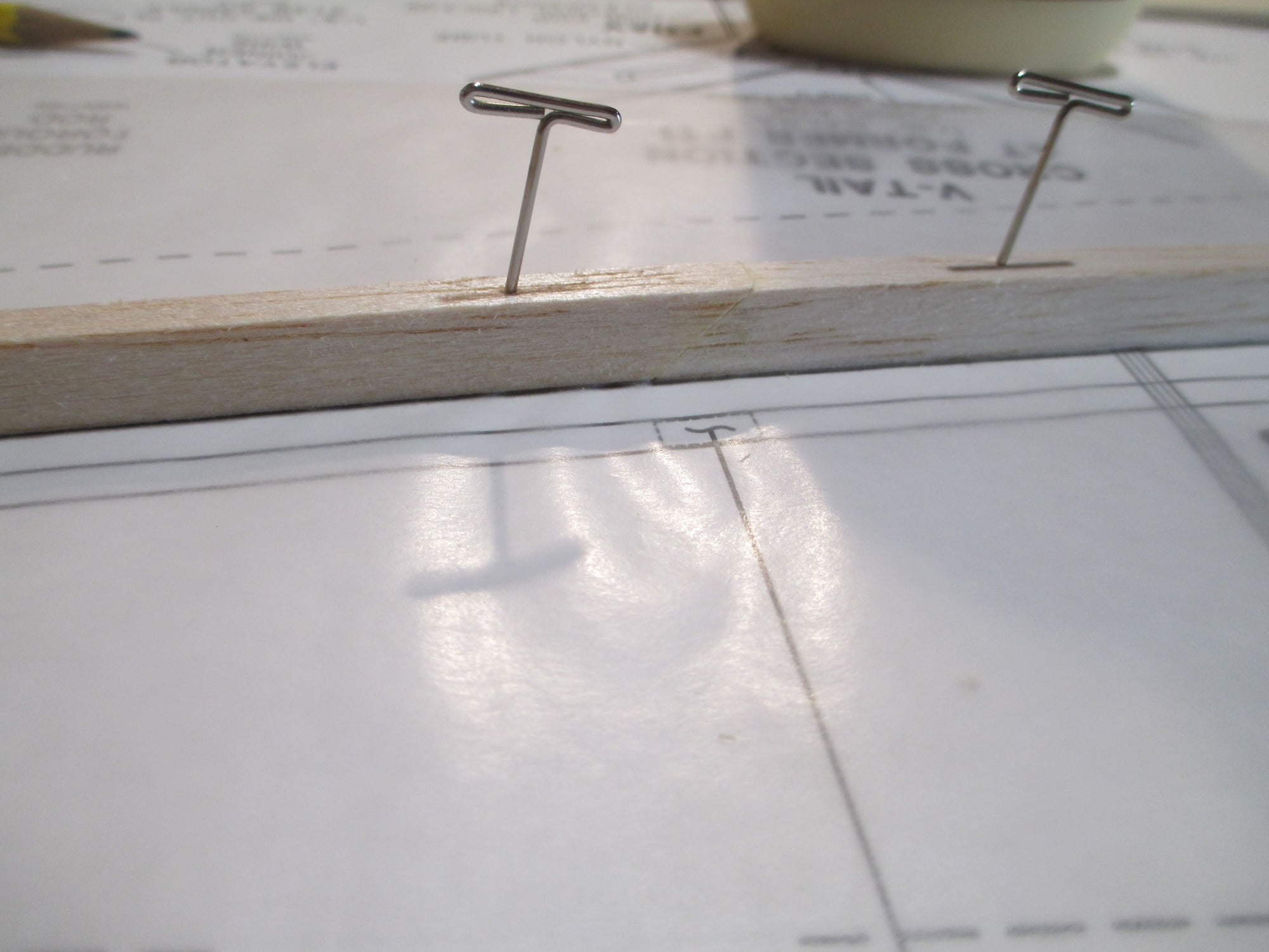
Two 1/4" x 3/8" x 36" stepped balsa side stringers were pinned to plan after each aft end was beveled to a 45 degree angle. This will allow another stringer to be spliced to the first increasing its overall length.
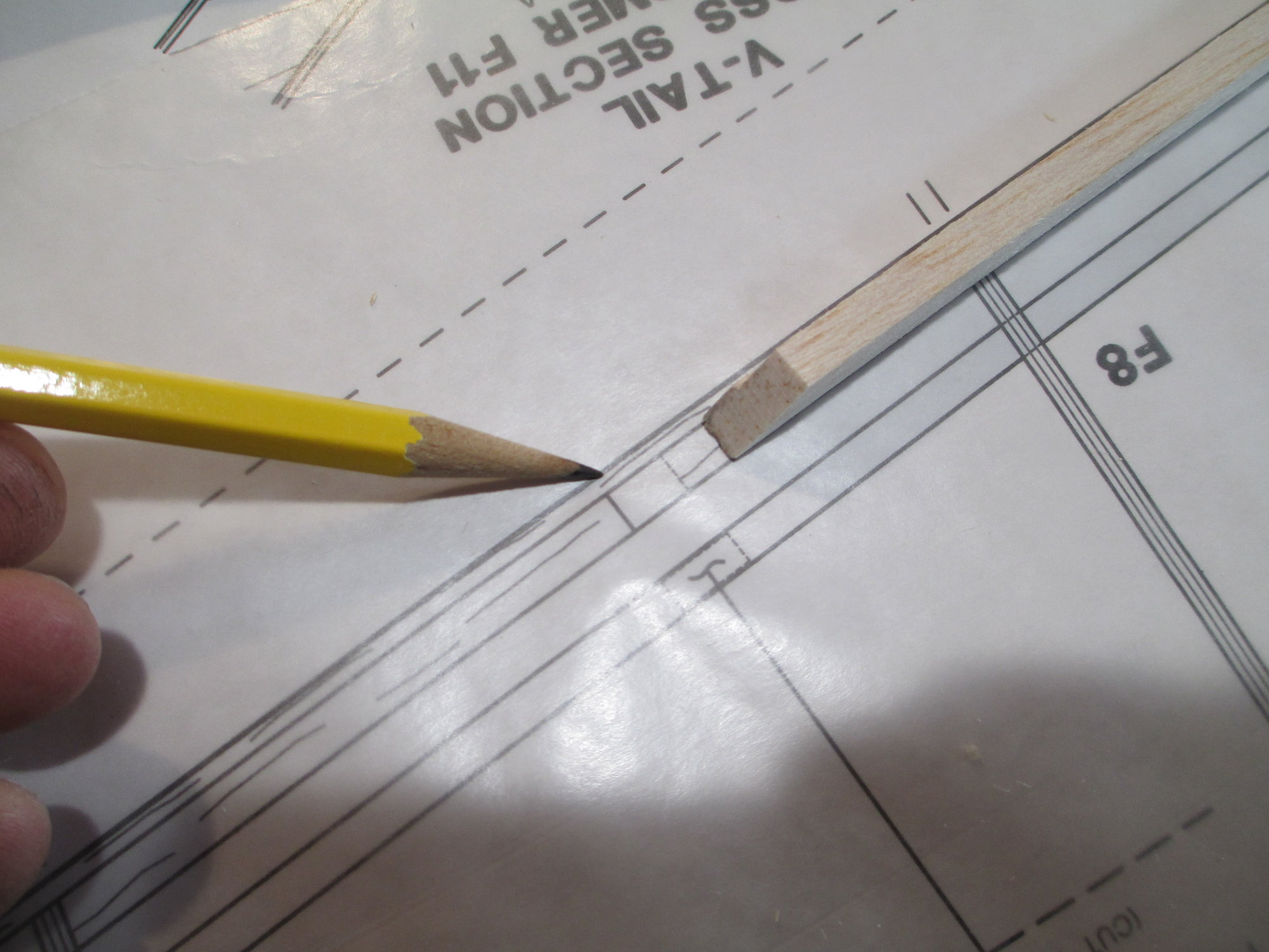
The plans show where the splice will be.
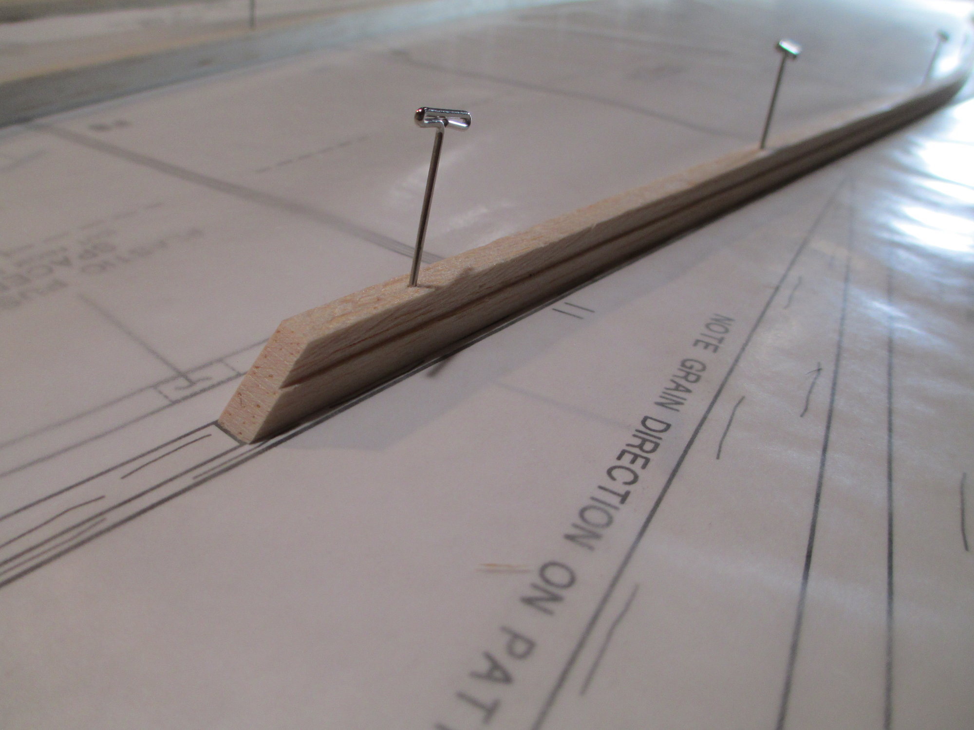
The side stringer is directly over the splice mark and pinned to the build table. Note that the step of each side stringer is facing towards the outside of the fuselage.
A second stringer is also beveled and glued to the beveled edge of the first, making the overall length correct. If you're wondering why the two side stringers are beveled rather than using a straight cut is because by beveling each end, you increase the surface area between the two stringers allowing more of a glue area making a stronger splice...
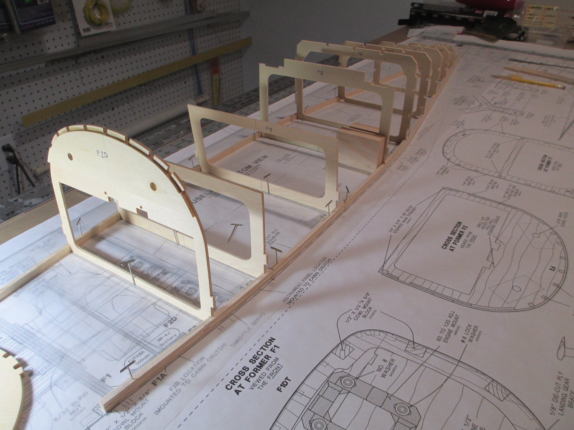
Each former from F1 through F11 is positioned between the two side stringers. They are not glued into place at this time as I want to check the fit. In fact, after the formers were positioned with their center lines on mark with the plans, I removed the "T" pins holding the side stringers to the board and snugged them up to the sides of each former. The pins were then put back into place. It is not uncommon for their to be a discrepancy between the printed plans and the actual size of the formers.
I made sure that the center line of each former lined up exactly with the plans center lines.
Last edited by VincentJ; 11-08-2019 at 05:15 AM.
11-08-2019, 04:06 AM
#398
Thread Starter
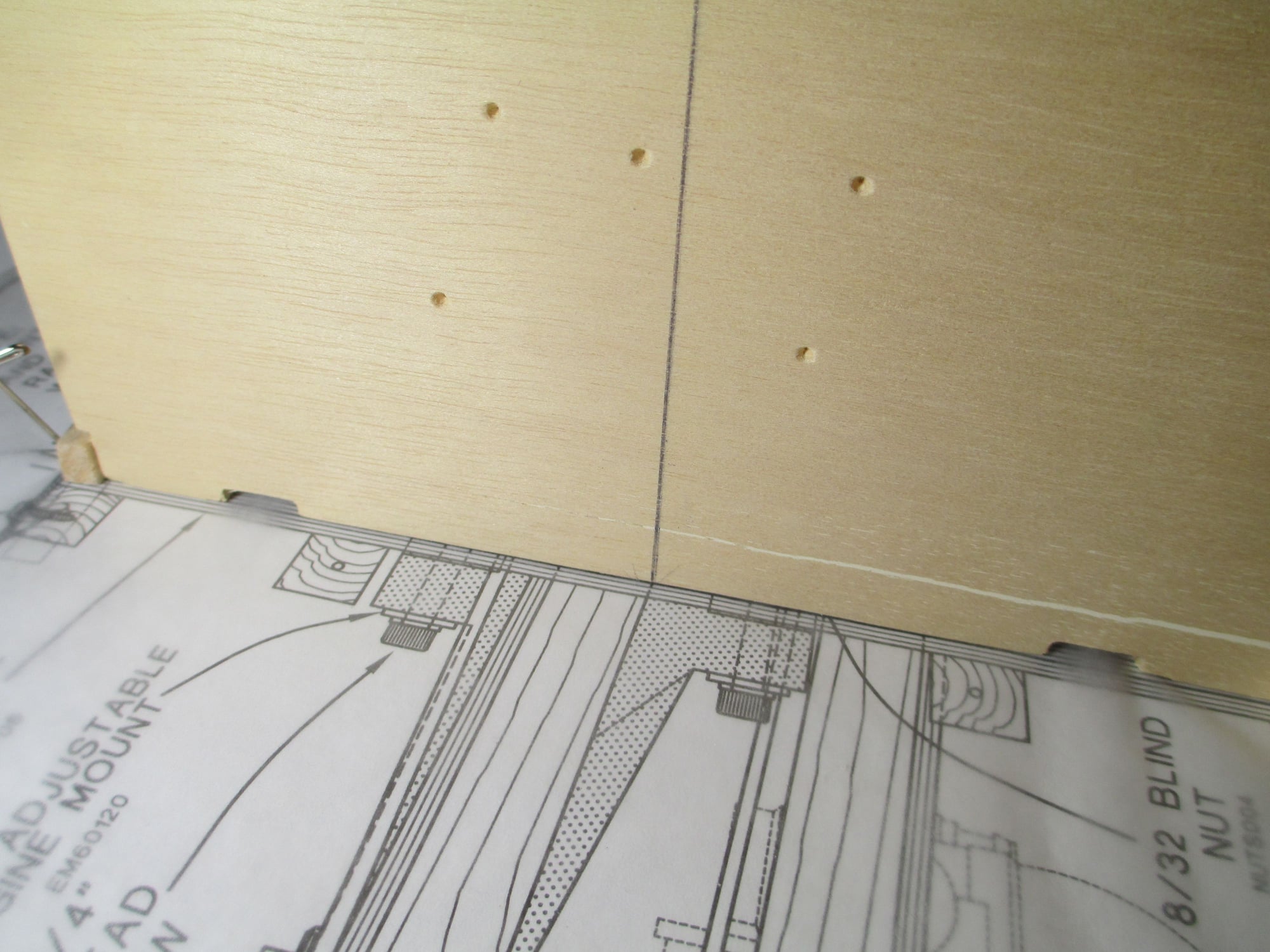
Not at this time Mike. The indents that you see in the former are for the engine/engine mount set-up recommended. Since I am installing a gas engine, those marks mean nothing to me. Once I determine where the holes need to be drilled, I will remove the former and use my drill press to ensure that each hole is perfectly straight.