FB 1/7th F15 scale build
 09-29-2015, 04:40 AM
#26


Short video of one of the inlets working. Almost done with the other side. Now I can get cranking on the rest of the build. I ordered all the parts I need to start on the hidden linkages. Will start that later this week I hope. Wont get anything done next week going on vacation.
https://www.facebook.com/kristopher....4552951615031/
https://www.facebook.com/kristopher....4552951615031/
 09-29-2015, 09:21 AM
#28
Thnx Braza!! Got any pics of your install yet? If anyone wants to post pics of thier install please do. Trying to get ideas. Think im going to put ECU batt and receiver batts all in the nose depending on CG and all air valves on right side of inlet and receiver and gyro on left side of inlet so I the servo wires are shorter and airlines shorter.
09-29-2015, 05:56 PM
#29
Thanks for the invitation Gunradd.
Here are some pics of my install.
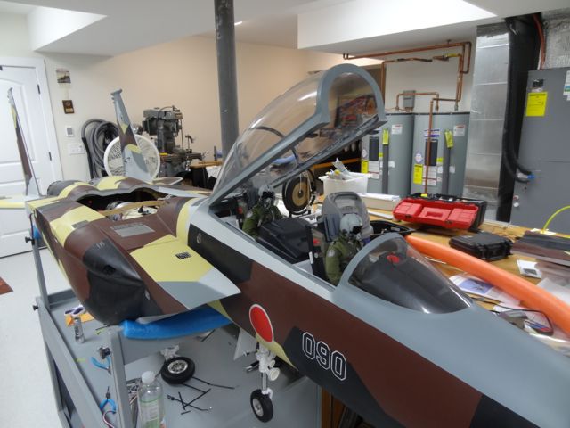
The paint scheme is from a Japanese aggressor F-15D (yes, a slight sin, technically this is a fantasy scheme to put a D paint job on an E aircraft). I asked FB to leave off the clear coat so I could add some graphics and I'll add the matte clear after that. I'll probably maiden it and fly it some as it sits.
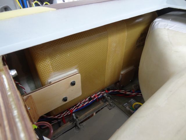
I elected to cut through the inlet ducts to take the Y-shaped part out during install. As you can see, I've got it reattached with white duct tape and am debating if I need something more robust. I'd actually prefer not to follow my original plan and glass the seams back permanently. It would be a wonderful upgrade to the kit if FB would consider putting a slip joint in the inlets at about the point where I cut them - for initial install and maintenance. I also removed the covers over the main gear wheel wells as I found it impossible to rig the gear doors and install the tanks with them in place. I currently do not plan to replace them. I did leave the nose gear well cover in place.
Like many builders I elected to cut off the nose cone and make it removable, there are three steel pins that position it at matching bulkheads I installed on either side of the cut. A single knurled screw holds it fast, accessible through a small flip-down at the nose that secures with a rare-earth magnet.
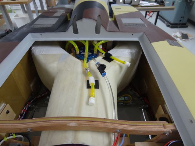
I did my best to put some weight in the nose (main batteries, etc), and to make all the startup/flightline stuff accessible without opening the main hatch. Currently I have the fuel fill, smoke fill and smoke system switch in the main hatch as that is something I generally do back in the pits, not at the flight line. I went a little crazy with 6 charge ports only 4 in use at this time (2x main RX batt, lighting system batt shared by lighting and AB ring, smoke battery). In the end I was a few mm nose heavy (!) compared to the 235mm suggested point so I placed the ECU battery back in the main hatch.
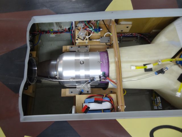
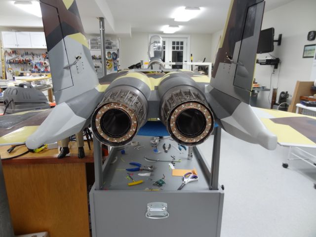
I used the Jet Central gear and canopy sequencer (which really is quite convenient) and JetTronics valves for the air functions. Robart restrictors on the air brake, canopy and all doors to keep them from slamming. I am not using the stock fuel tanks (they are fine but I wanted to set up differently). I had a set of larger "side" tanks made by Gary Mueller (Jet Tech), and his Reaction 54-size tank in the center position for smoke. The two side tanks feed the extra large Tom Cook/JMP Vertical Air Trap. The JMP trap is mounted in a plywood holder that is glassed to the fuse floor. It gives me about 230 oz of fuel and 72 oz of smoke. I have the PowerBox smoke pump and one large-size (3/16") Tam smoke injector .. this is a great combo I have used before. I did not order the plane with a pipe so the bifurcated pipe was done by Tam for the P200.
Power distribution and dual RX selection is via a Robbe PSS2018 power box with 2xR7008 Receivers. CB associates JetCat ECU telemetry unit and pitot/static airspeed sensor, all A123 batteries.
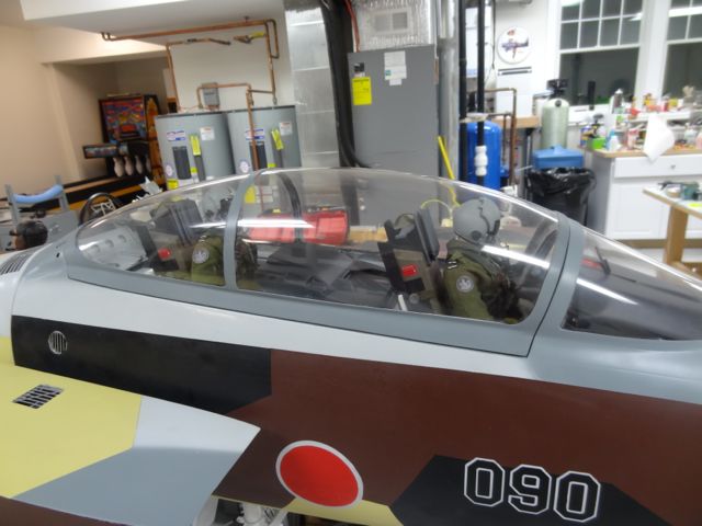
Pilots are from Tailored Pilots in the UK. The cockpits that come with the plane are quite nice (my son, an F-15E pilot, and his WSO colleagues declared them "pretty legit!" .. they also advised me that for the full "scale effect" the position light on the tail should be burned out :-) ). The pilot sitting position was not quite right - it was hard to get the pilots to sit low enough (they are a still bit too high), I had to cut the plastic seat "cushion" out and put the pilot torso on the floor and remove the molded legs and stuff the flight suit with cotton . None of that is visible with the pilots installed. I think they look great in the plane now.
To get the canopy to work reliably, I had to move the air cylinder bottom mounting point back about 2" to get better mechanical advantage at initial opening - no big deal and it really helped. I saw a very clever canopy lock mechanism on a friend's SM F-14 with wedge-shaped plungers driven by small air cylinders .. the small wedges are driven into a BVM canopy hook that faces forward so that as the air cylinders push toward lock the wedge engages with the slanted edge of the hook and pulls the canopy down strongly. It locks very tightly and releases easily. Nice. And easy to program with the JC sequencer.
Lighting system from Details 4 Scale, as well as the AB rings.
Dave McQ


Here are some pics of my install.
The paint scheme is from a Japanese aggressor F-15D (yes, a slight sin, technically this is a fantasy scheme to put a D paint job on an E aircraft). I asked FB to leave off the clear coat so I could add some graphics and I'll add the matte clear after that. I'll probably maiden it and fly it some as it sits.
I elected to cut through the inlet ducts to take the Y-shaped part out during install. As you can see, I've got it reattached with white duct tape and am debating if I need something more robust. I'd actually prefer not to follow my original plan and glass the seams back permanently. It would be a wonderful upgrade to the kit if FB would consider putting a slip joint in the inlets at about the point where I cut them - for initial install and maintenance. I also removed the covers over the main gear wheel wells as I found it impossible to rig the gear doors and install the tanks with them in place. I currently do not plan to replace them. I did leave the nose gear well cover in place.
Like many builders I elected to cut off the nose cone and make it removable, there are three steel pins that position it at matching bulkheads I installed on either side of the cut. A single knurled screw holds it fast, accessible through a small flip-down at the nose that secures with a rare-earth magnet.
I did my best to put some weight in the nose (main batteries, etc), and to make all the startup/flightline stuff accessible without opening the main hatch. Currently I have the fuel fill, smoke fill and smoke system switch in the main hatch as that is something I generally do back in the pits, not at the flight line. I went a little crazy with 6 charge ports only 4 in use at this time (2x main RX batt, lighting system batt shared by lighting and AB ring, smoke battery). In the end I was a few mm nose heavy (!) compared to the 235mm suggested point so I placed the ECU battery back in the main hatch.
I used the Jet Central gear and canopy sequencer (which really is quite convenient) and JetTronics valves for the air functions. Robart restrictors on the air brake, canopy and all doors to keep them from slamming. I am not using the stock fuel tanks (they are fine but I wanted to set up differently). I had a set of larger "side" tanks made by Gary Mueller (Jet Tech), and his Reaction 54-size tank in the center position for smoke. The two side tanks feed the extra large Tom Cook/JMP Vertical Air Trap. The JMP trap is mounted in a plywood holder that is glassed to the fuse floor. It gives me about 230 oz of fuel and 72 oz of smoke. I have the PowerBox smoke pump and one large-size (3/16") Tam smoke injector .. this is a great combo I have used before. I did not order the plane with a pipe so the bifurcated pipe was done by Tam for the P200.
Power distribution and dual RX selection is via a Robbe PSS2018 power box with 2xR7008 Receivers. CB associates JetCat ECU telemetry unit and pitot/static airspeed sensor, all A123 batteries.
Pilots are from Tailored Pilots in the UK. The cockpits that come with the plane are quite nice (my son, an F-15E pilot, and his WSO colleagues declared them "pretty legit!" .. they also advised me that for the full "scale effect" the position light on the tail should be burned out :-) ). The pilot sitting position was not quite right - it was hard to get the pilots to sit low enough (they are a still bit too high), I had to cut the plastic seat "cushion" out and put the pilot torso on the floor and remove the molded legs and stuff the flight suit with cotton . None of that is visible with the pilots installed. I think they look great in the plane now.
To get the canopy to work reliably, I had to move the air cylinder bottom mounting point back about 2" to get better mechanical advantage at initial opening - no big deal and it really helped. I saw a very clever canopy lock mechanism on a friend's SM F-14 with wedge-shaped plungers driven by small air cylinders .. the small wedges are driven into a BVM canopy hook that faces forward so that as the air cylinders push toward lock the wedge engages with the slanted edge of the hook and pulls the canopy down strongly. It locks very tightly and releases easily. Nice. And easy to program with the JC sequencer.
Lighting system from Details 4 Scale, as well as the AB rings.
Dave McQ
Last edited by ww2birds; 09-29-2015 at 06:11 PM.
09-30-2015, 02:29 AM
#30

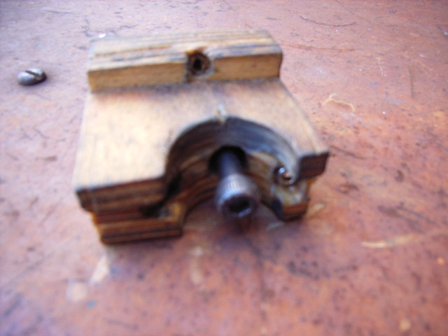
I had no end of trouble with the main gear on this model,for the designers to expect the tracking to be controlled by that lever fixedto a silly little square was ridiculous. They did introduce a mod in the formof a bar fixed to the side frame but that too was ridiculous (don�t know ifyours has this little modification)?
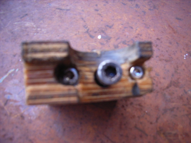
My solution was to introduce a tailored block bolted to thecross beam for the leg to fit into, the centre bolt fixes the block to the beamwhilst the two outer bolts are for tracking adjustment. I also converted thegear and doors to hydraulic to get over the problem of the gear and doorsrefusing to work properly in the considerable air stream after take off.
https://youtu.be/dIfvzfLCNQQ?list=FL...DJcUNuf7YKFO-A
09-30-2015, 05:22 AM
#32
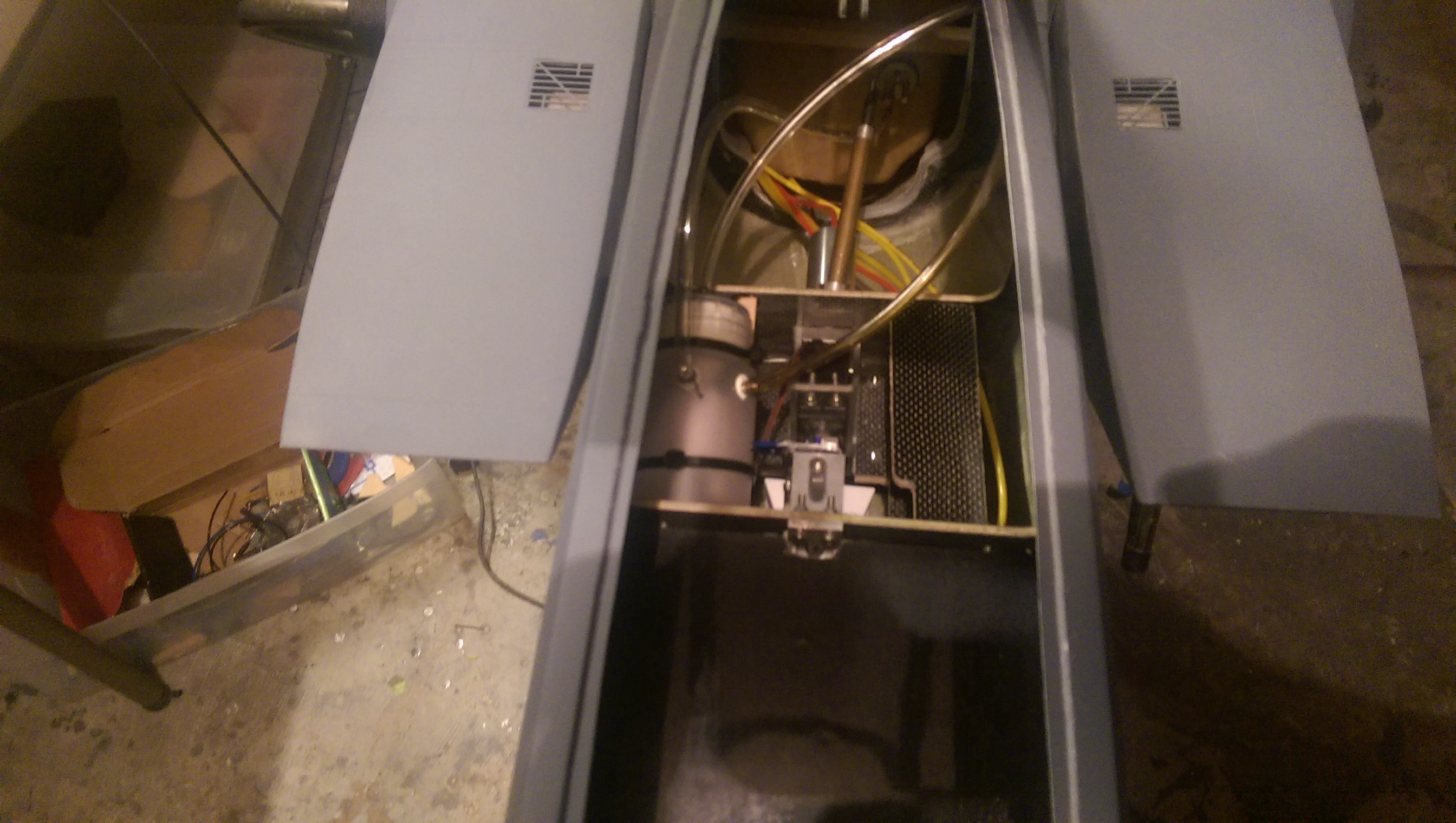
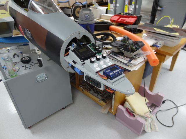
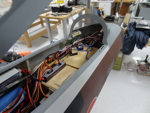
Building equipment boards today.
I am wanting to install the receiver and gyro on the left side and air system stuff on right side. Placing the receiver here cuts off about 2 feet of wire per channel. I am thinking ill use 16 channels on this bird.
Last edited by gunradd; 09-30-2015 at 05:27 AM.
09-30-2015, 07:58 AM
#34
From the pics I posted the one with sequence number 05 (cockpit area looking forward) has it .. you might be able to see if you zoom in. Tonight I can take a better pic. It's really simple .. even simpler than the SM F-14 one that inspired it. Honestly I was surprised at how well it worked.
I thought about having the nose cone open by swinging sideways like the full-scale but that would not have allowed me to do a very big equipment board .. but since I know now how the CG came out .. it might actually be workable if someone wants to try it (see here: http://www.dailyairforce.com/162/boe...from-raytheon/)
I continue to fret about the rotating gear on grass where I will mostly fly it. The GJC guys are helping me see if I can get a set of straight (non-rotating) main gear mechanics. I was very interested to see Mick's mod .. that's very clever. My gear have an extra metal part that bolts on behind the strut at the base of the retract frame and while it provides some extra support front-to-back when the gear is down, it does not stabilize the gear leg in rotation which is what concerns me. The FB design is nice but I am really thinking its a lot to ask of it to handle the abuse of a grass field.
Dave
09-30-2015, 04:29 PM
#35
Here are some better pics of the canopy lock mechanism. I added two of the standard BVM canopy hooks to the canopy frame and made slots in the fuse to receive them.
The wedges are made from maple and the small air cylinders came from Dreamworks. I tapped the maple blocks and the threads on the cylinders screw into them. The air cylinders are very nicely made and have air restrictors built into the tubing connectors which is perfect for this application.
First pic is open position, second locked, third and fourth to see the wedge better, fifth is the canopy hooks.
Hope this helps.
Dave
Last edited by ww2birds; 09-30-2015 at 04:41 PM.
09-30-2015, 08:38 PM
#36

I really need to get mine out of storage and finish it. This thread is good motivation. I was thinking of doing the nose cone to open sideways and make a radar to put in it.
Great work everyone
Mick i know i have seen your hydraulic set up can you share the link again
David
Great work everyone
Mick i know i have seen your hydraulic set up can you share the link again
David
10-01-2015, 02:56 AM
#37
Dave thanks for the pics! Very simple and effective. I think I will copy you on that  .
.
David get that F15 out and start cranking on it!!
Last night I got most of the air system completed. Its going very fast. If I was not doing all the scale stuff you could have this plane from box to the air in less then a month just working evenings on it.
.David get that F15 out and start cranking on it!!
Last night I got most of the air system completed. Its going very fast. If I was not doing all the scale stuff you could have this plane from box to the air in less then a month just working evenings on it.
10-01-2015, 05:15 PM
#39
One step forward two steps back....
Left main gear cylinder has an internal leak real bad. Like i has no oring on the piston. Also have an airpower dual action valve not working correctly its not letting air in one of the directions. Swapped it out with another one and got that working.
Left main gear cylinder has an internal leak real bad. Like i has no oring on the piston. Also have an airpower dual action valve not working correctly its not letting air in one of the directions. Swapped it out with another one and got that working.
10-02-2015, 11:49 AM
#43
From the start I knew I had to get a Tam pipe as specially when I drop the K300 in this plane. Until the 300 is ready I am going to use a K210 and was hoping the stock pipe would last temporarily while i get some stick time in and save up for a tam pipe. Well the stock pipe is a total joke and far from airworthy. Also its not even the correct shape. The rear of it would rub on the inside of the exhaust cones if used. They should not have even bothered to make the thing. The seams on it are hanging off the sides and rough poorly done seams indie the pipe. Total joke.
So needless to say I am going to have to order a Tam pipe before I can fly this plane. Cant wait to install the new K300!!
Also orderd burner lights,nav lights and landing lights. Will try and install the landing lights inside the housings on the nose gear and make some lenses.
So needless to say I am going to have to order a Tam pipe before I can fly this plane. Cant wait to install the new K300!!
Also orderd burner lights,nav lights and landing lights. Will try and install the landing lights inside the housings on the nose gear and make some lenses.
10-02-2015, 11:51 AM
#44
Also anyone flying one of these what did you do with the airbrake? It does not go high enough to be scale. Did the stock setup work ok? I have a large hole drilled on mine with a tiny screw going through it so lots of play on mine and I will need to fix where the actuator attaches to the hatch.
10-04-2015, 01:34 AM
#46

My Feedback: (3)
I have an old generation FB 1/7 F-15, could anyone advise if major changes have been made on the latest version produced, it seems that for LG besides the small mod of the main gear nothing has changed much.
Mainly worried about the plane itself, in terms of strength, lighter construction maybe and general modifications for elevator mechanism etc...
Thanks in advance,
Rgds,
Mainly worried about the plane itself, in terms of strength, lighter construction maybe and general modifications for elevator mechanism etc...
Thanks in advance,
Rgds,
10-04-2015, 11:55 AM
#47
I have an old generation FB 1/7 F-15, could anyone advise if major changes have been made on the latest version produced, it seems that for LG besides the small mod of the main gear nothing has changed much.
Mainly worried about the plane itself, in terms of strength, lighter construction maybe and general modifications for elevator mechanism etc...
Thanks in advance,
Rgds,
Mainly worried about the plane itself, in terms of strength, lighter construction maybe and general modifications for elevator mechanism etc...
Thanks in advance,
Rgds,
 10-10-2015, 04:19 AM
#50
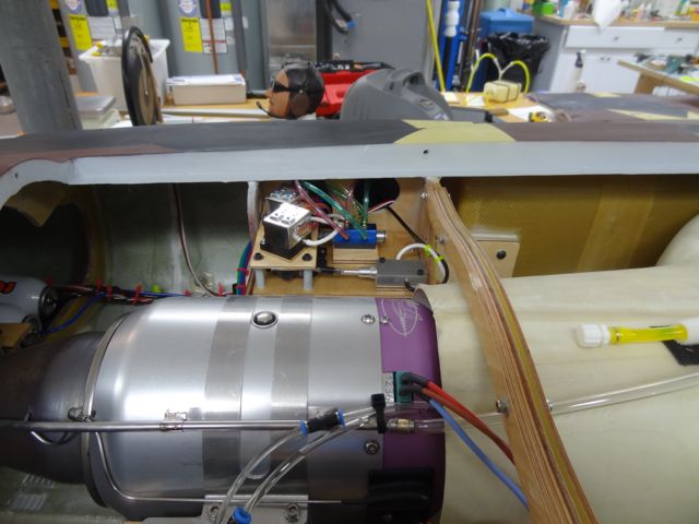
Also decided to install the Kingtech UAT just in front of the main tank. This will keep the suction side of the fuel system short. The pump will go next to it on the other side. In general its better to extend the pressure side if needed and keep the suction side short.