


1/7 Scale Blackburn Buccaneer All Composite Scratch Build


 10-19-2019, 12:22 PM
#328

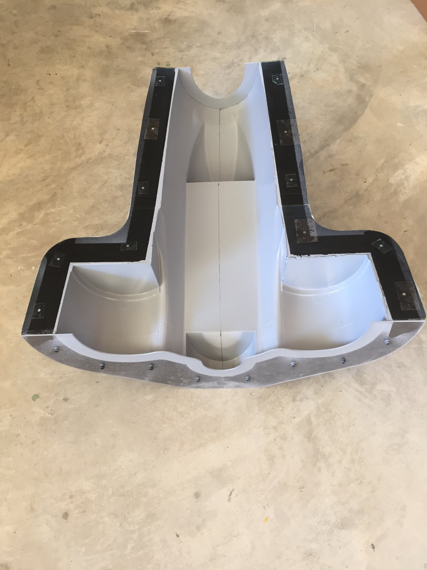
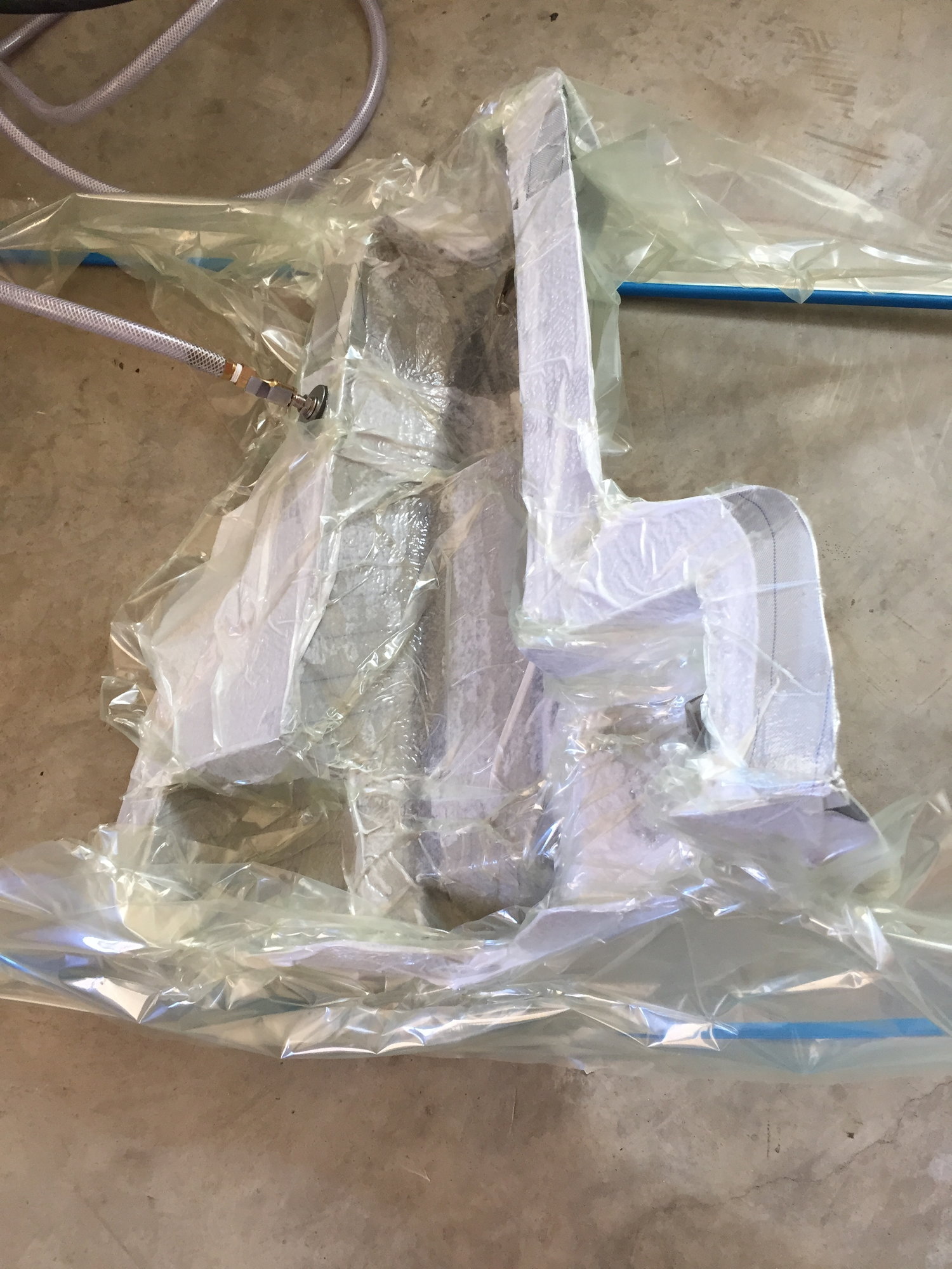
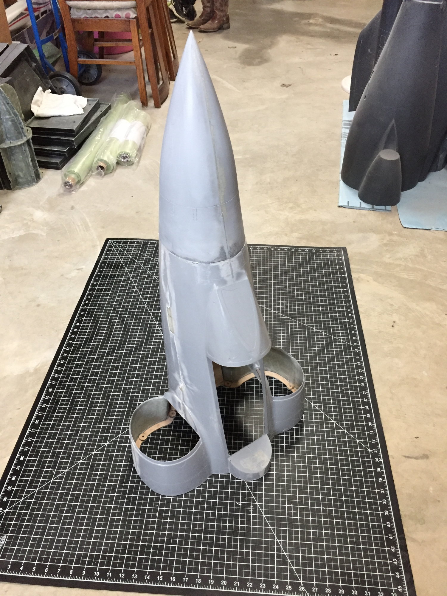
The forward fuselage is starting to take shape. This has probably been the biggest and most complex part that I've molded so far. It took a few hours on each half to spray the primer and lay up the glass/ carbon. I struggled with holding a vacuum on the first part, so that half was effectively done without vacuum bagging, but I got a good vacuum with the second half. Both halves looked like they came out well, although I haven't pulled them out of the molds. Fingers crossed for when I join them together.
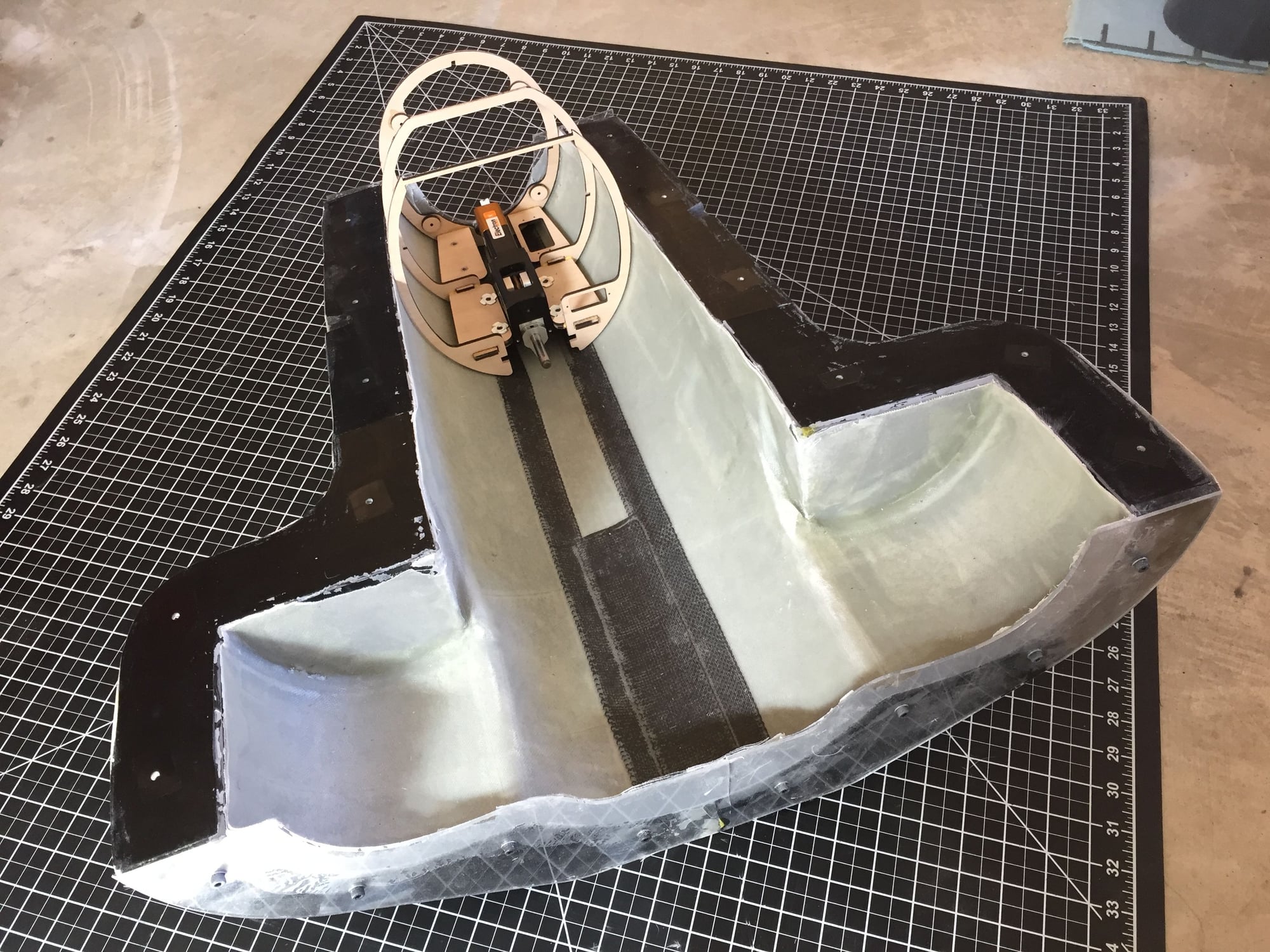
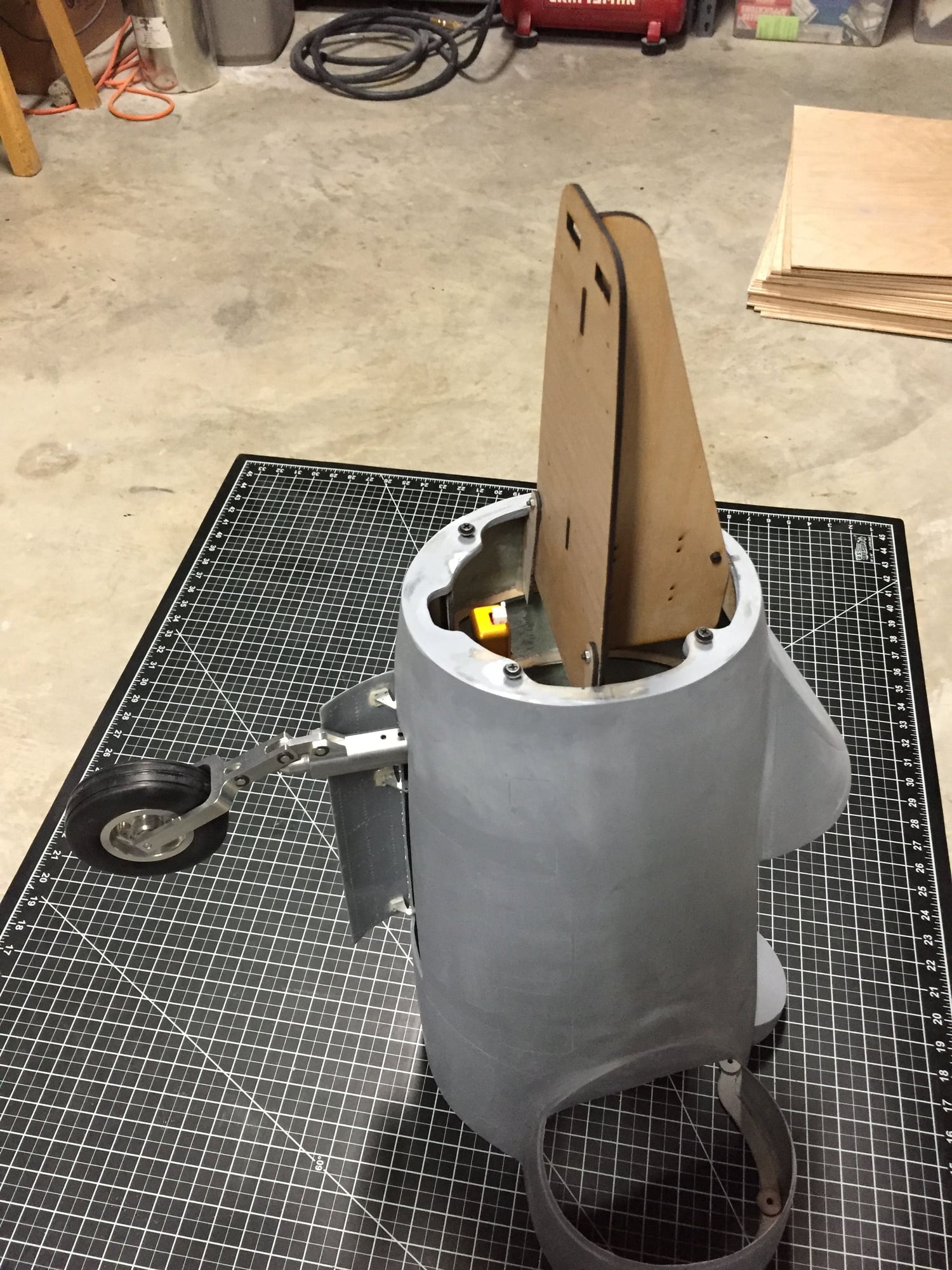
I have started to cut out and dry-fit the internal structure. Now just waiting on more custom plywood before I can progress much further. Nose wheel steering and nose gear door servo mounts integrated into the structure, along with a ballast mounting tray.
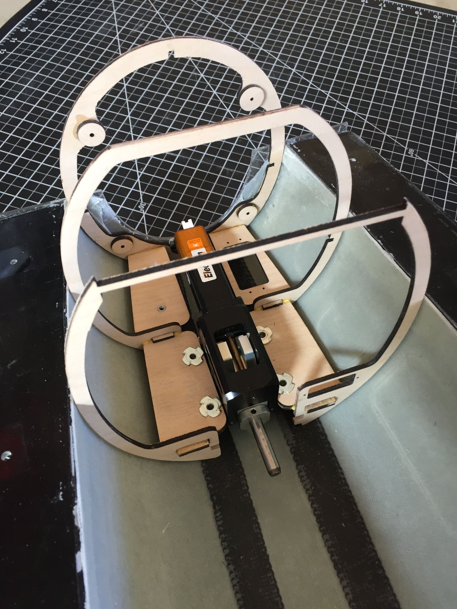
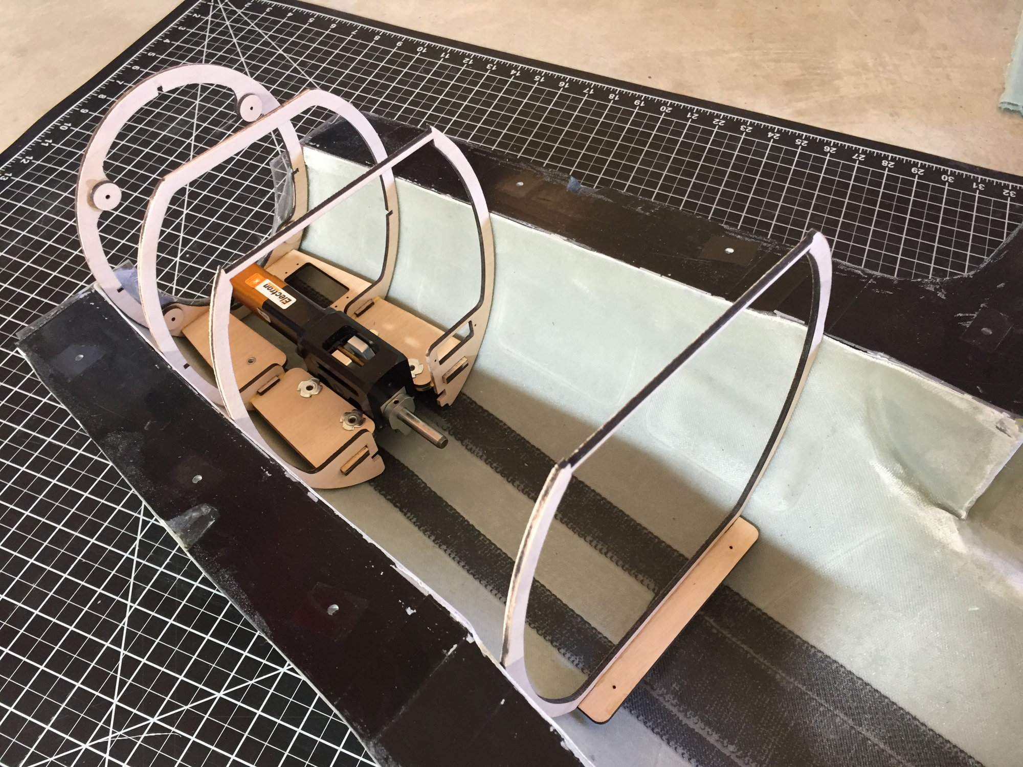
Paul
I have started to cut out and dry-fit the internal structure. Now just waiting on more custom plywood before I can progress much further. Nose wheel steering and nose gear door servo mounts integrated into the structure, along with a ballast mounting tray.
Paul
Last edited by JSF-TC; 10-19-2019 at 12:30 PM.
 10-19-2019, 01:52 PM
#331
Dave's correct. Just plywood.
However, it is custom made, MIL-spec, 5-ply all birch plywood with melamine glue to make it laser cutter compatible.Works out at about $4 per sq.ft, which is way cheaper than hobby prices.
Home - Aircraft Plywood Mfg.
Paul
However, it is custom made, MIL-spec, 5-ply all birch plywood with melamine glue to make it laser cutter compatible.Works out at about $4 per sq.ft, which is way cheaper than hobby prices.
Home - Aircraft Plywood Mfg.
Paul
10-20-2019, 12:31 AM
#332
Wow the black burn fooled me into thinking it was a carbon fiber sandwich setup. Thanks Dave!
5-ply Birch is excellent. I have two sheets of 8'x2' sheet and they just like gold to me. Wonderful stuff. Pity we do not get that stuff in my location.
Thanks again.
Reuben
5-ply Birch is excellent. I have two sheets of 8'x2' sheet and they just like gold to me. Wonderful stuff. Pity we do not get that stuff in my location.
Thanks again.
Reuben
11-03-2019, 12:55 PM
#333
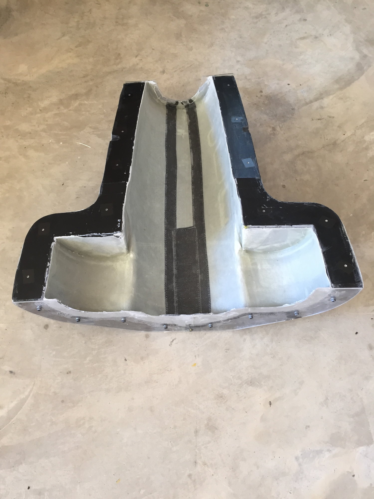
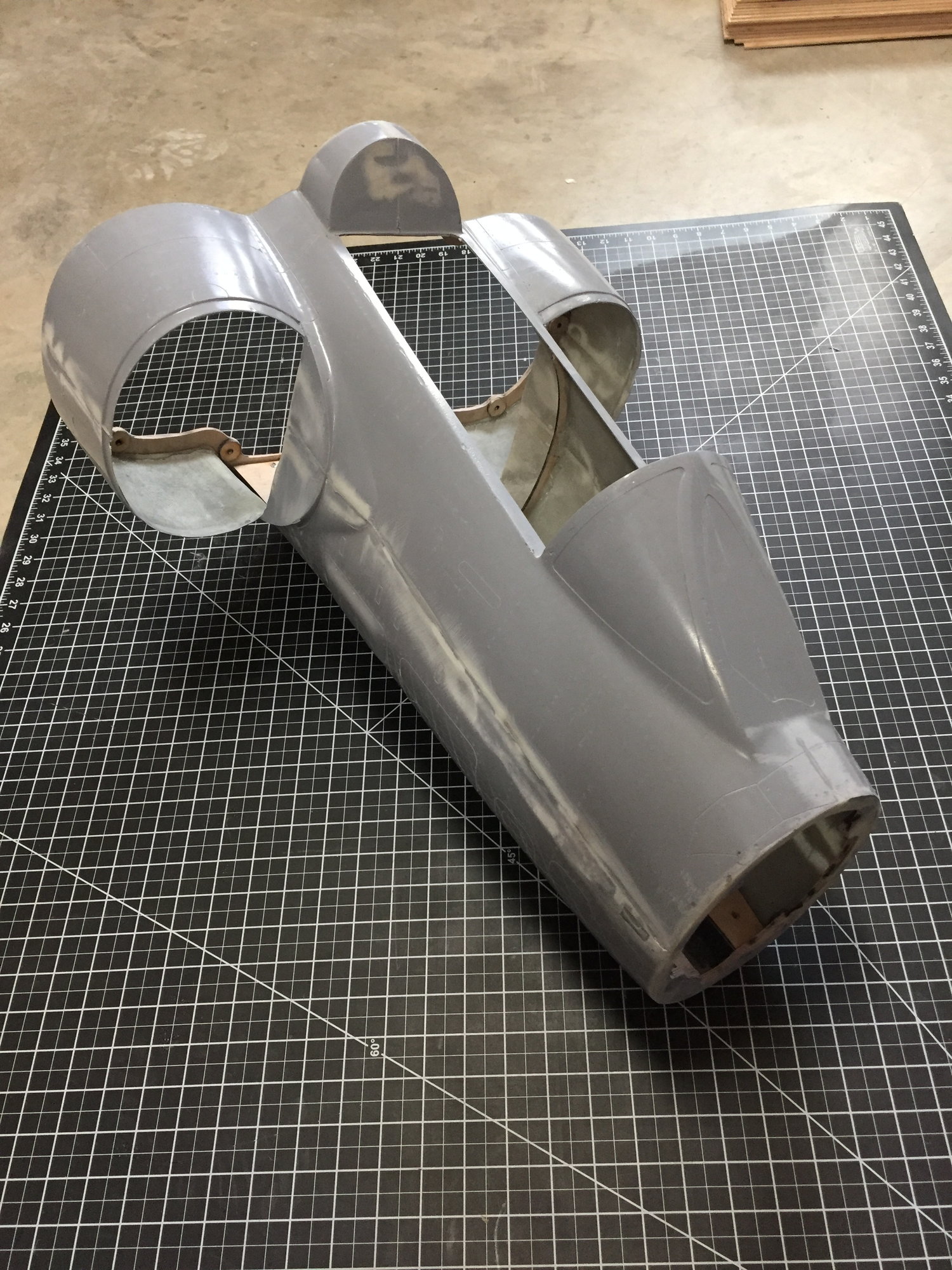
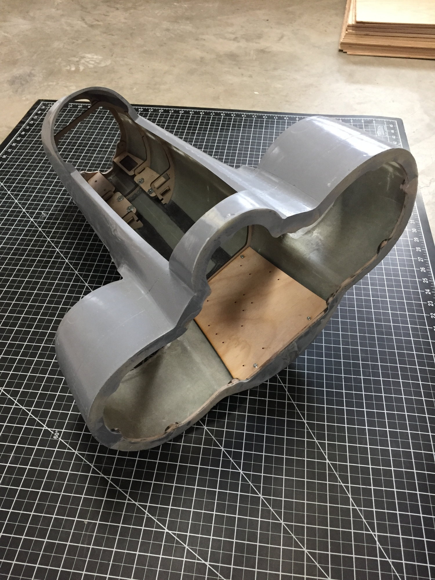
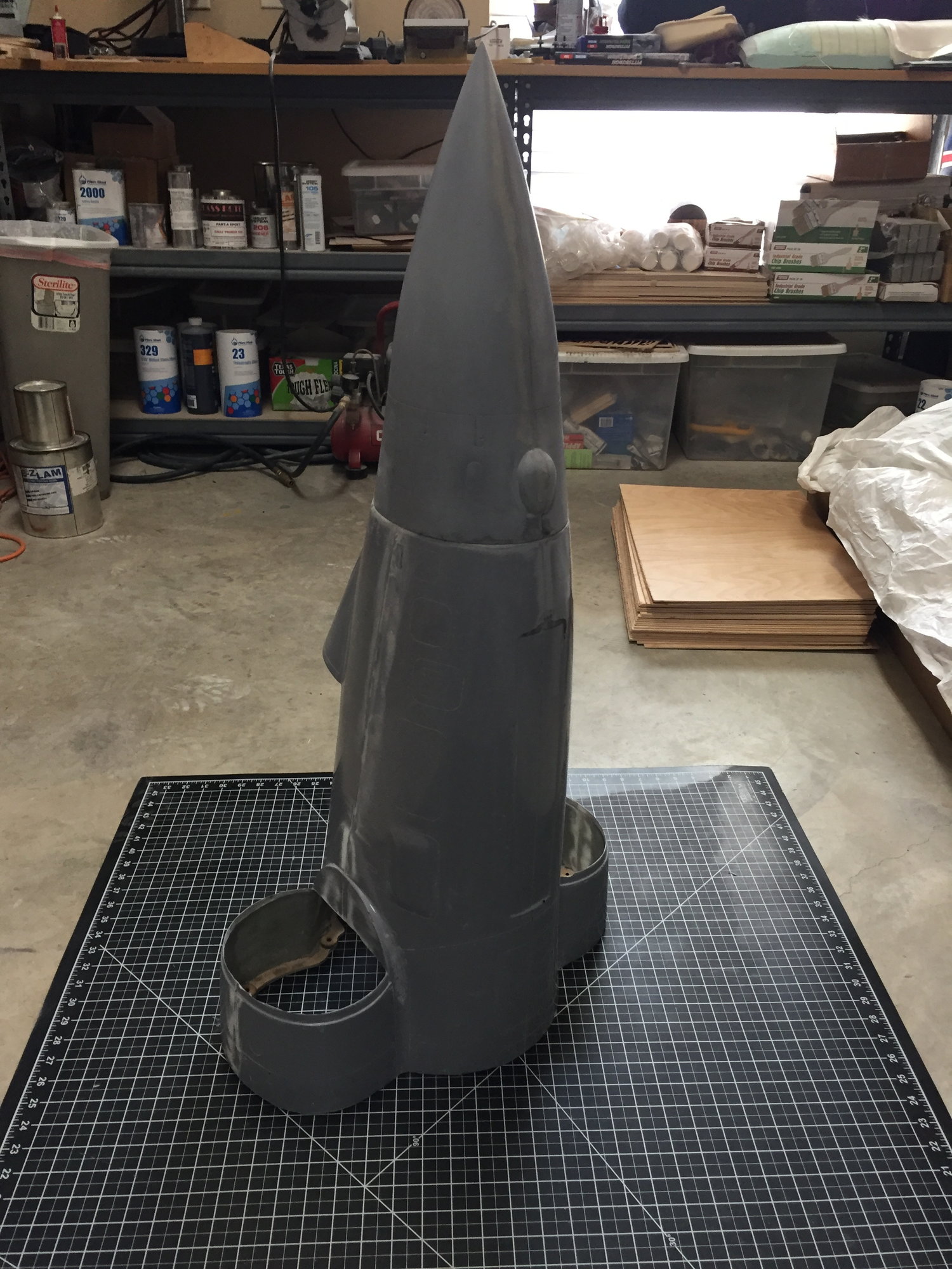
I finished the forward fuselage and pulled it from the mold. Initially it looked good, but I found a few surface voids on the lower half which wasn't properly vacuum bagged. I think with some filler it should be usable, at least for the prototype. Otherwise, I am happy and it feels relatively light coming in at 2lb 2oz.
Going to spend some time cleaning it up and I'll probably spray another coat of primer to seal it all in and make it look reasonable.
Paul
Going to spend some time cleaning it up and I'll probably spray another coat of primer to seal it all in and make it look reasonable.
Paul
11-18-2019, 07:20 PM
#336
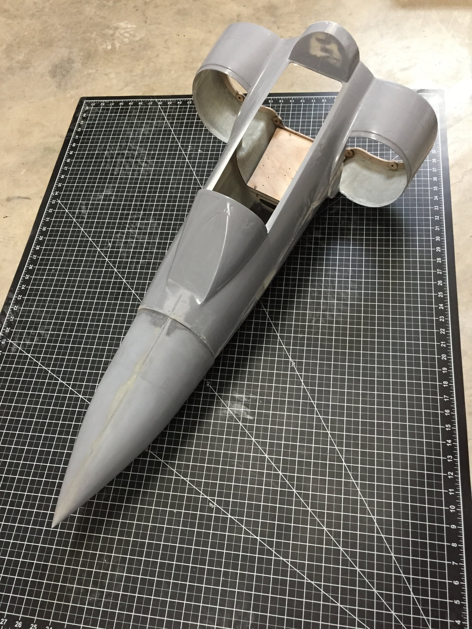
With some filling, sanding and another coat of primer I am happy with the forward fuselage, at least good enough for the first flight.
I have also made a nose gear door, with both internal and external surface detail. The door plug was 3D printed. The inner surface includes mounting pads for the 3 offset hinges, with the pads set to have the hinges all aligned. Hopefully this should make installing the door hinges a lot simpler and neater.
The first attempt at the nose gear door with a foam core came out too thick, so it wouldn't sit flush with the recess in the fuselage. A second one was made using 5 layers of 9oz glass and this one fits perfectly and feels very stiff.


Paul
I have also made a nose gear door, with both internal and external surface detail. The door plug was 3D printed. The inner surface includes mounting pads for the 3 offset hinges, with the pads set to have the hinges all aligned. Hopefully this should make installing the door hinges a lot simpler and neater.
The first attempt at the nose gear door with a foam core came out too thick, so it wouldn't sit flush with the recess in the fuselage. A second one was made using 5 layers of 9oz glass and this one fits perfectly and feels very stiff.
Paul
11-30-2019, 05:36 PM
#337
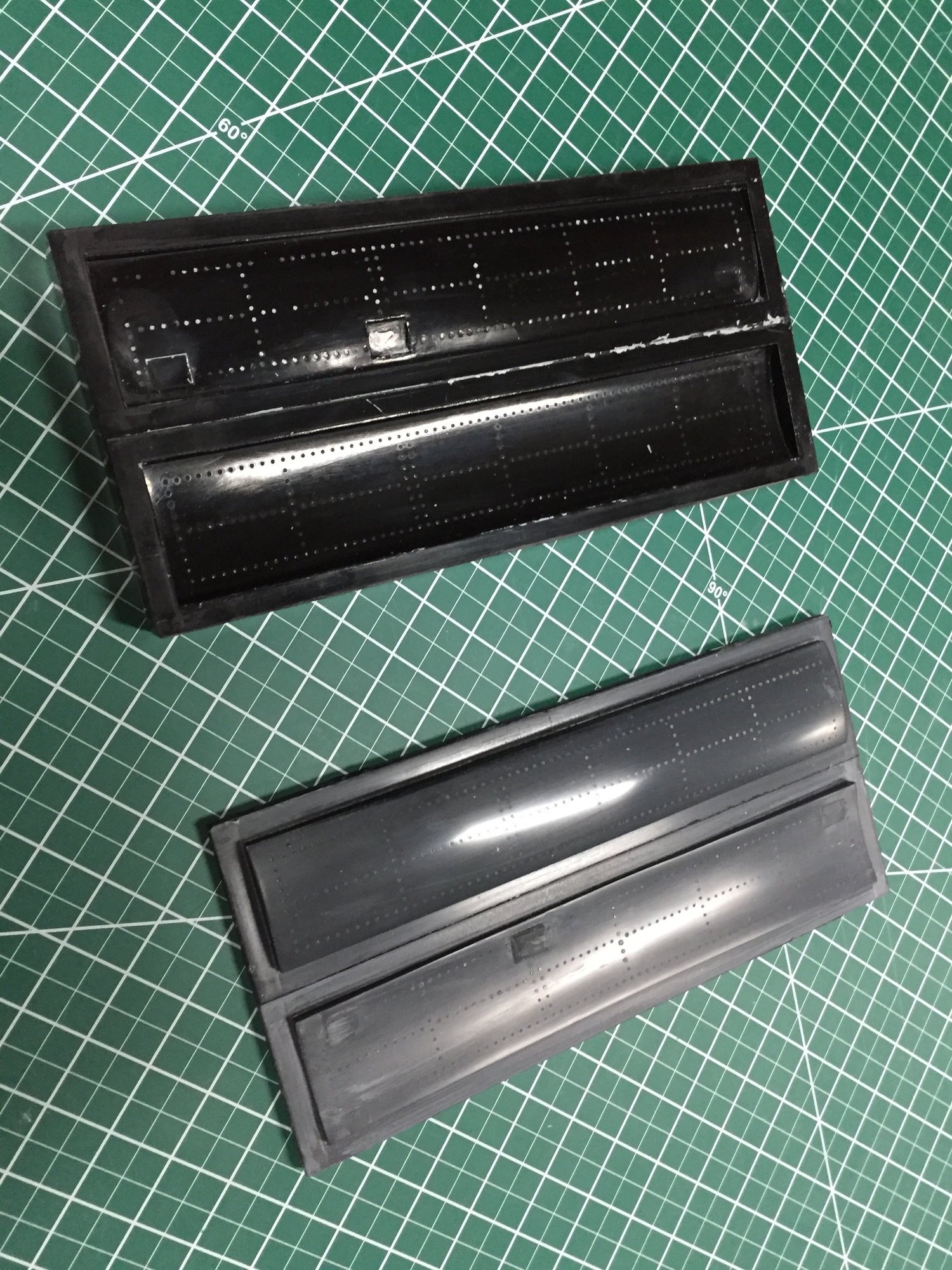
Added the hinges to the nose gear door. The molded in pads ensured that the hinge line worked out with minimal shimming.
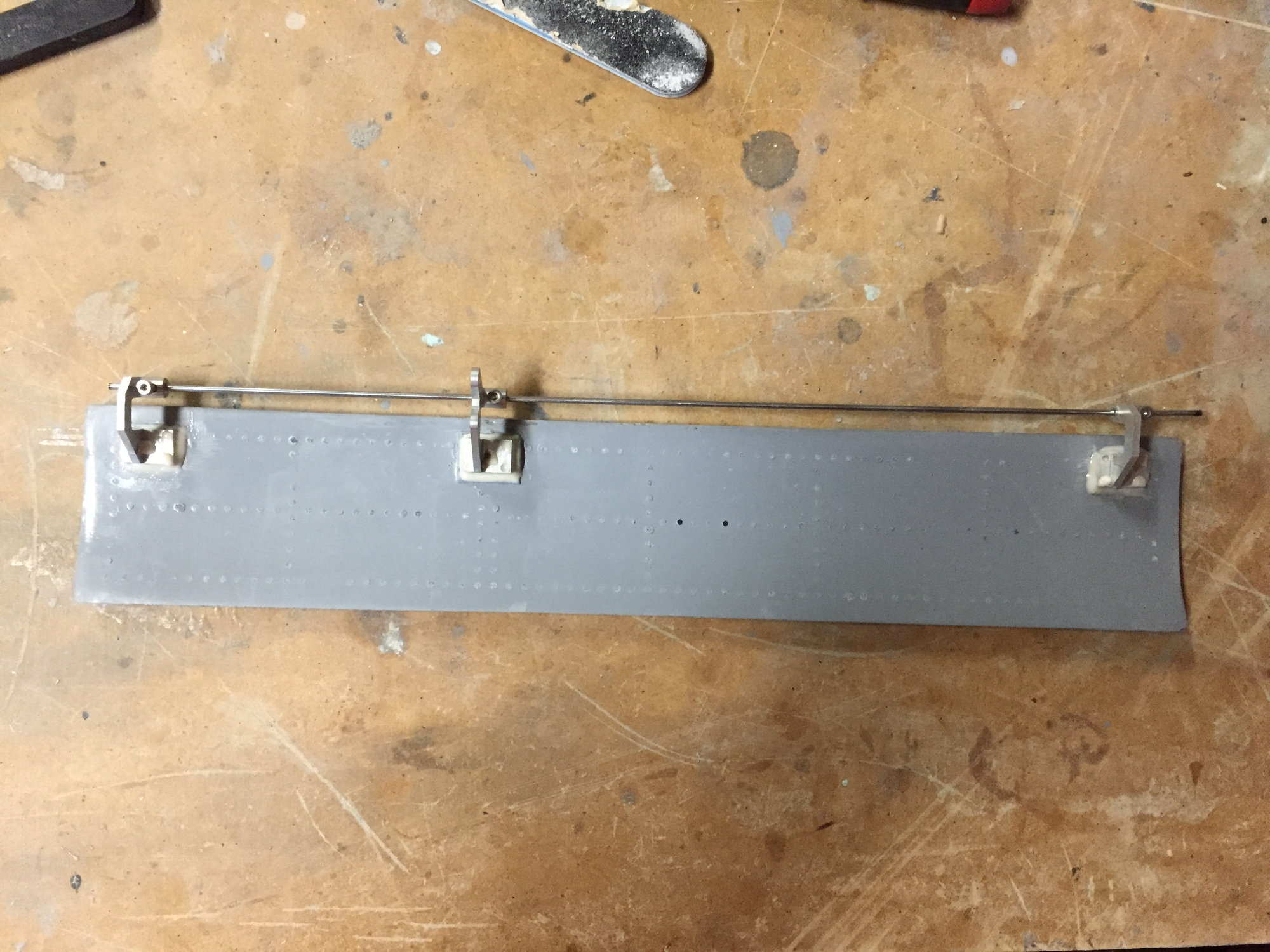
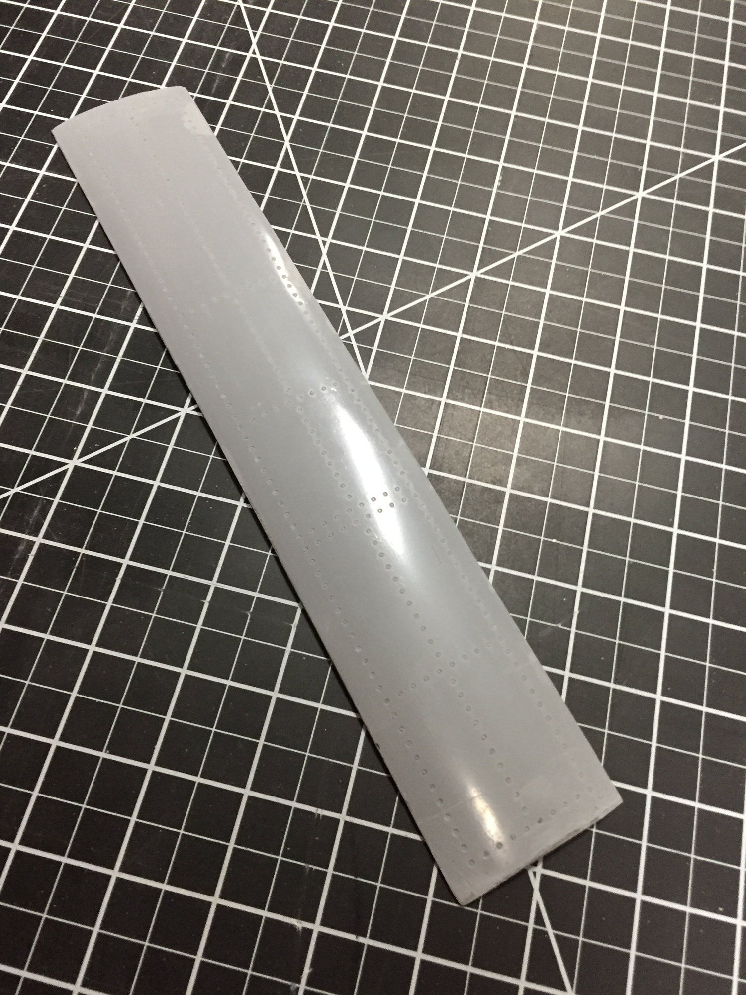
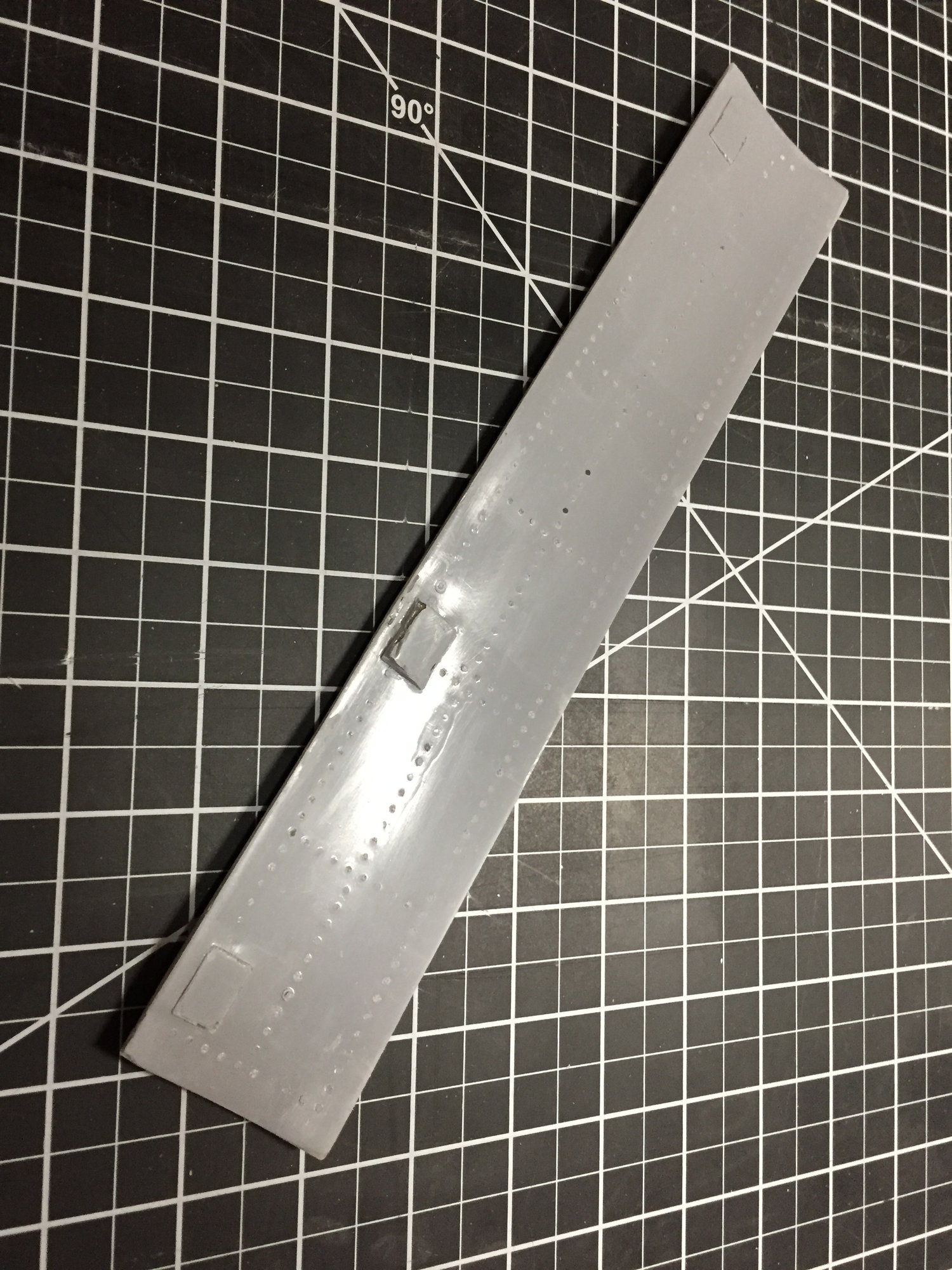
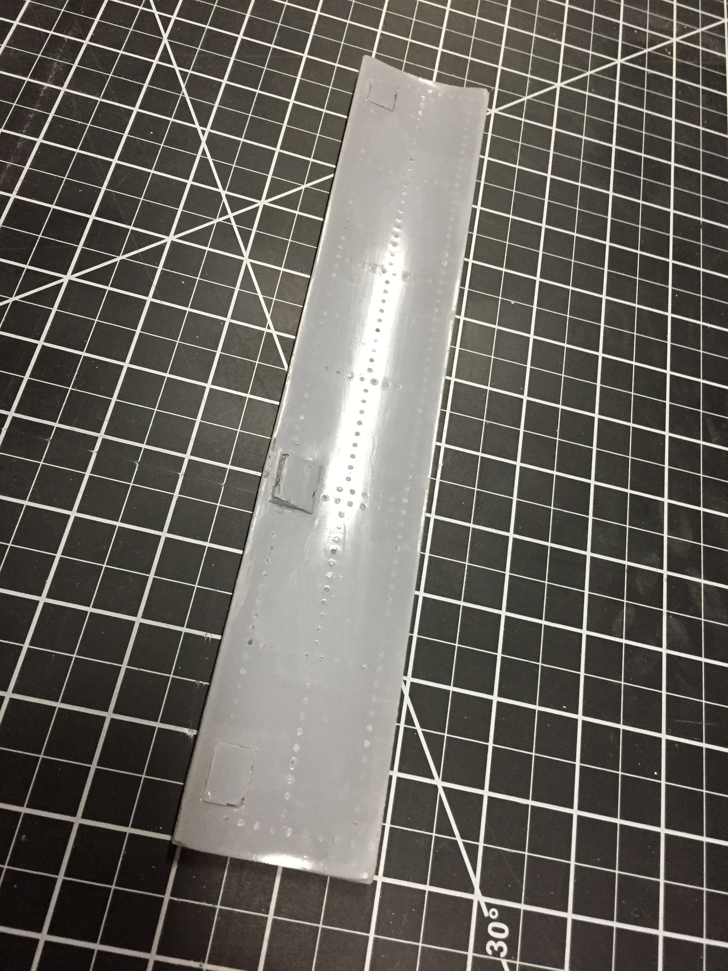
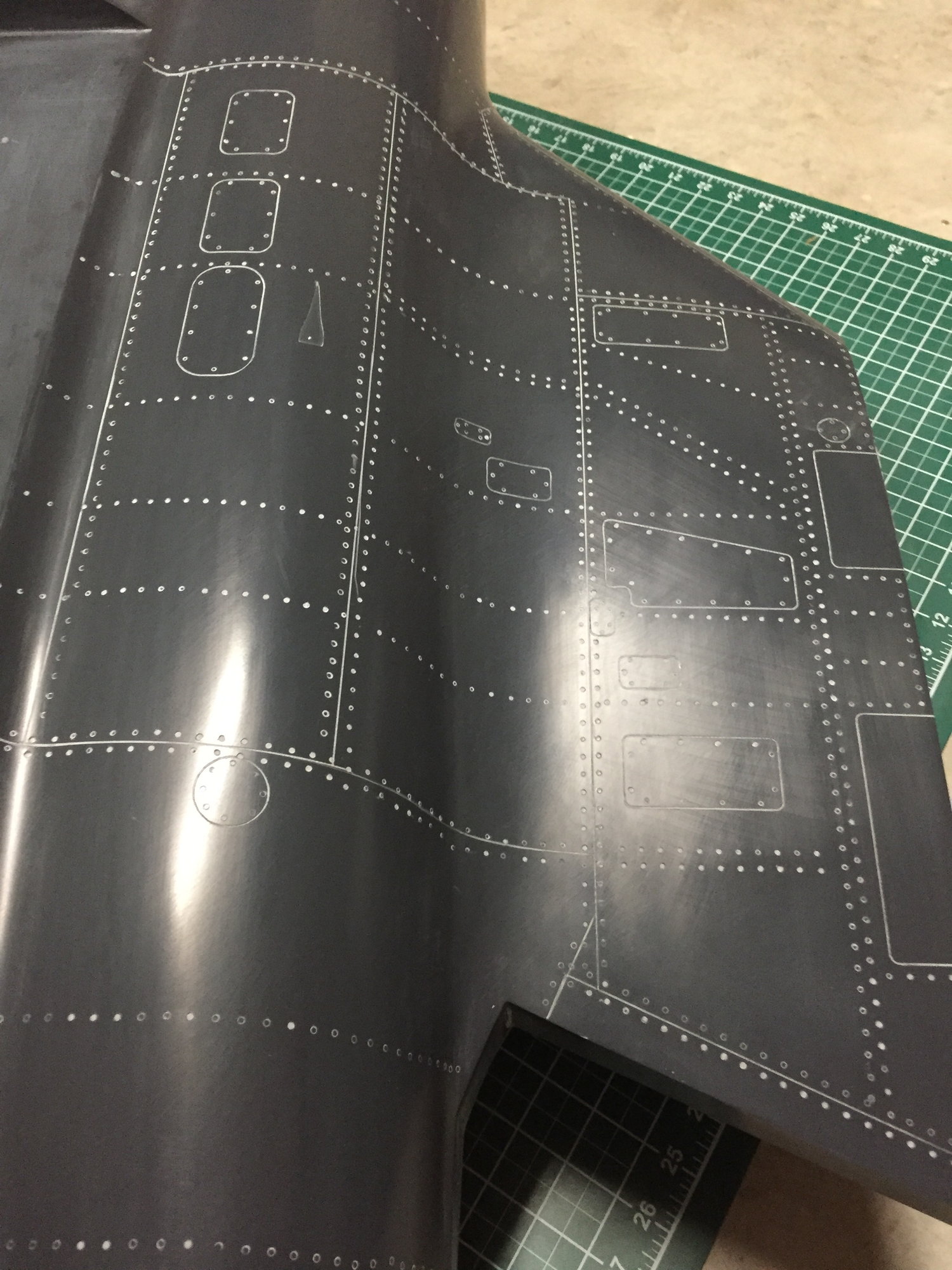
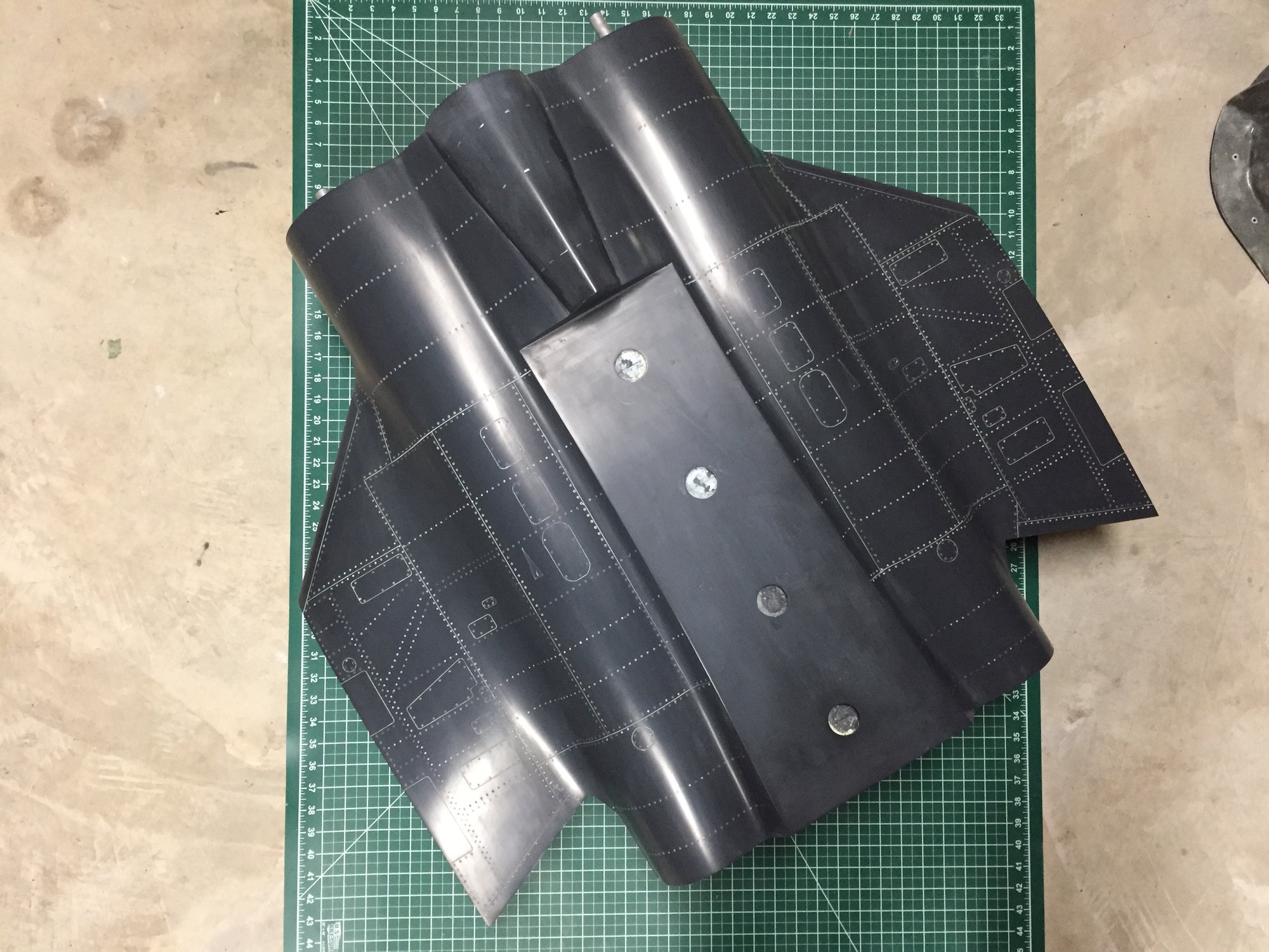
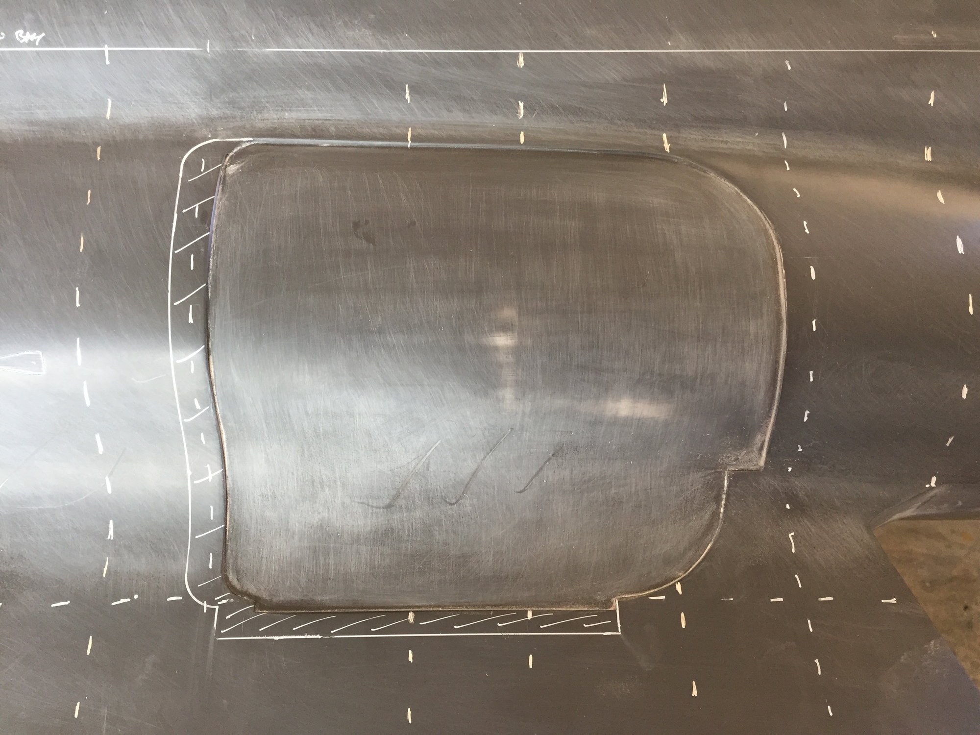
I've also started adding the surface detail to the center fuselage. The upper surface is essentially done. Next up will be to do the same to the lower surface.
Paul
I've also started adding the surface detail to the center fuselage. The upper surface is essentially done. Next up will be to do the same to the lower surface.
Paul

 12-15-2019, 11:09 AM
#340
I've been spending a lot of time on the computer refining the structural layout for the center fuselage. I had the basics done a while ago, but I needed to go and finalize all the various ribs and frames with the necessary cutouts and interlocking pieces. I also had to find a home for the inner flap servo.
As I was doing this, I discovered that, similar to the nose gear door cutout, that the main gear door cutouts were too small for the as-built main gear. With the constraints of the main wing attachment frames/ spars limiting the aft movement of the gear, I ended up having to extend the forward edge of the gear doors 14mm and the outboard edge 10mm. Hopefully no-one will notice.
I modeled the Intairco offset hinges and set the hinge line for the main gear doors - I had to deal with a clash with the retract units by moving one of the hinges aft and trimming off the lugs from the hinges. I have yet to work out the drive linkage placement between the main leg and the door.
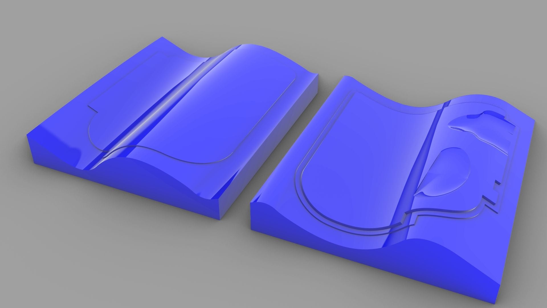
The main gear doors were designed with a 1.5mm outer glass skin and then a 3mm doubler (from Airex foam) to add stiffness to what is a very large door. I have to deal with making some cutouts (dents) on the inner surface to clear the wheel and leg with the gear retracted, so still some design work left on the main doors before making the plug. My intention is to 3D print the plugs just like the nose gear door.
I still need to work on the engine mounts area.
Paul
As I was doing this, I discovered that, similar to the nose gear door cutout, that the main gear door cutouts were too small for the as-built main gear. With the constraints of the main wing attachment frames/ spars limiting the aft movement of the gear, I ended up having to extend the forward edge of the gear doors 14mm and the outboard edge 10mm. Hopefully no-one will notice.
I modeled the Intairco offset hinges and set the hinge line for the main gear doors - I had to deal with a clash with the retract units by moving one of the hinges aft and trimming off the lugs from the hinges. I have yet to work out the drive linkage placement between the main leg and the door.
The main gear doors were designed with a 1.5mm outer glass skin and then a 3mm doubler (from Airex foam) to add stiffness to what is a very large door. I have to deal with making some cutouts (dents) on the inner surface to clear the wheel and leg with the gear retracted, so still some design work left on the main doors before making the plug. My intention is to 3D print the plugs just like the nose gear door.
I still need to work on the engine mounts area.
Paul
Last edited by JSF-TC; 12-15-2019 at 11:15 AM.
12-15-2019, 11:31 AM
#341

Another level of prototyping, some of the big manufacturers don’t have your level of 3-D modelling to check this stuff-probably why none have attempted this before, there is $100,000 worth of CAD work there.
When this stands on it wheels the first time sit down and reflect on what you have achieved, when it lands from the first flight send me your bar bill...
When this stands on it wheels the first time sit down and reflect on what you have achieved, when it lands from the first flight send me your bar bill...
12-15-2019, 04:38 PM
#342
Dave,
Thanks for the compliments. Assuming it survives its first flight, I'll take you up on a beer next time I'm in the UK.
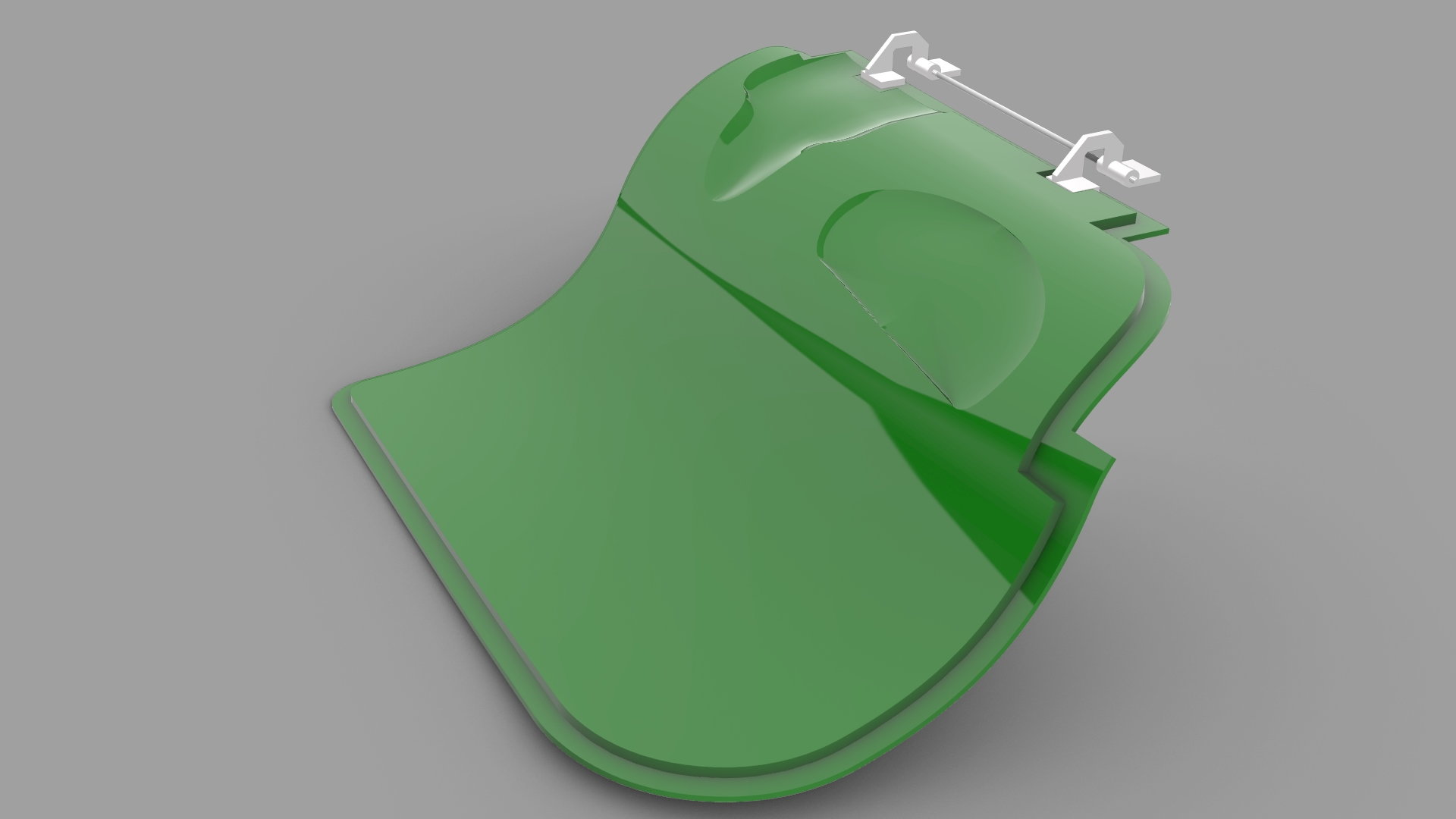
I finished the main gear doors with the necessary clearance cutouts in them to clear the gear when retracted. These should now be ready to make into plugs.
Paul
Thanks for the compliments. Assuming it survives its first flight, I'll take you up on a beer next time I'm in the UK.
I finished the main gear doors with the necessary clearance cutouts in them to clear the gear when retracted. These should now be ready to make into plugs.
Paul
12-16-2019, 01:00 AM
#343

Hi Paul, I have been silently looking at your thread for some time, very nicely done, great piece of engineering!
Looking at your last fuselage design just a small note. The main former where gear and main wing spar meets has a hole not connected on the lower side. I had something similar on a model long time ago and it's prone to structural failure on a hard landing which could be unnoticed until next flight. Not sure if I can see it right but if you look on my addition below you see what I mean. The red line would be the tensile area prone to failure, I would connect it simply as drawn in purple. Maybe I did not see it correctly, anyway better safe than sorry!
Again, great work done here!
Cheers,
Gerald
12-16-2019, 07:41 AM
#344
Gerald,
Thanks for your comments.
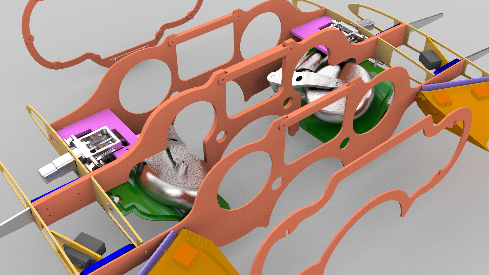
I agree that Frame 3 is not the best structural arrangement, but if you look at a section through the fuselage at Frame 3 with the gear retracted and pipes installed, you will see that there is no space available to close out that frame.

In order to try to ensure adequate structural strength, I am planning on making Frame 3 out of 3 layers of 1/8" 5-ply. Two layers will have the cut-outs necessary for the ribs and retract plate, but the 3rd frame layer will omit these cut-outs in order to eliminate any potential weak points. I may even go to 4 layers, 2 of each. That would make that frame 1/2" thick. See frame layouts below.
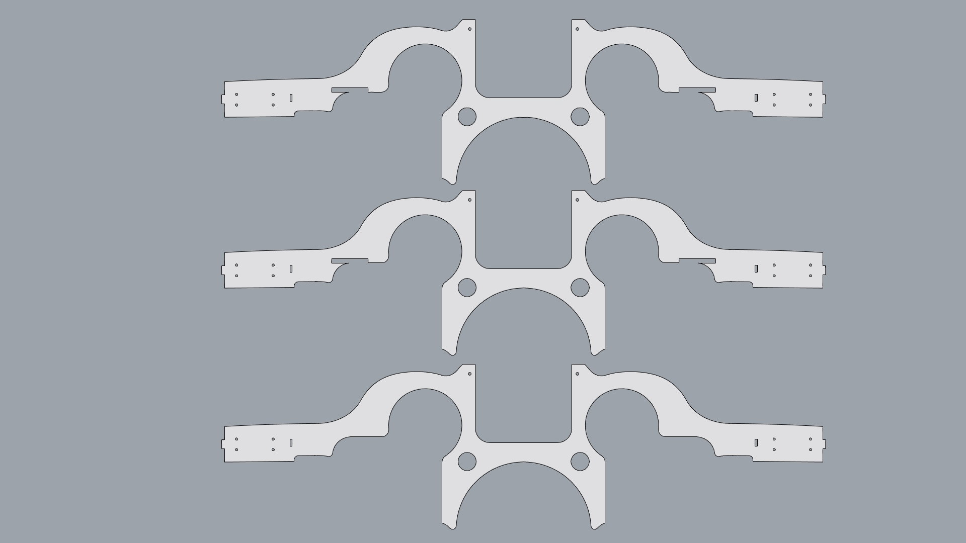
If you can think of a better way please let me know.
Paul
Thanks for your comments.
I agree that Frame 3 is not the best structural arrangement, but if you look at a section through the fuselage at Frame 3 with the gear retracted and pipes installed, you will see that there is no space available to close out that frame.
In order to try to ensure adequate structural strength, I am planning on making Frame 3 out of 3 layers of 1/8" 5-ply. Two layers will have the cut-outs necessary for the ribs and retract plate, but the 3rd frame layer will omit these cut-outs in order to eliminate any potential weak points. I may even go to 4 layers, 2 of each. That would make that frame 1/2" thick. See frame layouts below.
If you can think of a better way please let me know.
Paul
Last edited by JSF-TC; 12-16-2019 at 07:55 AM.
 12-16-2019, 10:29 AM
#347

Gerald,
Thanks for your comments.
I agree that Frame 3 is not the best structural arrangement, but if you look at a section through the fuselage at Frame 3 with the gear retracted and pipes installed, you will see that there is no space available to close out that frame.
In order to try to ensure adequate structural strength, I am planning on making Frame 3 out of 3 layers of 1/8" 5-ply. Two layers will have the cut-outs necessary for the ribs and retract plate, but the 3rd frame layer will omit these cut-outs in order to eliminate any potential weak points. I may even go to 4 layers, 2 of each. That would make that frame 1/2" thick. See frame layouts below.
If you can think of a better way please let me know.
Paul
Regarding this high stress are I had a similar problem with my Rotkoski Sabre which I modified to have removeable wing panels.
I faced the ply formers with 3 mm carbon plate, massively stronger but lightweight.
Flight test showed this to be fine.
Good luck with the first flights, next time you are in UK the champers is on ice !!
12-16-2019, 10:58 AM
#348
I see, that's always the search and compromise of scale/complexity/workable arrangement. As suggested, carbon fibre sandwiched between the layers will massively increase strength, 160gram wil do the job.
I like your 3D drawings, something I still want to learn in due time, I still draw everything 2D, Autocad.
Cheers,
I like your 3D drawings, something I still want to learn in due time, I still draw everything 2D, Autocad.
Cheers,
12-16-2019, 11:01 AM
#349
I wouldn’t over do that former. Just capping it with carbon in the skin will make it incredibly strong. If the skin does not flex there neither will the former.
12-16-2019, 06:59 PM
#350
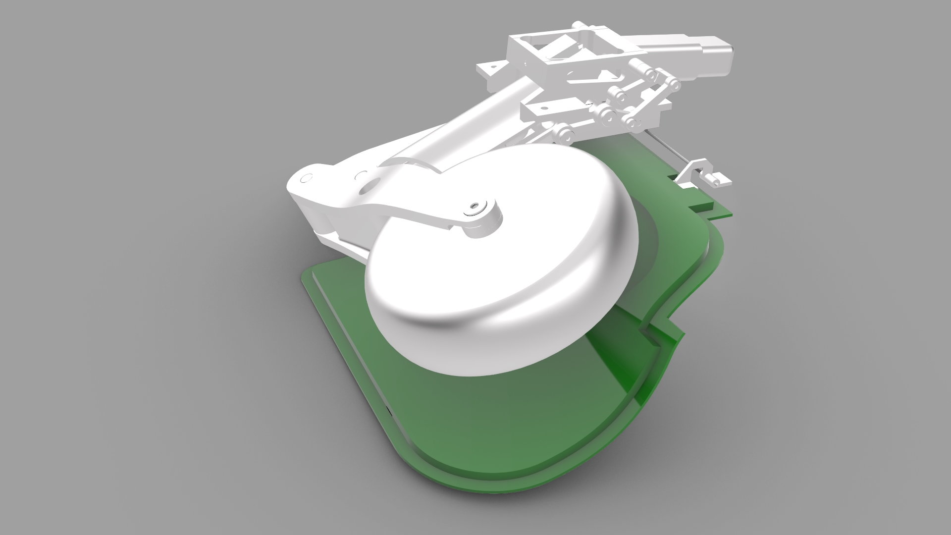
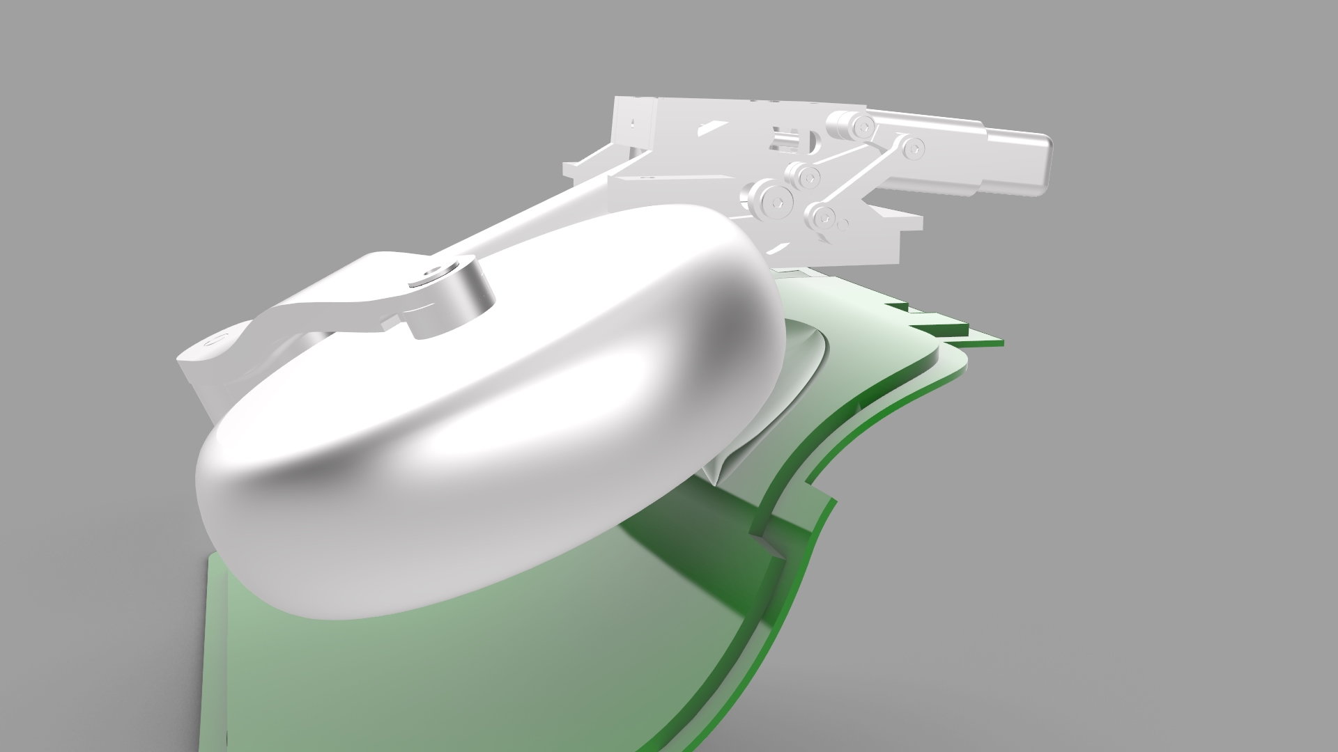
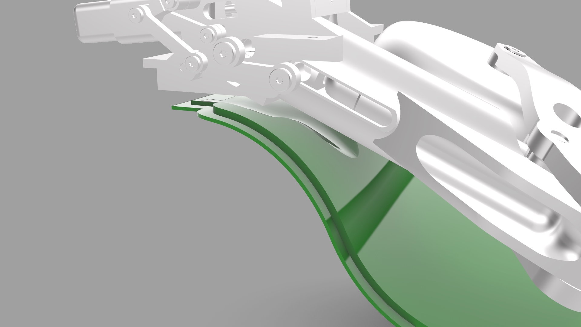
Working out the main gear door drive linkage geometry was a process of trial and error. While there are numerous solutions, very few give a practical solution in terms of finding a suitable mounting point on the main gear legs.
I think I have finally settled on the geometry below. Not a great pull angle when retracted, but hopefully sufficient closing power. I need to drill the gear legs and make a small stand-off for the ball-link.
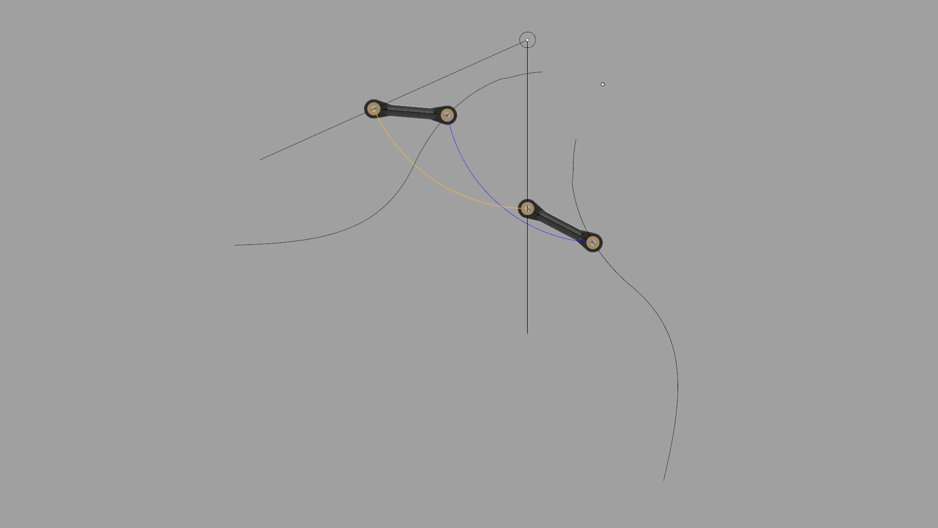

Paul
I think I have finally settled on the geometry below. Not a great pull angle when retracted, but hopefully sufficient closing power. I need to drill the gear legs and make a small stand-off for the ball-link.
Paul