Control horn install geometry question
#1
Over the years I have always installed my control horns with the pivot holes lined up with the hinge line of whatever surface they are on.
What would be the effect of moving the horn so the holes are before or after the hinge line? I am having a hard time figuring out what the effect might be. I imagine there would be a change in deflection, just not sure in which direction or how much.
John
What would be the effect of moving the horn so the holes are before or after the hinge line? I am having a hard time figuring out what the effect might be. I imagine there would be a change in deflection, just not sure in which direction or how much.
John
#2

I have had large jets that did not allow lining up the holes with the hinge line. It did not effect the flying charactirictics but needed more movement from the servo arm to get the needed deflection. also, lining them up with hinge line make it easier to make sure they are in same line / distance (assuming servos are in the same position on both sides)
#4

Moving the control horn hole before or after the hinge line won't result in more throw in both directions.
What you will get is differential, more movement one way, less in the other, until/if you decide to tweek the end point adjustment via the radio.
What does effect the throw is the height of the control horn hole above the control surface. Longer horns mean less control surface deflection,
short horns mean more deflection.
If you need more movement & can't fit longer servo arms you will need shorter control horns.
#5
Senior Member
Join Date: Feb 2023
Location: Corryton, TN. Fly at Lucky Lane RC Club
Posts: 160
Likes: 0
Received 23 Likes
on
21 Posts
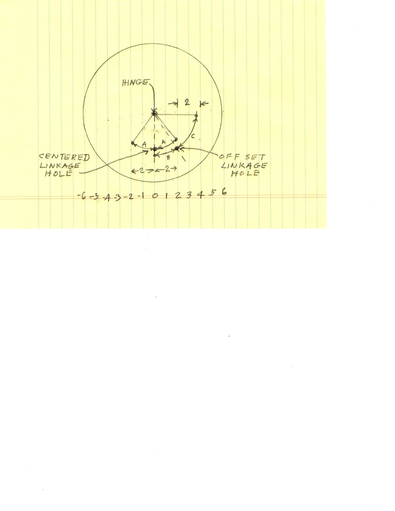
I will start by assuming the driver (servo or 90 degree bell crank) is a rotary output and is centered to provide equal throws in each direction. For illustration purposes, envision the control surface and the control horn hole locations being projected onto a wheel that rotates about the hinge line (See the illustration). The wheel will rotate until the hole has moved a lateral displacement equal to the linkage movement. The illustration shows the amount of wheel rotation (A) in each direction by a displacement of 2 lateral units is equal when the linkage hole is directly below the hinge (axle) line. However, when the linkage hole is offset an extreme amount to the right of the hinge line as shown on the illustration, it can be seen that the same linkage displacement of 2 units to the left causes less angular displacement (B) and that it can be impossible to get a full 2 unit displacement to the right because now the rod is pulling directly against the hinge line. It can be seen that the angular rotation (C) is much greater from the linkage displacement to the right than it is to the left.
This same effect is also used to provide differential aileron movement to get more up aileron than down to correct for adverse aileron yaw. They do this by using 60 degree bell cranks instead of 90 degree bell cranks.
To know exactly how much differential movement will result from a displaced control horn location would require pulling out your old high school geometry and trigonometry books and doing the math, but for practical purposes, the differential throws will become noticeable when the linkage holes are off by about 1/8 inch and will become quite noticeable by 1/4" offset when using a standard 3/4" control horn. The easiest thing is to continue mounting the control horn hole locations directly under the hinge line and use end point adjustments on the transmitter to produce any desired differential throws.


