


1/7th F-14D Scratch build thread *building started*


 11-13-2013, 08:55 PM
#1280
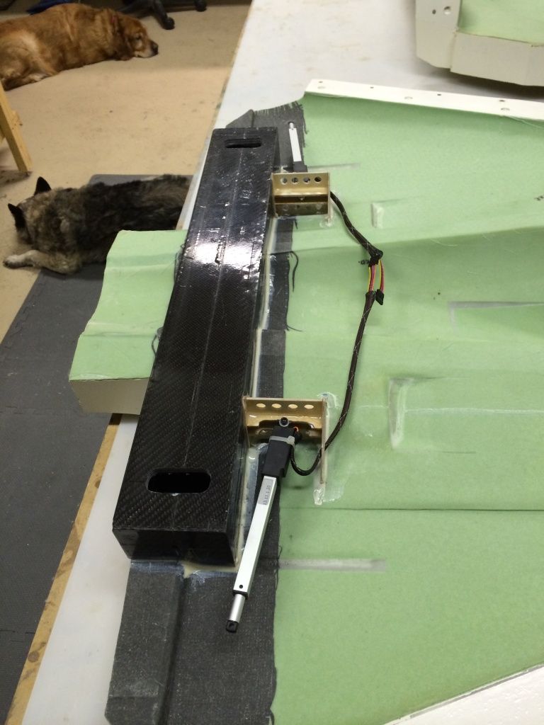
Sweep actuator mounts and actuators are installed:
And here is a shot of the entire internal structure with the top halves of the mold removed:
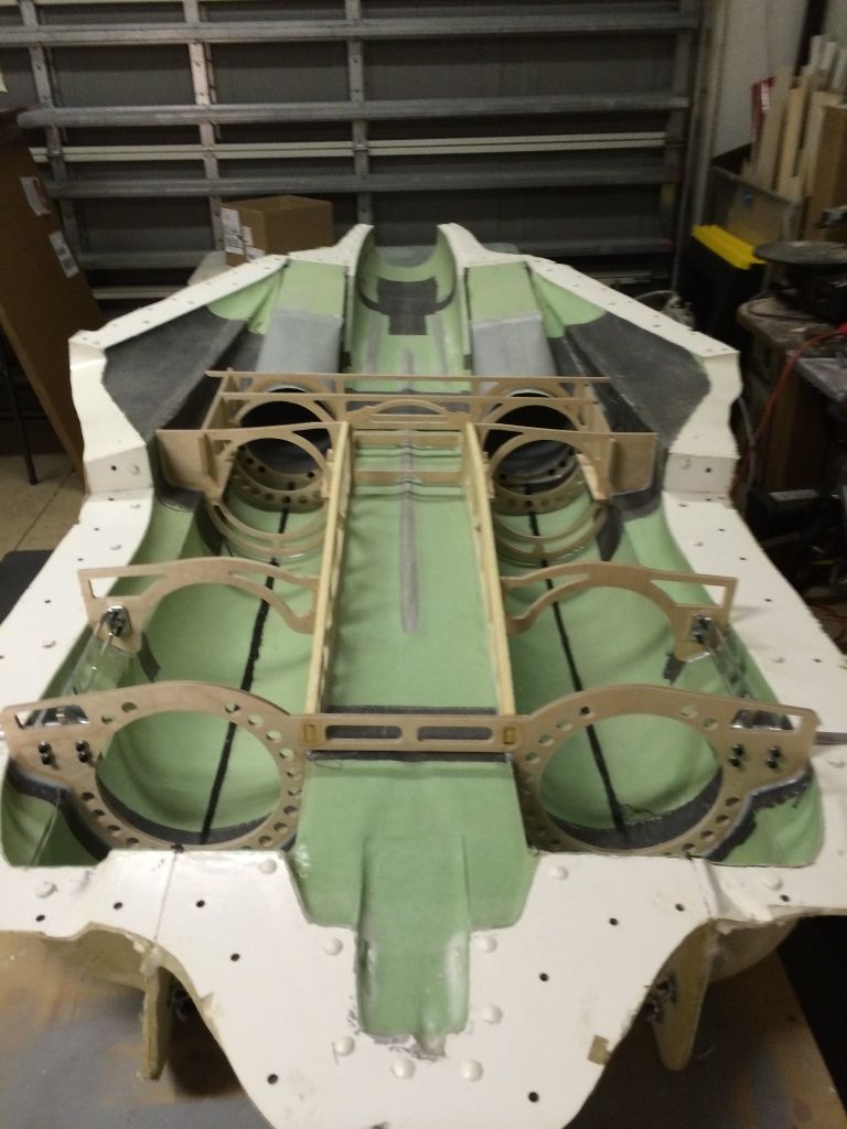
As it is right now, everything is installed other than some UAT and equipment mount plates, but all of this stuff can be installed later.

And here is a shot of the entire internal structure with the top halves of the mold removed:

As it is right now, everything is installed other than some UAT and equipment mount plates, but all of this stuff can be installed later.
11-14-2013, 02:21 AM
#1281

Thomas, have you some video on how actuators works?
Besides I don't understand where they will be positioned towards the pivot, it seems to me that they're too much near it but I could be wrong, of course...
Besides I don't understand where they will be positioned towards the pivot, it seems to me that they're too much near it but I could be wrong, of course...
11-14-2013, 06:55 AM
#1282
No video from me, but lots on youtube under firgelli.
These are linear actuators and have just under 50lbs of force each. Since they are linear, you get that 50lbs of force all the time, not like a regular servo where the further out on the arm you get, the less effective torque you have.
It only appears to be close to the pivot, in actuality, its a good 4-5" away, i chose not to put it aft of the spar box like other manufacturers because i disnt want it over the turbine for 2 reasons. 1. Heat and 2. Ease of maintenance.
The wings can still be removed, it will just be a little more difficult as the actuator connection pin/bolt will have to be removed from the wing through the main landing gear wheel well
11-14-2013, 08:12 AM
#1283
Good choice for those actuators, sure the wing sweep mechanism cannot suffer of lack of torque.
Got even some videos, thank you.
I don't know if your original plan was to maintain the wing sweep between 20� and 68� (I've still to search about it from the very beginning of this thread), if so will you be able to obtain it even after moving the actuators to a different position?
Got even some videos, thank you.
I don't know if your original plan was to maintain the wing sweep between 20� and 68� (I've still to search about it from the very beginning of this thread), if so will you be able to obtain it even after moving the actuators to a different position?


 11-14-2013, 02:40 PM
#1286
I'm going to a fly-in on saturday and this is going... So i've got to spend this evening and tomorrow prepping for that, and getting this ready in a few ways (install stab servo's, reinforce vertical stab spar sockets, hinge rudders, etc etc). for display.
11-14-2013, 03:35 PM
#1288

I am still following this thread Thomas.. Amazing work. From what I can see, the quality of your work rivals or exceeds anything out of even the best model factories.
It is hard to believe that you can do all this, basically as a hobby, by yourself, in your home.
Must be feel fantastic to see your creation in one piece..(nearly)
Roger
It is hard to believe that you can do all this, basically as a hobby, by yourself, in your home.
Must be feel fantastic to see your creation in one piece..(nearly)
Roger


 11-14-2013, 06:59 PM
#1295
I am still following this thread Thomas.. Amazing work. From what I can see, the quality of your work rivals or exceeds anything out of even the best model factories.
It is hard to believe that you can do all this, basically as a hobby, by yourself, in your home.
Must be feel fantastic to see your creation in one piece..(nearly)
Roger
It is hard to believe that you can do all this, basically as a hobby, by yourself, in your home.
Must be feel fantastic to see your creation in one piece..(nearly)
Roger
Thanka roger,
Anyone can do it, i just takes time, money, patience, determination and lots of research!
11-14-2013, 07:02 PM
#1296
Thanks to everyone else for the kind words, this has definitely been and will continue to be a labor of love. Its hard to believe i have been attempting to get an F14 to this stag of completion for 15+ years, and am finally making that dream become a reality.
A few set backs as far as the wing pivot assembly is going, i some how messed up the dimensions of the pivot brackets so i have to have another set machined. No big problem with that, except i just spent the last of my spare cash on a CNC router and some servo's. So it'll have to wait a bit to get the brackets machinee along with the remainder of the wheels and tires and some other parts needing machined.
A few set backs as far as the wing pivot assembly is going, i some how messed up the dimensions of the pivot brackets so i have to have another set machined. No big problem with that, except i just spent the last of my spare cash on a CNC router and some servo's. So it'll have to wait a bit to get the brackets machinee along with the remainder of the wheels and tires and some other parts needing machined.
 11-14-2013, 08:04 PM
#1298
MOAR POWR! I mean more progress 
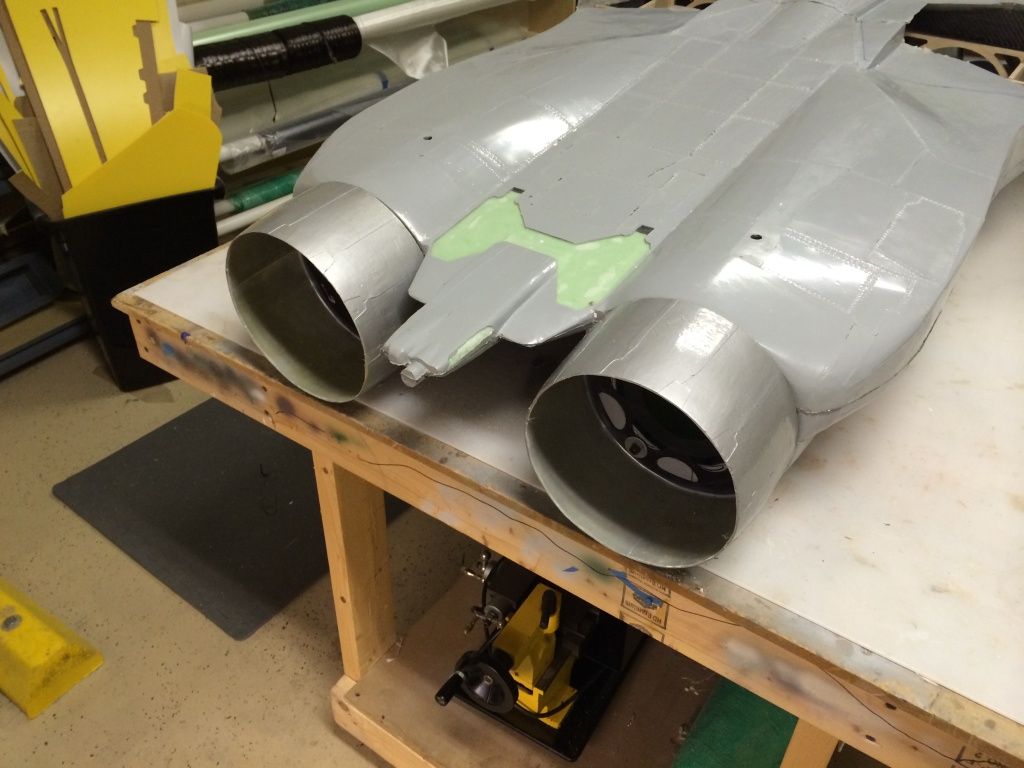
Exhaust nozzle's mounted and the attachment plates letting the hysol cure:
I then sanded the inlet ramp layup on the LE of the ramps down so they could be clamped down to give a nice constant thickness along their width. Then hysol was smooshed into the gap and the 2 halves clamped down. I didn't join this portion of the molds on purpose as the thickness here I have never been happy with. This should eleviate some of that unhappiness:
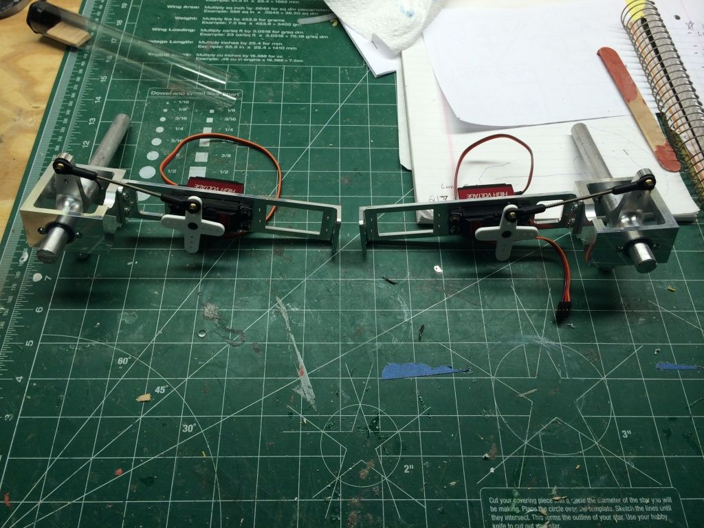
Then I removed the horizontal stab mechanisms and started working on the control linkages. There is a nifty little spreadsheet I got from Oli Nicol's on RCU that allows you to determine the best linkage geometry setup that I plan to use to figure this out. What you see here is just to get through the weekend..
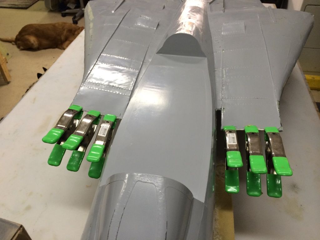
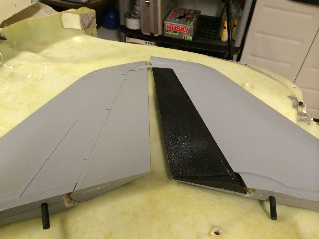
I found some hinges so I drilled the holes for the 3/16" robart hinge points and installed them to the vertical fins. I still need to oblong the rudder leading edges so they can swing side to side, but they atleast lined up with the vertical fin.. (this was the hardest job of the entire project so far! lol)
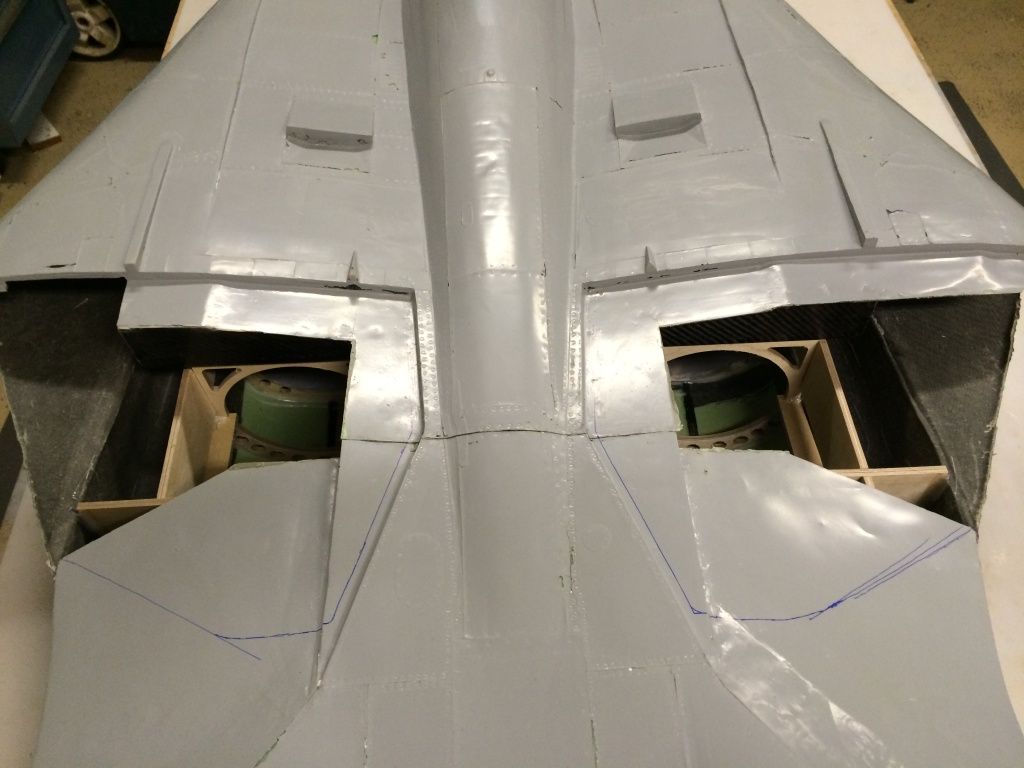
And I started marking the aft top fuselage skin where it will be trimmed under the over wing fairing hatch's to allow more access to the turbine install:
Exhaust nozzle's mounted and the attachment plates letting the hysol cure:

I then sanded the inlet ramp layup on the LE of the ramps down so they could be clamped down to give a nice constant thickness along their width. Then hysol was smooshed into the gap and the 2 halves clamped down. I didn't join this portion of the molds on purpose as the thickness here I have never been happy with. This should eleviate some of that unhappiness:

Then I removed the horizontal stab mechanisms and started working on the control linkages. There is a nifty little spreadsheet I got from Oli Nicol's on RCU that allows you to determine the best linkage geometry setup that I plan to use to figure this out. What you see here is just to get through the weekend..

I found some hinges so I drilled the holes for the 3/16" robart hinge points and installed them to the vertical fins. I still need to oblong the rudder leading edges so they can swing side to side, but they atleast lined up with the vertical fin.. (this was the hardest job of the entire project so far! lol)

And I started marking the aft top fuselage skin where it will be trimmed under the over wing fairing hatch's to allow more access to the turbine install:


