


1/7th F-14D Scratch build thread *building started*
 12-16-2013, 07:59 PM
#1326


Still slowly working on this thing... I've got the majority of the CAM coding for all of the flap and spoiler hinges done. i've also been working on the Slat tracks and sliders as well. Materials for all of the hinges and slat stuff is on the way (except for some carbon tubes). Once the materials arrive, I can get start cutting out all of the parts and get the internal structure stuff glued together and ready to close up the wings.
Flap Hinge Support test pieces:
Spoiler hinge test pieces:
LE slat slider and track test pieces:
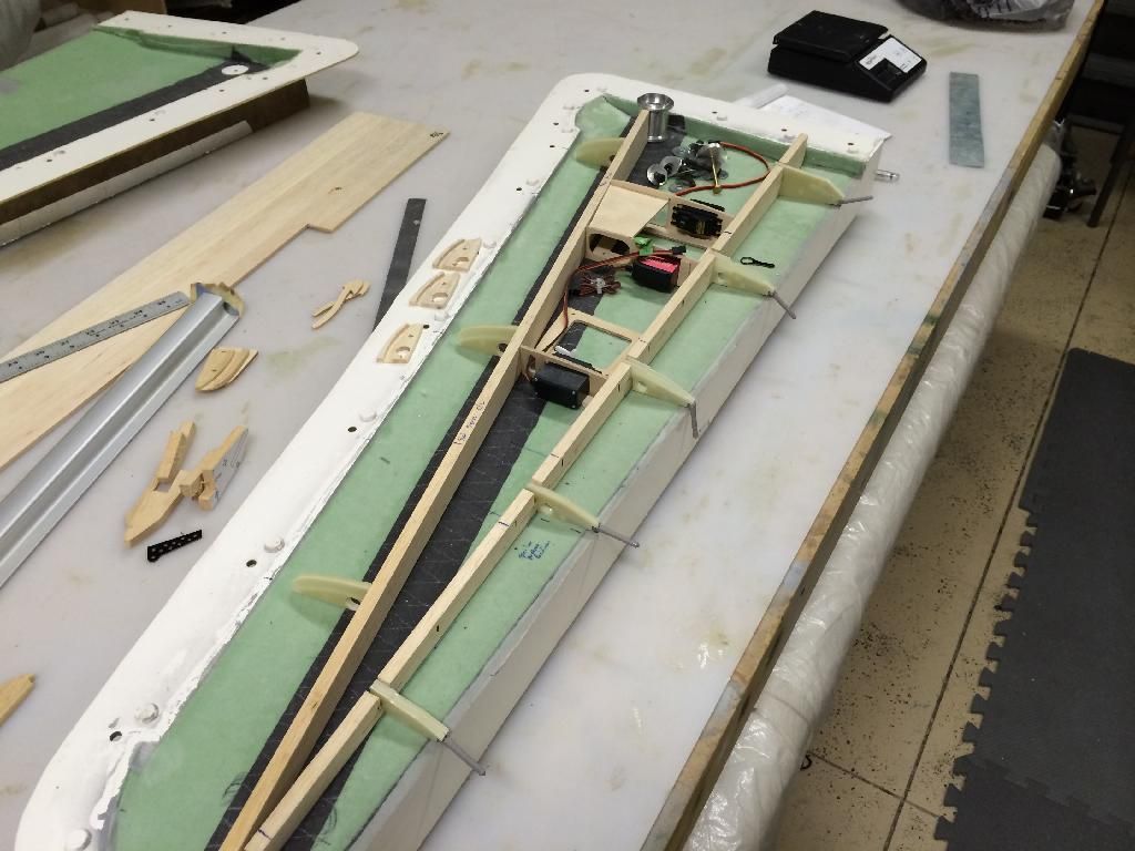
Wing internals showing all of the test pieces mocked into position:
Flap Hinge Support test pieces:

Spoiler hinge test pieces:

LE slat slider and track test pieces:

Wing internals showing all of the test pieces mocked into position:

 12-23-2013, 06:23 PM
#1327
Theres a whole lotta G10 going on. Mostly i finall got motivated to cut out the G10 hinge pieces for the first wing. Of course this motivation came after 8 hours of trying to find a drivetrain vibration in my wifes car, and a chance meeting of my 5lb mini sledge and my left ringe finger. Im the proud owner of a purple and pink ring finger now. Ha
Anyways...
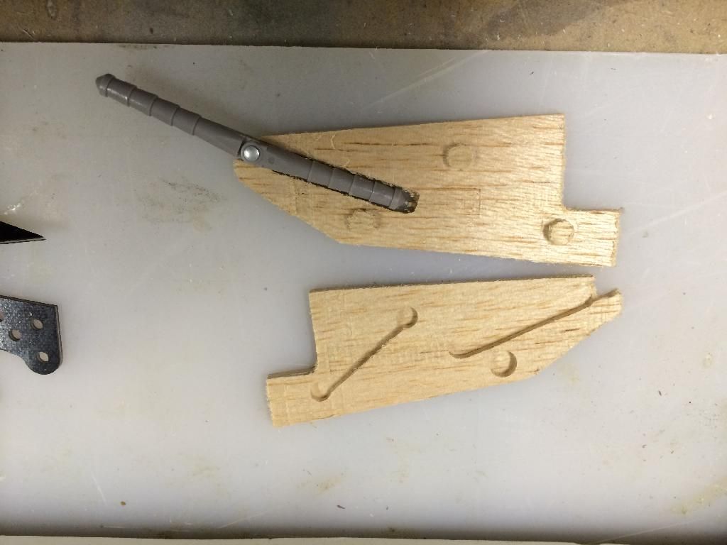
Heres a shot of the overall wing. New in this photo is the machine G10 flap and slat hinges. Each flap hinge half is 3 dimensionally machined from 3/16" G10, then hysoled together to make up one hinge. The same goes with the slat sliders, but they have a .030" cover plate to close up the slots in them.
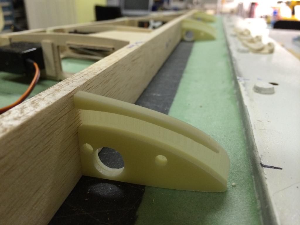
And a shot of the slat track before the cover plate is attached:
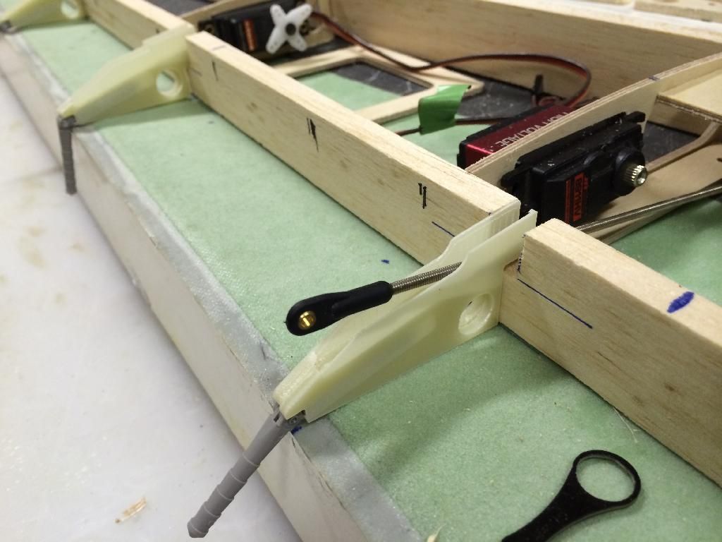
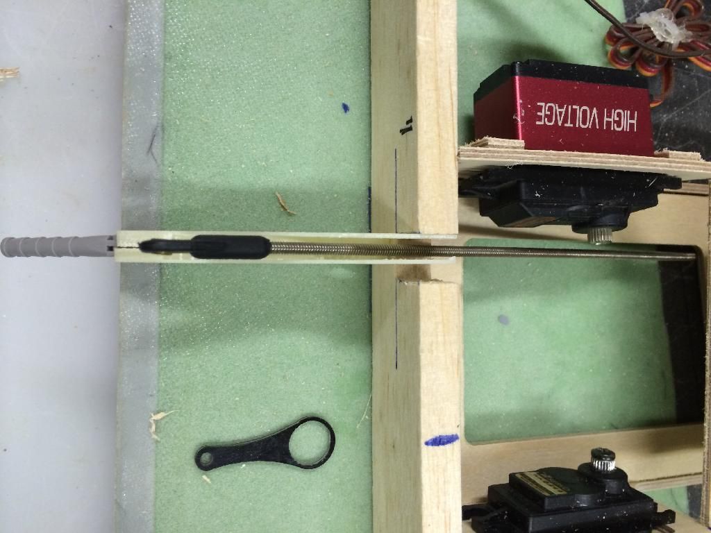
The Second and Third flap hinges have pushrod slots machined into the upper half of each hinge. This slot allows a dubro 4-40 heavy duty ball link to pass through. This is scale for the F-14 and conceals the flap linkages is the scale location. Here are two photos showing a mockup pushrod in place.
Anyways...
Heres a shot of the overall wing. New in this photo is the machine G10 flap and slat hinges. Each flap hinge half is 3 dimensionally machined from 3/16" G10, then hysoled together to make up one hinge. The same goes with the slat sliders, but they have a .030" cover plate to close up the slots in them.

And a shot of the slat track before the cover plate is attached:

The Second and Third flap hinges have pushrod slots machined into the upper half of each hinge. This slot allows a dubro 4-40 heavy duty ball link to pass through. This is scale for the F-14 and conceals the flap linkages is the scale location. Here are two photos showing a mockup pushrod in place.


 12-30-2013, 05:05 PM
#1334
it is a cnc3040Z (Z= ball screws which are more better than the "T" version).
You also want to make sure it is the 2013 version. You'll know this because it will have a black box that houses all the electrical parts.
Before getting and using it, i would of suggest the water cooled spindle, but the machine does fine with the air cooled one.
If you can afford it, i would recommend getting the large 6040 with the water cooled spindle (about $1700-1800)
02-11-2014, 08:16 AM
#1335
Alright guys, im back in town so i may start work on this thing sometime soon.
but..
if there are any interested parties who would like to entertain me with an offer of purchasing this entire project, send me a PM and I'll send you my phone # and we can discuss it. The sale will include all of the tooling, CAD files, plugs, prototype parts, basically everything i have for this project. The price will be much cheaper than what i have invested.
I have just burnt myself out of the hobby over the past 22 years and since moving and not getting to fly as much as id
would like, i think it is time for me to take a long needed vacation and spend more time with the growing family.
Id also be willing to finish the prototype and remaining tooling for the right price as well.
Thomas
02-11-2014, 08:45 AM
#1336

My Feedback: (3)
Join Date: Oct 2004
Location: Houston, TX
Posts: 337
Likes: 0
Received 0 Likes
on
0 Posts
Invertmast, don't stop now. Your progress has been really good.
I know what you mean about getting burned out.
My suggestion is maybe cover up the project. Take your long well needed vacation. When you feel your ready, uncover the project get back on it and fullfil the satisfaction of completing it.
I once gave up on a project I was on and up to this date I regret not completing it.
Good luck
Orlando
02-11-2014, 10:09 AM
#1337
+1 You have done an exceptional job. Don't give up.
This plane is a work of art and you will regret it. As suggested take a long break and get into it when you are ready again. I'm 100% sure you will get the energy back in to you to complete this airplane. Don't give up.
This plane is a work of art and you will regret it. As suggested take a long break and get into it when you are ready again. I'm 100% sure you will get the energy back in to you to complete this airplane. Don't give up.
02-14-2014, 06:12 PM
#1338
So after finishing the cnc programming for the 120" skyraider flap hinges, i started the prgoramming on the spoiler panels and cut out the left wing inboard spoiler panel.
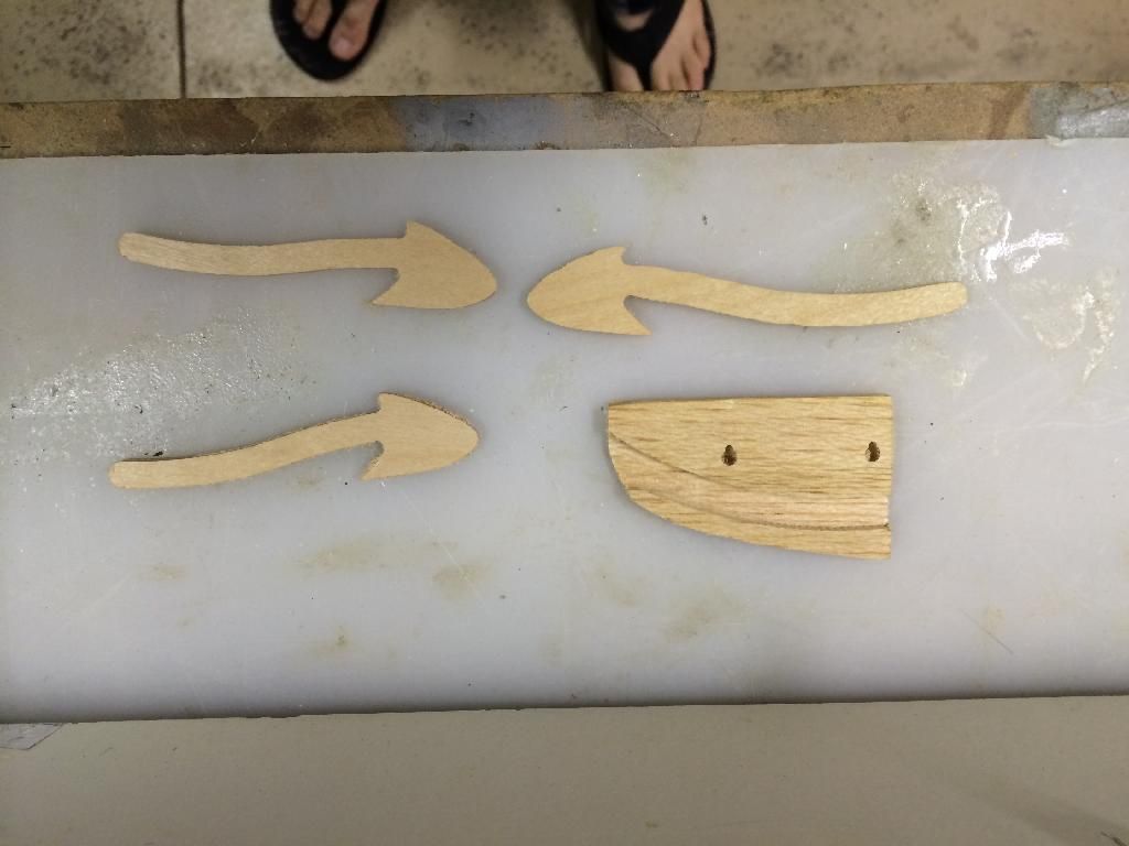
Heres a picture of it mocked up to the first wing panel:
The spoiler is actually slightly oversize on the front edge, reason being, the spoiler outlines were a PAIN to mold, so the perimeter of the wing isnt the best. So the spoilers are used to mark the trim line on the wing panel to adjust the wing edge to fit the panels perfectly.
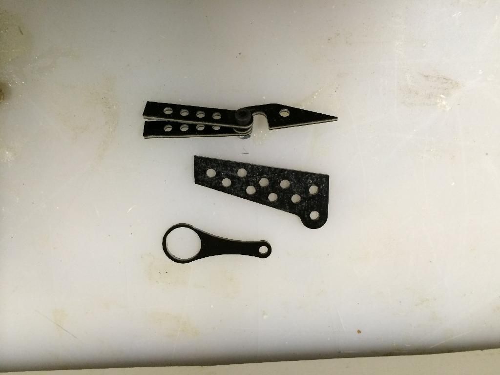
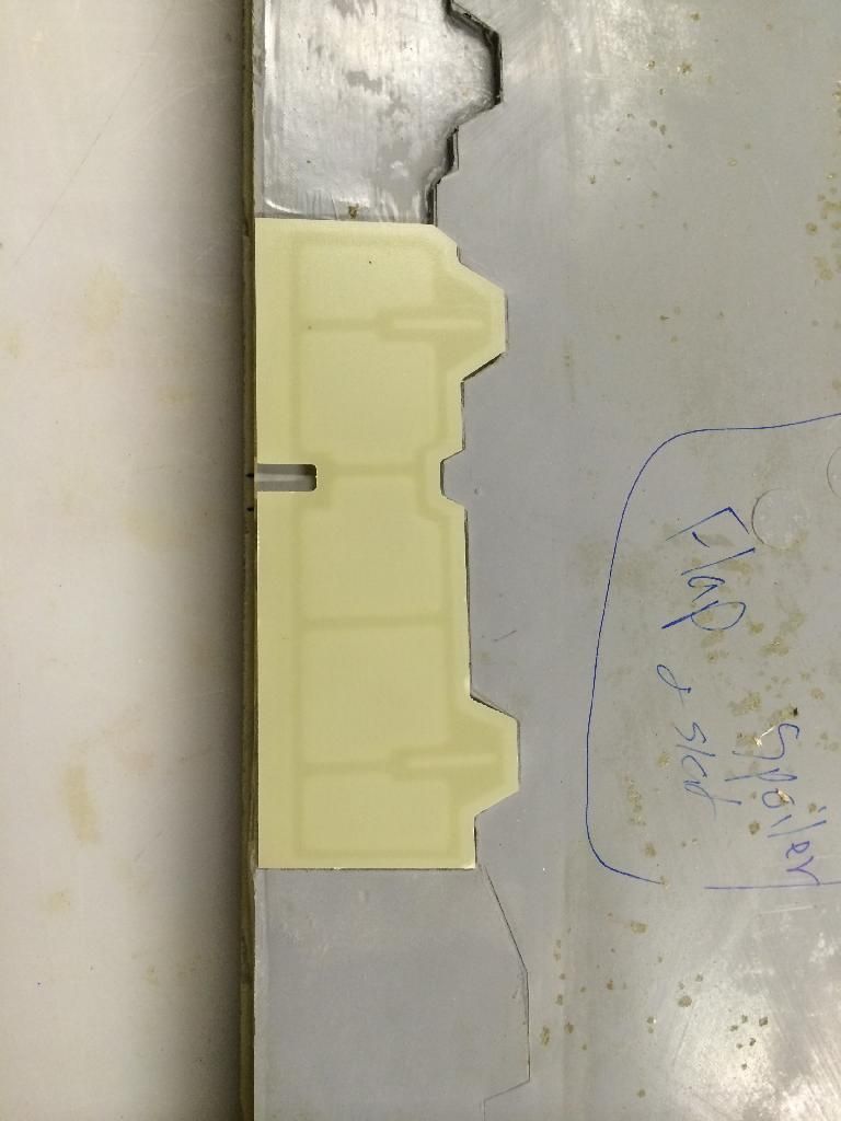
Heres a shot of the top of the spoiler with its hinges mocked in place.
Now your probably wondering what is up with the darker portion.
The spoiler panels are machined from .093" G10. The "skin" is approx. .035" thick. This appr. .058" thick difference is the structure on the back side of the panel. There are also premachined slots for the spoiler hinges to slot into with just enough gap on either side to allow hysol to fit in.
Overall weight for this panel is 16 grams. All four panels per wing are roughly the same area, so a full set of spoiler panels for one wing should be 64 grams or 2.2oz.
Once i get the basic airframe completed, ill go back into CAD and draw up the details that are seen on the underside of the spoilers and then machine the plugs for that. Those will then be a very lightweight fiberglass molding that will get glued to the Spoiler panels
Heres a picture of it mocked up to the first wing panel:

The spoiler is actually slightly oversize on the front edge, reason being, the spoiler outlines were a PAIN to mold, so the perimeter of the wing isnt the best. So the spoilers are used to mark the trim line on the wing panel to adjust the wing edge to fit the panels perfectly.
Heres a shot of the top of the spoiler with its hinges mocked in place.

Now your probably wondering what is up with the darker portion.
The spoiler panels are machined from .093" G10. The "skin" is approx. .035" thick. This appr. .058" thick difference is the structure on the back side of the panel. There are also premachined slots for the spoiler hinges to slot into with just enough gap on either side to allow hysol to fit in.
Overall weight for this panel is 16 grams. All four panels per wing are roughly the same area, so a full set of spoiler panels for one wing should be 64 grams or 2.2oz.
Once i get the basic airframe completed, ill go back into CAD and draw up the details that are seen on the underside of the spoilers and then machine the plugs for that. Those will then be a very lightweight fiberglass molding that will get glued to the Spoiler panels

 02-16-2014, 03:18 PM
#1342
Not much in the mood to mess with this thing today so I did some easy stuff.
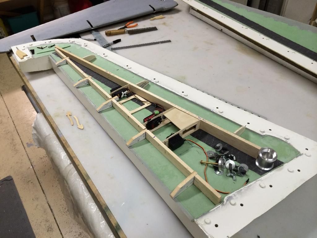
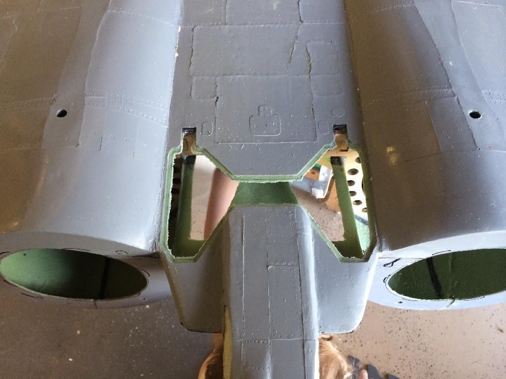
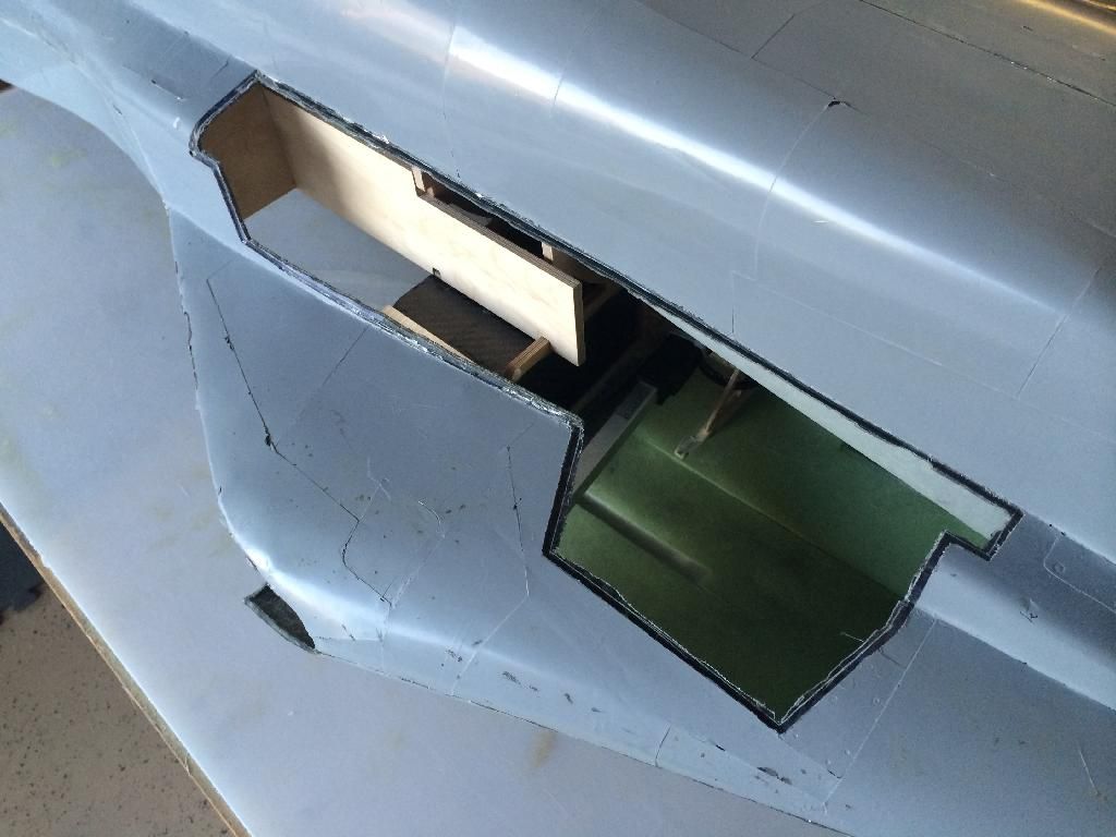
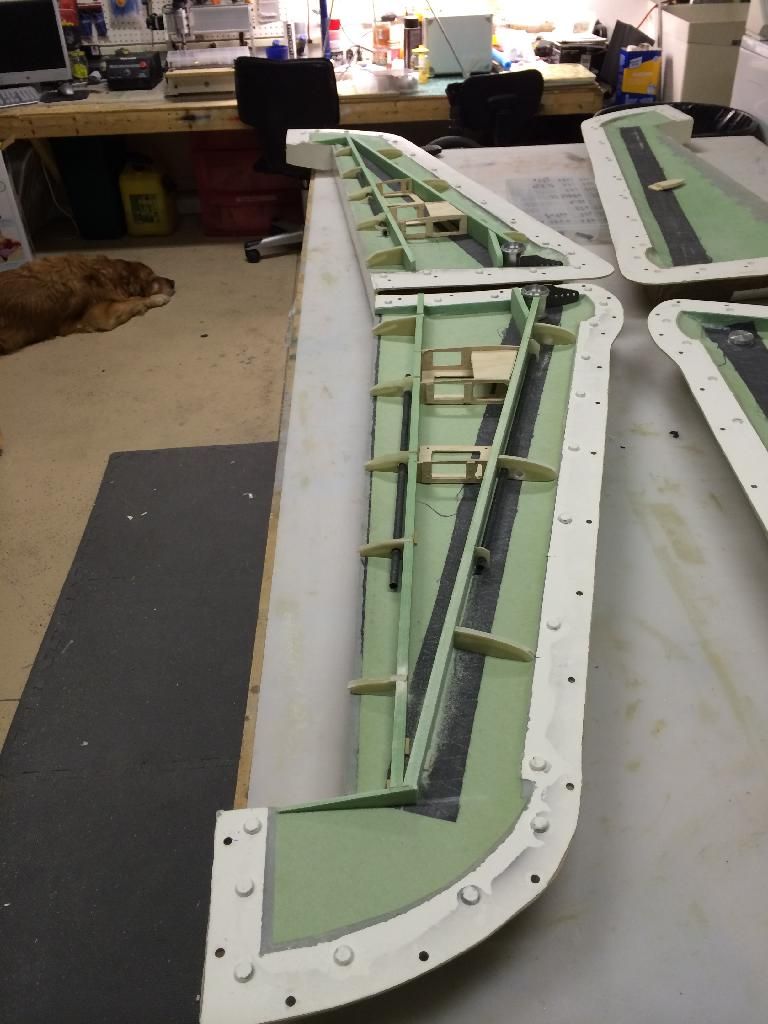
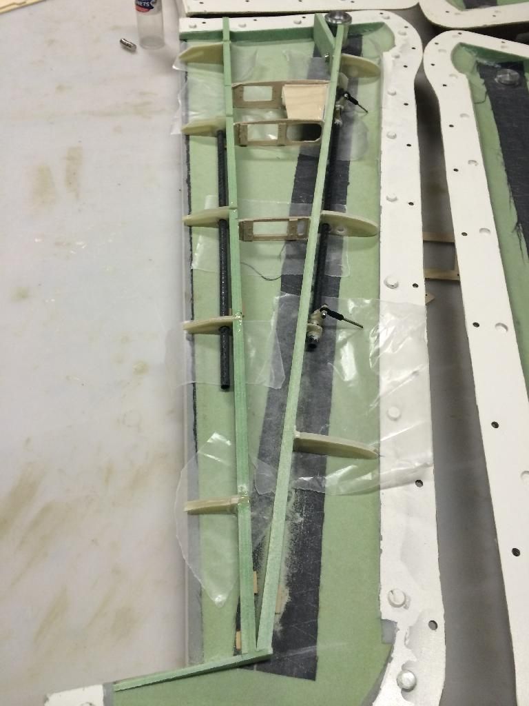
First i I cut out the speed brake and gear door areas leaving a lip around the perimeter. They are just rough cut now, so I still need to clean up the cuts and make it look pretty.. Err.... Professional. You can see in the photos the wing actuators are easily serviced through the wheel wells. Hopefully the tires don't attempt to occupy the same space. Lol
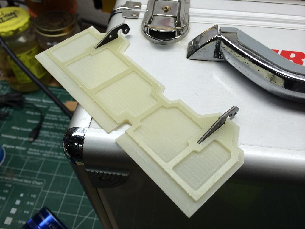
then I cut the carbon torque tube stock down for the left spoiler panels. I also mocked up the arms on the tube and the tube to the wing. The arms for the spoilers will need to be shortened slightly.
First i I cut out the speed brake and gear door areas leaving a lip around the perimeter. They are just rough cut now, so I still need to clean up the cuts and make it look pretty.. Err.... Professional. You can see in the photos the wing actuators are easily serviced through the wheel wells. Hopefully the tires don't attempt to occupy the same space. Lol
then I cut the carbon torque tube stock down for the left spoiler panels. I also mocked up the arms on the tube and the tube to the wing. The arms for the spoilers will need to be shortened slightly.
02-23-2014, 05:20 PM
#1343
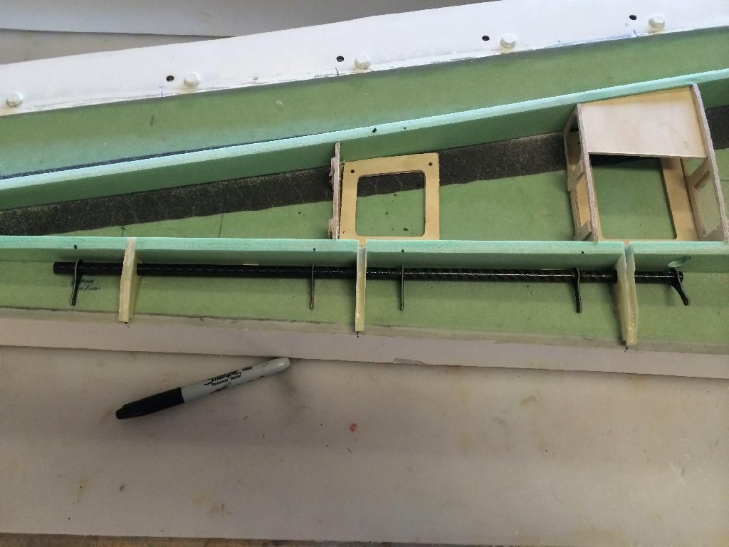
Finished up the remainder of the left wings internals. Its essentially ready to have all the parts hysoled to the spars and then i can close up the left wing. But first, im going to get the right wings internals positioned and tack glued all together so i can close up both wings at the same time.
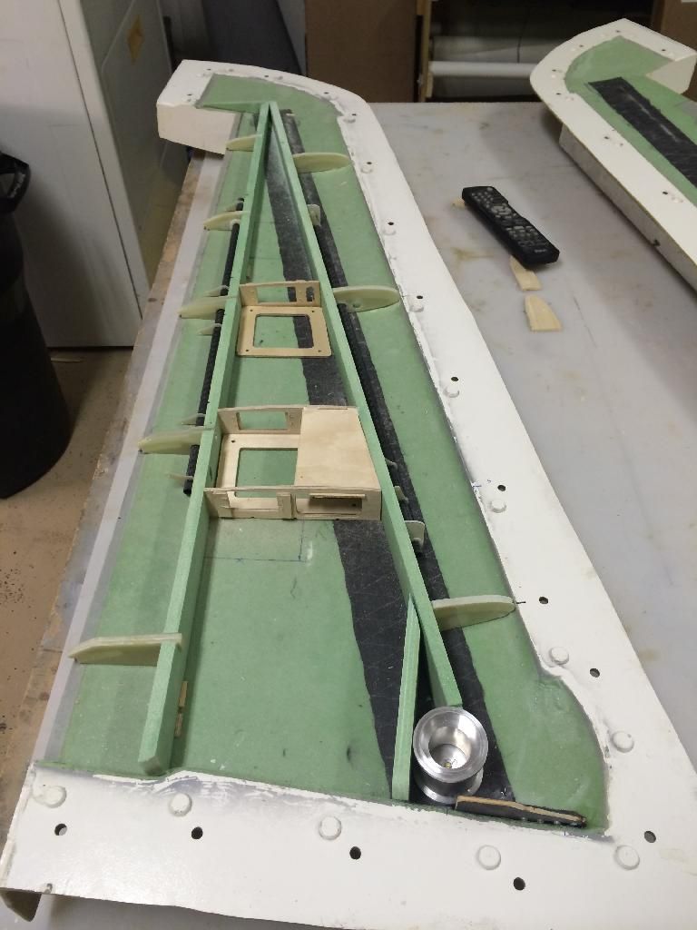
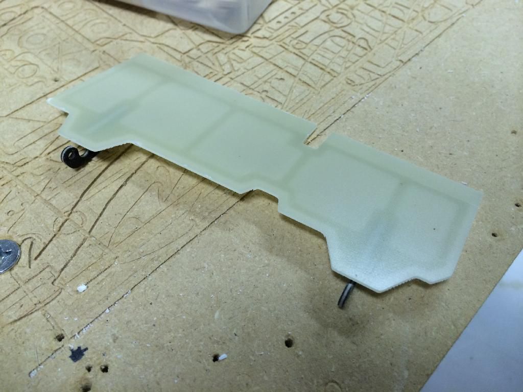
Slat torque tube:
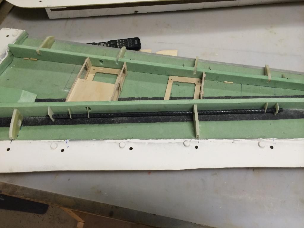
Spoiler torque tube:
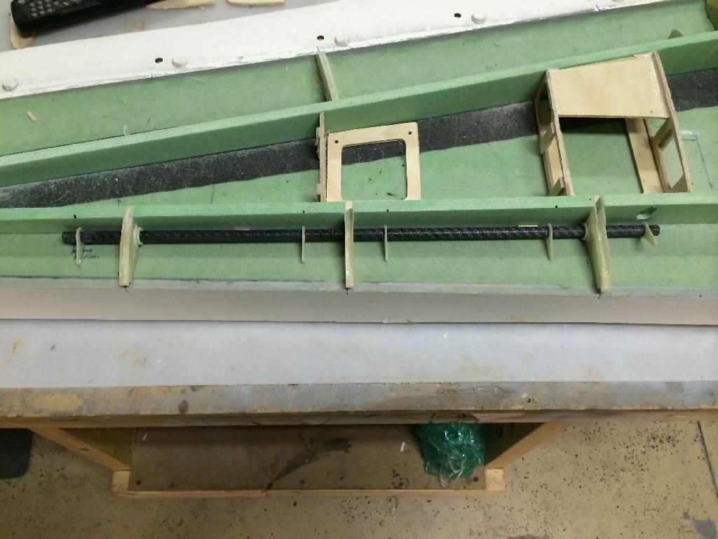
Internals removed from the wing:
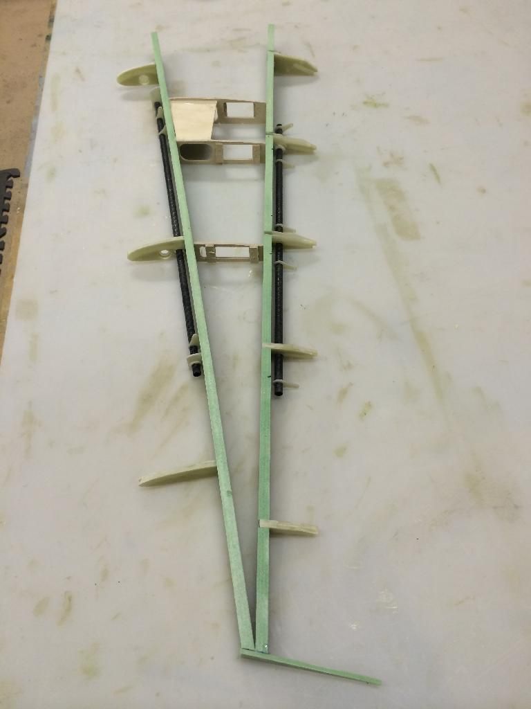

Slat torque tube:

Spoiler torque tube:

Internals removed from the wing:
 02-23-2014, 09:44 PM
#1345
So what do you do when the boss man calls saying take a paid day off..
WORK ON PLANES OF COURSE!
So the right wing internals are all tack glued together. I have to cut out some more torque tube arms cause i ran out of G10, luckily i have some 1/16" dragon plate that should work just fine. I need to get more ball links to.
I also have to make an install diagram of the internals so all future builds are as quick as the right wing. It took 2 1/2 months to so the left wing. It took 20 minutes to do the right! Lol
 02-24-2014, 06:17 AM
#1346
Junior Member
Join Date: Feb 2014
Posts: 4
Likes: 0
Received 0 Likes
on
0 Posts
Your attention to detail is phenomenal. I'd like to ask you for some advice in the future when I get to turn this into a plug. This is my first build and I'm no expert in this hobbie. Keep up the Awesome build and this bird should only be built in America!
Dwayne

Dwayne
02-24-2014, 05:11 PM
#1348
All of the internals and the slat torque tubes are Hysol'd together. Ill leave it till tomorrow to cure.
All that is left to do prior to closing the molds is to hysol the pivot bracket attach plate in place ( i would of done that tonight, but i ran out of 6-32 blind nuts) and hysol the hatch doublers to the lower wing skin. Ill do this stuff tomorrow.

All that is left to do prior to closing the molds is to hysol the pivot bracket attach plate in place ( i would of done that tonight, but i ran out of 6-32 blind nuts) and hysol the hatch doublers to the lower wing skin. Ill do this stuff tomorrow.


