


SE5a alignment problems
 01-22-2014 | 12:30 AM
#51

Thread Starter

Thanks, Jack. When I started building the kit, the intended purpose was to have a nice scale "everyday" flyer and to build as quickly as possible. Well, I did finish in 8 months, which is fast for me...but there are just so many fascinating scale features on an SE5a just screaming to be modeled (lacing, riveted metal panels, aldus sight, etc.) that I just couldn't resist.
On your question, I'm not sure. It may be that the unequal dihedral resulted from my attempts to "pull up" the leading edge with the forward landing wire. I plan to remove the port wires one at a time and see if I can straighten things out with a minimum of effort.
On your question, I'm not sure. It may be that the unequal dihedral resulted from my attempts to "pull up" the leading edge with the forward landing wire. I plan to remove the port wires one at a time and see if I can straighten things out with a minimum of effort.
 01-22-2014 | 06:29 AM
#52

My Feedback: (7)
Joined: Apr 2004
Posts: 235
Likes: 0
Received 0 Likes
on
0 Posts
From: Faribault,
MN
You are welcome I know what you me about not being able to resist doing up the scale features. I decided I wanted a simple scale plane and bought a seagul PT 19 arf thinking I could throw it together in a few weeks and have an everyday scale model to fly....well 6 months later with all the covering removed, paint scheme changed , wing sheeted instead of having open bays, new ailerons, rudder elevator,... ect ect.. it was complete.....and that's just the way it is.
01-22-2014 | 09:48 AM
#53
Thread Starter
It's oddly satisfying to have the top wing panels off. At least now I can start to fix the problems. The first task is to get the center section seated properly.
01-22-2014 | 02:02 PM
#54
Senior Member
01-22-2014 | 05:38 PM
#55
Thread Starter
Jack, a coupld of years ago I was ready to buy a Seagull Spacewalker II and bash it into something like a Czech Avia BH but at that time the Japanese supplier didn't have any in stock. In general, my feeling on bashing is that it typically doesn't take more than a month or so to frame up a simple model and it can take almost as long to strip and refurbish an ARF...so what's the point. That said, your PT-19 is a beauty!
I sure am tempted to build another Flair Puppeteer since I had so much fun flying and learning with that model (my first ever biplane). But by the time I'd get another kit to Japan it'd cost over $300 for a "fun-scale" model. I figure I just need to move on and build and fly scale only.
*****
But you know, if I couldn't do RC scale or had to downsize my expenditures, I would definitely be happy with scale free flight. Those guys have some serious skills!
Last edited by abufletcher; 01-22-2014 at 10:01 PM.
01-22-2014 | 09:52 PM
#57
Thread Starter
That's exactly the conclusion I come to every time I feel weak and think about ordering either a semi-scale kit or an ARF. I have the Dave Boddington plans for a really nicely scale 1/5 Pup based directly on the Replicraft drawings. I've also blown the plans up to 1/4 scale.
The Flair Puppeteer kit is currently selling for 147 pounds. That works out to a bit over $240 dollars, not including shipping.
http://www.stevewebb.co.uk/index.php...+of+Flair+Kits
The Flair Puppeteer kit is currently selling for 147 pounds. That works out to a bit over $240 dollars, not including shipping.
http://www.stevewebb.co.uk/index.php...+of+Flair+Kits
Last edited by abufletcher; 01-22-2014 at 10:01 PM.
01-23-2014 | 06:50 AM
#59
 01-23-2014 | 07:06 AM
#60
Thread Starter
Rigging instructions for the 1:1 size. http://www.foundation3d.com/forums/s...ead.php?t=2545
The Wylam drawings show the lower wing incidence to be 6 degrees with the top wing at 5 degrees. Interesting. The stab was apparently also at 5 degrees. The model wing incidence is also about 5 degrees but the stab is only at 3 degrees. But as I said, all that is built into the model and is pretty much unchangeable. What I can adjust is the dihedral and the incidence of the wingtips.
No washout.
Last edited by abufletcher; 01-23-2014 at 07:18 AM.
01-23-2014 | 07:11 AM
#61
My Feedback: (7)
Joined: Apr 2004
Posts: 235
Likes: 0
Received 0 Likes
on
0 Posts
From: Faribault,
MN
I agree about bashing another ARF. I don't think I would do another one unless I found one assembled and it was on the curb marked free.. The only advantage to bashing an ARF is that you get a jig built airframe that is light and straight. The project I am just starting is a 1/5th scale Boeing P12 C/D. The working plans are finished and I have atarted the molds for the corrigated metal componets...I am thinking over a year to complete. I have an original TF SE5a that I picked up for 10 US dollars on a fluke. It came with machine guns and pilot so was a great deal. After seeing how nice yours turnind out I have decided it deserves to be built someday. I have looked through it and it is a nice kit for shure.
01-23-2014 | 07:40 AM
#62
My Feedback: (7)
Joined: Apr 2004
Posts: 235
Likes: 0
Received 0 Likes
on
0 Posts
From: Faribault,
MN
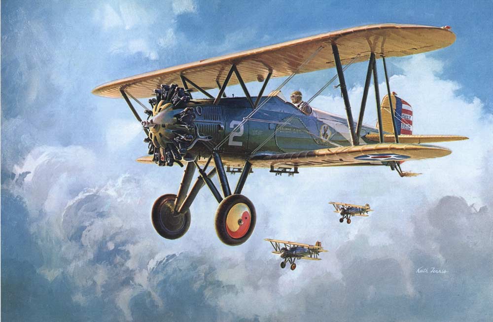
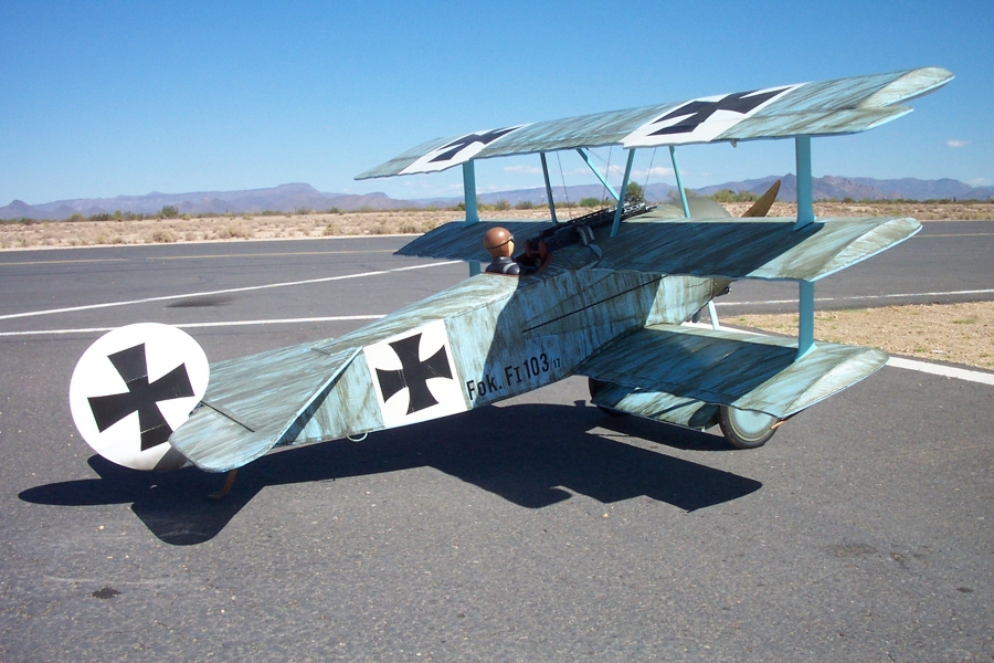
I have heard of incidences being set like that on a biplane where the top wing is slightly negative to the bottom wing. I set up a scratch built Fokker triplane in that manner and it flew perfectly The unrelaible reasoning for this that I was told was the top wing would stall after the bottom wing and the stall would be more stable...kind of makes sense....maybe? In looking through my plans for the TF Se5 it would seem impossible to get the engine thrust line off. Here is a photo of that Triplane that flies so well and it really does or did fly very very well. I sold it to a hobby shop owner in atlanta so I don't know if it is still with us or not.
01-23-2014 | 09:15 AM
#63
Thread Starter
The first pair of rigging wires are in place. These are the shorter of the two incidence wires that will form an X between the struts. I propped the model up so that the root wing incidence (unalterable) was at 0. (With the engine center line at 0 the wing root sits at about 5 degrees.) Then I prepared music wires that pulled the outer (lower) wing to 0 as well. This one wire goes a long way towards locking in the incidence. The second cross-bracing wire, just makes it more sturdy.
Afterwards, I checked the incidence on the top wing and it was (as expected) also 0 at the root, but came out as 1 on the outer wing, i.e. the outer wing has a 1 degree greater AofA then the root. The solution here might be to place some small washers between the brackets on the rear strut and the wing under-surface.
*****
The P12 is a great looking aircraft. I would be sorely tempted to make those louvered panels...and in fact ALL of the panels...out of lithoplate however.
Last edited by abufletcher; 01-23-2014 at 10:46 AM.
01-23-2014 | 09:24 AM
#64
My Feedback: (34)
I will sell you my 1/3 BUSA Pup kit, with aluminum cowl and Dubro wheels for $250. Go Big. I have an extra as I found a partially built one I'm rehabing.
As to your slight stab tilt. think back to Free Flight days and which way will it roll on take-off? I was taught look from behind the airplane.the airplane will want to roll to make the stab level. Thus with your SE-5A, georgous by the way, you should expect a slight roll to starboard as elevator rolls to level flight. Judging by small amount if your port stab lower, this is easily trimmed out with ailerons, but that is also speed dependent. Since you stated plane rolled left, you have a twist somewhere overpowering the stab effect.
You are doing what is needed, the rigging drill as so many have advised. We all want to see this baby fly!!
One last thought from Lou Proctor: if the plane flies "unmanageable" and all the wings are straight, try 2 degrees of down thrust. This made his N-28 a total ***** cat and blast to fly per 1984 review article.
01-23-2014 | 11:09 AM
#65
Thread Starter
01-24-2014 | 12:01 AM
#67
Thread Starter
Frustrating rigging mysteries. The lower starboard wing is leveled at 0 degrees at the root (incidence fixed by the winglets) and is 0 degrees at the struts (incidence set with a wire). Good so far. The upper starboard wing is also 0 degrees at the root (fixed by the center section) but comes in at -1 at the struts...so with 1 degree of washout. I'd really rather eliminate this but can't quite figure out how. It looks like lengthening the rear strut about 3-4mm might do it. But I could live with the -1 (on the meter) of washout, i.e. TE is +1 relative to the LE. Relative to the engine thrust line/aircraft center line this is +5 at the root and +4 at the struts.
OK. Now what about the port wing? The lower port wing root is also at 0 degrees and 0 degrees at the struts (with the incidence wire in place). But now what about the upper wing? It's 0 degrees at the root...but -2 at the struts. Where's that extra degree coming from? I measured the length of the struts+brackets (i.e. top of lower wing to bottom of upper wing) both front and back and the lengths are the same. So where's that extra degree coming from and how can I get rid of it?
From our discussions so far, it seems like that extra degree on the left side (essentially working like left aileron) might cause just the sort of left-pull it's experiencing.
Last edited by abufletcher; 01-24-2014 at 12:04 AM.
01-24-2014 | 04:12 AM
#68
Thread Starter
01-24-2014 | 04:50 AM
#69
Senior Member
You can't change the struts but you can shim where the wing connects to the strut! You probably have some 'cumulative' discrepancies accounting for the incidence differences. Most likely the strut attach points aren't uniform.
01-24-2014 | 05:46 AM
#70
Thread Starter
But that's the thing, I measured from surface to surface (wing gap along the line of the struts) so any discrepancies in strut length or attachment points wouldn't matter. It's also a bit surprising that the rear strut would need to be raised 3-4mm to correct the 1 degree difference.
But I'm sure you're right that it's probably a number of tiny misalignments that are adding up.
*****
So disregarding any prior length measurements, I took the practical approach of "try it and see." I added two M2 nuts under the bottom of the rear port strut (in effect lengthening the strut by 4mm). And I cut off the previous incidence wire. Took new measurements with the incidence meter which showed 0 on both top and bottom. Finally added a new incidence wire (with minimal tension). So I've finally got 0-0 on both bottom and top wings...even if those nuts aren't very attractive. At this point, I don't care. I suppose I could slap some black paint on them.
Last edited by abufletcher; 01-24-2014 at 06:40 AM.
01-24-2014 | 08:03 AM
#71
Thread Starter
Right...so with the addition of two M2 nuts under the starboard strut and two M2 nuts under the port strut in addition to two M2 nuts above it, the incidence of both wings, with all the strut cross-bracing ("incidence") wires in place, stands at 0-0 at the roots and 0-0 at the struts.
Now if I can just manage to do the flying and landing wires without messing up the incidence again. I've accepted that I'm going to use non-scale clevises to make the adjustments.
Now if I can just manage to do the flying and landing wires without messing up the incidence again. I've accepted that I'm going to use non-scale clevises to make the adjustments.
01-24-2014 | 09:04 AM
#72
My Feedback: (34)
Your patience and diligence will pay off.

I too have spent 2 days finalizing the rigging on my Pup. 3 wings are perfect; 1 still out of kilter.
Q: Did you ever finish the Sopwith Triplane?
P.S. I love your Snipe build thread. spend a few days reading it. Ashame that CD Designs no longer kits available. I may order the Replicraft plans from Jim Kiger this weekend for my future build.
01-24-2014 | 09:14 AM
#73
Thread Starter
I didn't get any further on a Sopwith Triplane than completing a 1/4 scale cowl (based on the Replicraft plans). The more I thought about it, the more it seemed like the Seidel 770 might be overkill for a 1/4 scale tripe hound and that maybe it would be better suited to a Strutter. Not so much in terms of power but in terms of weight in the nose. So I started working on the Strutter. The tripe is definitely more appealing to me. The Strutter is a bit of a Plain Jane.
So many projects and no clear order for which I'll get back to or when. For the immediate future the goal is to get the SE5a flying again, then finish up my CI. Then I really do need to get the Seidel up in the air.
So many projects and no clear order for which I'll get back to or when. For the immediate future the goal is to get the SE5a flying again, then finish up my CI. Then I really do need to get the Seidel up in the air.
01-24-2014 | 10:05 AM
#74
Thread Starter
Rear landing wires are done establishing a 5 degree dihedral on both sides...incidences are still the same. I used clevises and 256 threaded couplers on the bottom end of the wires.
01-24-2014 | 11:55 AM
#75
I re-engined my SE5a last year for more power but never got around to flying it. I might have to return to it. You need to get your SE5a flying to return to the Strutter; They have been moving again on RCSB and yours is not one of them. Did you check the scratch 1/3 Tripe being built over there?

