


SE5a alignment problems
 01-24-2014 | 12:26 PM
#76

Thread Starter

Yeah, that Tripe is really something. Almost depressing though, because anything I would do would unquestionably be less. Most recently, I've been working on my CI on RCSB. After struggling with the metal work for the nose cowl, I'm taking a little breather with the SE5. But soon I'll be back at work on the CI on my main bench and get the Strutter (or maybe even the MR Strutter) on the second bench.
*****
Now, finished with the forward landing wires and also got the rear (doubled) flying wires back on. Incidence and dihedral still looking good. Tomorrow I'll attach the forward sets. And then the mid-span flying wires. And after that I need to redo the elevator wires because it's clear now that the stab isn't level.
Last edited by abufletcher; 01-24-2014 at 12:29 PM.
 01-24-2014 | 01:22 PM
#77

My Feedback: (34)
ABU, I spoke with a club buddy who fly's 1/4 scale BUSA SE-5A. I know not the same as yours but his wing and stab incidences are very close to yours. He said this allows the plane to fly in a "nose down attitude" just like the real one. that said I would recommend not changing engine down thrust to -2 degrees as I mentioned earlier. The plane will naturally settle a bit nose down in flight. attached pic is his. 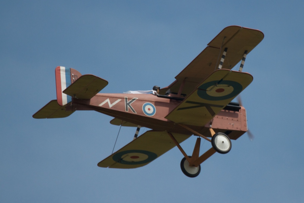
01-24-2014 | 05:33 PM
#81
Senior Member
Multi-wing alignment is interesting to say the least! One thing I picture in my mind is the downwash of airflow trailing a wing. Associated with that is an upwash at the LE of wing. A multi-winged airplane needs to have all the wings aligned with the airflow going over and around them. If the wings have no stagger then the wings can 'make do' with no need for differences in incidence. You can visualize that a fwd stagger will cause the need to have the lower wing(s) aligned with air that is moving downwards as well as backwards relative to the upper wing(s). Vice versa for the negative staggered jobs. The effect is to make the wings stall as a unit. What we are attempting to do is actually have all the wings' lift be equal. This only works for one 'ideal' airspeed because the air is compressible and the 'alignments' change with speed.
I have a Top Flite SE5 that I'm thinking of building very soon. I built one >20 years ago. It was a great flying machine! This one will get a full set of fittings from Joe at Proctor in lieu of those goofy 'z' bend rigging wires. I bought some 'Smooth-on.com' rubber compound for making 'tyres' in dull white so that'll make it even better! I'll experiment making the 'beach ball' tires for my scratch build Vampyr sailplane. You can find it on RCAerotowing.com site. Keep up the great work on you Albi two-holer!
I have a Top Flite SE5 that I'm thinking of building very soon. I built one >20 years ago. It was a great flying machine! This one will get a full set of fittings from Joe at Proctor in lieu of those goofy 'z' bend rigging wires. I bought some 'Smooth-on.com' rubber compound for making 'tyres' in dull white so that'll make it even better! I'll experiment making the 'beach ball' tires for my scratch build Vampyr sailplane. You can find it on RCAerotowing.com site. Keep up the great work on you Albi two-holer!
01-24-2014 | 06:33 PM
#82
Thread Starter
No. like Teus's EIII, that Tripe is pretty much the Tripe to end all Tripes. I mean, if you replicate every single thing on the Replicraft plans and do each perfectly, what else is there to do?
Last edited by abufletcher; 01-24-2014 at 07:38 PM.
01-24-2014 | 07:37 PM
#83
Thread Starter
All the wing wires are back in place...and ASAP/CEGE. If there's any "twisting" remaining, it's just going to have to stay there. Now for the stab...which also confuses me. The wing center section has been carefully set level (spanwise) relative to the building table. And the wings panels have precisely 5 degrees of dihedral. So the the wings are "level."
And placing the angle meter on the stab halves show them also to be completely level. Great.
Soooooooooooooooooooo...why does the stab not look level when sighted with the wings???
And placing the angle meter on the stab halves show them also to be completely level. Great.
Soooooooooooooooooooo...why does the stab not look level when sighted with the wings???
01-24-2014 | 08:21 PM
#84
With apologies to the builder, I see "flaws" in the Tripe. It is missing some delicate details. Im not there yet, so it is a jerk statement. Remember Peter McDurmott was World champ with a Tripe in '92.
01-24-2014 | 08:57 PM
#85
Thread Starter
I guess I haven't looked that closely. And yeah, I do remember Pete's Tripe...I wonder how much he replicates in the "inside" stuff. For my money, he's the Master of WWI scale.
*****
In this new (rear) photo of the SE5a, the alignment of the stab isn't so far off...perhaps just half a degree or so, which I can easily correct with the wires. Maybe it was some kind of optical illusion going on before. There's also a slight twist to the elevator halves.
*****
In this new (rear) photo of the SE5a, the alignment of the stab isn't so far off...perhaps just half a degree or so, which I can easily correct with the wires. Maybe it was some kind of optical illusion going on before. There's also a slight twist to the elevator halves.
01-25-2014 | 12:43 AM
#86
I may be completely talking through my hat here, but reading this thread a few questions come to mind and they just keep on nagging me.
1. Did you have a similar issue with the Snipe? The SE5a SHOULD be a much more stable platform and much easier to fly than the Snipe. It's much longer coupled after all and has more dihedral...
2. I have seen Bipes with MUCH less care taken with setup (in the wings at least) fly just fine. A friends Mick Reeves Pup for instance has a massive warp in the lower port wing and he is able to fly it quite adequately with only a trim change.
The idea that keeps nagging me is that it MUST surely be Engine thrust angle that is the issue.
Cheers,
Hugh
01-25-2014 | 01:56 AM
#87
Thread Starter
Still a few more tail wires to go, but the stab now appears level.
I didn't have this severe left turn problem with the Snipe. But I just can't see any left thrust on the engine AT ALL. It appears to be 0-0 with the fuselage center line.
It may be a combination of things. It may be, as people have suggested, that the ailerons on the SE5a are almost ineffectual. It may be that the rudder wasn't quite straight. It may be that the elevator wasn't quite level. And it may have been that I wasn't using much rudder during my flights. And it may have been that my nerves just weren't very steady.
But I feel you are right that all of these maybes shouldn't have added up to such a challenging flight. As you say, SE5a models are suppose to be easy flyers.
I'll look again, but unless I'm going blind, I just can't see any.
2. I have seen Bipes with MUCH less care taken with setup (in the wings at least) fly just fine. A friends Mick Reeves Pup for instance has a massive warp in the lower port wing and he is able to fly it quite adequately with only a trim change.
But I feel you are right that all of these maybes shouldn't have added up to such a challenging flight. As you say, SE5a models are suppose to be easy flyers.
The idea that keeps nagging me is that it MUST surely be Engine thrust angle that is the issue.
01-25-2014 | 02:03 AM
#88
Thread Starter
I'll add that since my last flight with the SE5a I did a lot of "rudder" practice with the Puppeteer. I'd fly it almost as if it were a 3-channel model and was surprised that ailerons aren't all that necessary. You have to think ahead a bit more and allow for more time, for example, to level the wings after a turn. You also get used to the different way that the model responds to right rudder vs. left rudder (on the Puppeteer, left rudder also caused it to dive left) while right rudder would mostly just scoot the tail around to the right.
01-25-2014 | 07:01 AM
#92
Senior Member
Looks great! Really makes me want to put mine on the board, like... now! I sure don't need to start another project until some get out of the way! As others state: the longer the nose then the less right thrust is needed. Similar thing holds true for changing thrust up or down. High wing needs down thrust and a low wing could use up thrust. Average multiwingers thru thrust line to get starting points. Flight envelope experimentation determines what is desired.
01-25-2014 | 07:39 AM
#93
Thread Starter
01-25-2014 | 06:22 PM
#94
My Feedback: (34)
Abu, being 1/2 a world away its hard to communicate. Your effort on alignment looks well within the normal ASAP idea. Cool.
But I see MerlinV's point.
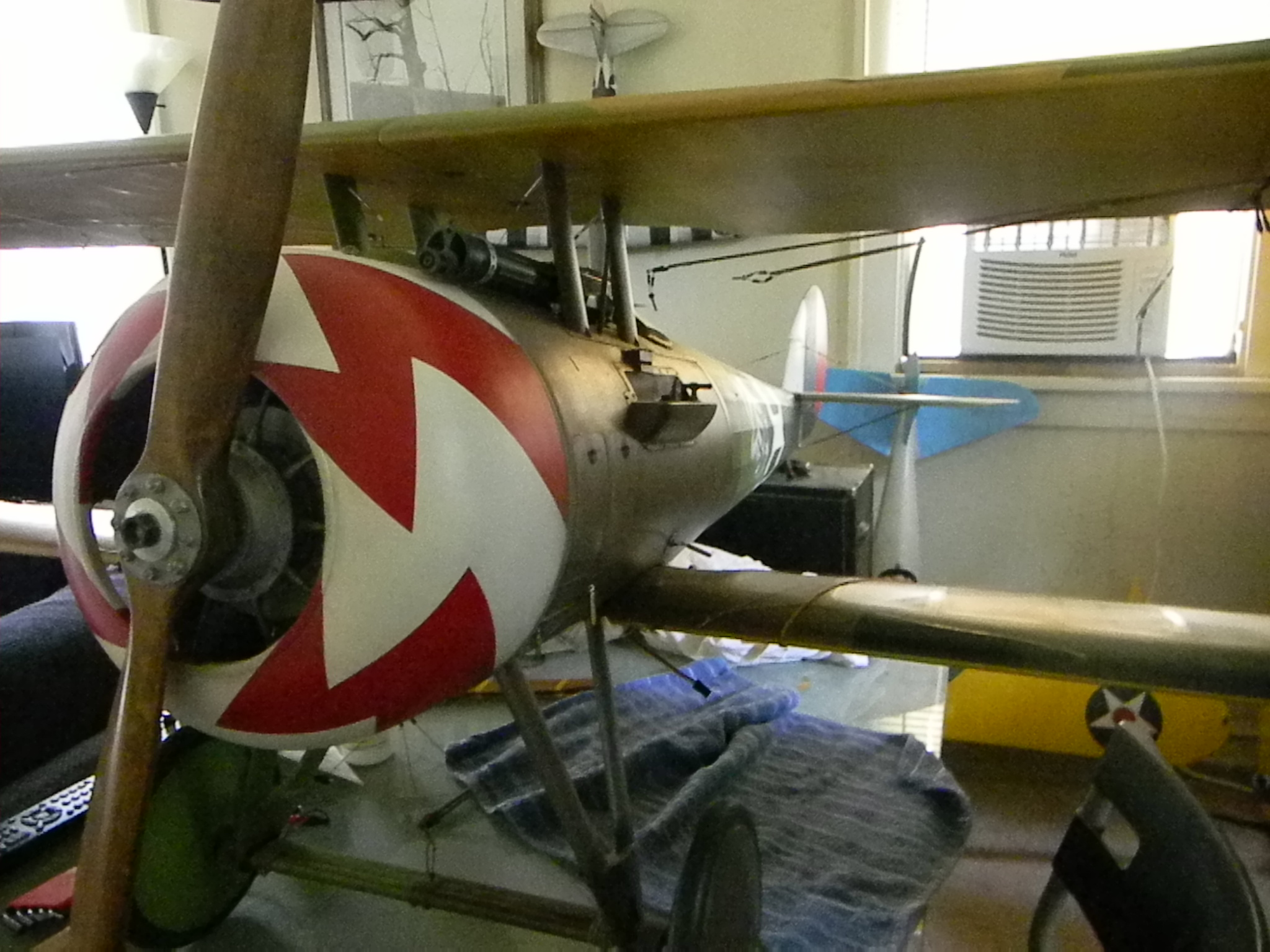
When I pull-up the engine picture and ran it on the edge of my laptop frame, your port side prop was slightly more aft. That would be left thrust and very bad.
a picture check is not good enough. This will only takes five minutes to check.
Get a piece of string, that will not stretch, and measure from rudder post to the prop tip. Mark it. Turn prop 1/2 turn for comparison. ( prop trueness). Now measure starboard side and do a 1/2 turn check too, to compare the marks. Your starboard prop side needs to be shorter. I'd say about 1/8 th to 3/16 th ( less than 1cm) or something about in that range.
It is just like checking the wings for squareness to the fuse. She is a great looking plane. Good luck on the re-maiden.
But I see MerlinV's point.
When I pull-up the engine picture and ran it on the edge of my laptop frame, your port side prop was slightly more aft. That would be left thrust and very bad.
a picture check is not good enough. This will only takes five minutes to check.
Get a piece of string, that will not stretch, and measure from rudder post to the prop tip. Mark it. Turn prop 1/2 turn for comparison. ( prop trueness). Now measure starboard side and do a 1/2 turn check too, to compare the marks. Your starboard prop side needs to be shorter. I'd say about 1/8 th to 3/16 th ( less than 1cm) or something about in that range.
It is just like checking the wings for squareness to the fuse. She is a great looking plane. Good luck on the re-maiden.
Last edited by FireBee; 01-25-2014 at 06:27 PM. Reason: Typos
01-25-2014 | 06:27 PM
#95
My Feedback: (34)
Abu, being 1/2 a world away its hard to communicate. Your effort on alignment looks well within the normal ASAP idea. Cool.
But I see MerlinV's point.
When I pull-up the engine picture and ran it on the edge of my laptop frame, your port side prop was slightly more aft. That would be left thrust and very bad.
a picture check is not good enough. This will only take five minutes.
Get a piece of string, that will not stretch, and measure from rudder post to the prop tip. Mark it. Turn prop 1/2 turn for comparison. ( prop trueness). Now measure starboard side and do a 1/2 turn check too, to compare the marks. Your starboard prop side needs to be shorter. I'd say about 1/8 th to 3/16 th ( less than 1cm) or something about in that range.
It is just like checking the wings for squareness to the fuse. She is a great looking plane. Good luck on the re-maiden.
01-25-2014 | 07:15 PM
#96
Thread Starter
Thanks for that tip. I had been wondering how people check side thrust since you can't do it with the meter. I will check my model, but again it looks dead-on to my eye. Alignment in the photograph might be more due to an off-center camera and a wide-ish angle lens.
But I'll check.
But I'll check.
01-26-2014 | 06:47 AM
#97
Thread Starter
So...after checking with the "string method" (actually using a wire cable) I found that the left measurement was 2mm shorter than the right measurement. That means there was some small amount of left thrust.
To correct this I had to completely removed the engine, cut down some of the wood around the engine and enlarge (and file) the holes in the mounting platform. Now I've managed to get that 2mm shorter distance over on the right side (so a slight amount of right thrust).
The method that the model uses to mount the engine (beams with ply "shelves") is not new. And I think it's intended to make straight engine mounting fool-proof. Well, I certainly proved THAT wrong!
01-26-2014 | 07:41 AM
#98
Senior Member
You can use a straight edge bolted to the prop for these measurements, too! 'File' that for future use. My Robart incidence meter has a hole for mounting to the engine's prop drive. If I ever have any questions I just block fuse and check. Your 'transformation' is almost over so can't wait for the flight reports. Yes... 'reports'! Check your six and often!
01-26-2014 | 08:31 AM
#99
My Feedback: (7)
Joined: Apr 2004
Posts: 235
Likes: 0
Received 0 Likes
on
0 Posts
From: Faribault,
MN
I looks like you are there. It would be very difficult to get the engine out of alignment with the way dave Platt designed it's construction. Wouldn's the camera have to be perfectly square to the model to use a photo to find a misalignment using the edge of the photo ( edge of computer screen ) ? If the camera was even slightly off the engine would appear misaligned even if it is not. Measure on he model and call that correct. Have a great test flight ! It looks and sounds good to go.
01-26-2014 | 04:53 PM
#100
Thread Starter

