


TF FW190 GIANT ARF
 06-08-2013, 09:14 AM
#1826

Hi cubarican.,
According to the drawings on robarts site the only difference is tbe electric or air power to work the mechanism.
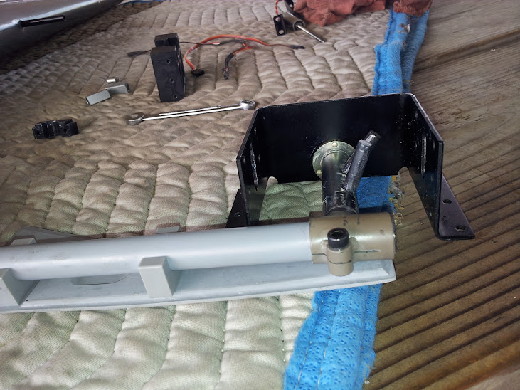
Here are a few images of what I intend to do. This might also work with the air version of these
retracts.
Since I was taking my left unit apart to restraighten the pin and heat treat it, I disassembled the right side also for the
purpose of heat treating its pins also.
While I was at it I used the right side housing to test my idea. And it worked GREAT.
The first image is tbe stock setup.
Edit:
Just looked at a picture of the mechanism of the air retracts for this plane from robart.
They do not use the same twin pin actuation system. If they are made in the same manner then I would have to guess
that the air system would be every bit as easy to bend the single drive pin as the electrics.
Seeing this I am happy I went with the electrics as that now allows me to acquire and install the additional parts so that
I can have the second pin share the loads.
According to the drawings on robarts site the only difference is tbe electric or air power to work the mechanism.
Here are a few images of what I intend to do. This might also work with the air version of these
retracts.
Since I was taking my left unit apart to restraighten the pin and heat treat it, I disassembled the right side also for the
purpose of heat treating its pins also.
While I was at it I used the right side housing to test my idea. And it worked GREAT.
The first image is tbe stock setup.
Edit:
Just looked at a picture of the mechanism of the air retracts for this plane from robart.
They do not use the same twin pin actuation system. If they are made in the same manner then I would have to guess
that the air system would be every bit as easy to bend the single drive pin as the electrics.
Seeing this I am happy I went with the electrics as that now allows me to acquire and install the additional parts so that
I can have the second pin share the loads.
 06-08-2013, 03:21 PM
#1829
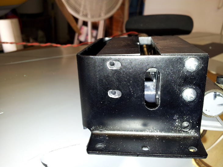
No I did not add any metal. I simply used the housing from the other
retract to test my idea. Study the pictures.
And yes you could use your receiver battery but I would recommend
against it. Robart makes it an option to plug in a battery just for the purpose
of powering the retracts. This is the best way to go as it provides a
margin of safety and allows you to add needed weight to the nose of the plane.
06-09-2013, 04:05 AM
#1830
Senior Member

ORIGINAL: cubarican323
Can you run them off your receiver battery of do you need to run a seperate battery for the retracts?
Can you run them off your receiver battery of do you need to run a seperate battery for the retracts?
I do not run the retracts off the Rx battery.
06-09-2013, 04:15 AM
#1831
Senior Member
ORIGINAL: Tommy_Gun
I submit, that if you were to properly locate and drill another Housing Assembly, PN# 2.3. The loads could be shared by both pin assemblies. I have searched your parts listing on your web page and was unable to find this part number listed.
Please contact me with price and availability of these parts. As I will be happy to undertake the modification and installation of these into my current units on my own.
Thank You,
Tom Richardi

I am very interested in this modification so keep us informed.
06-09-2013, 06:03 AM
#1832
SrTelemaster150 ,
I have already tested the fit of the second housing. Check the pictures I posted earlier on the previous page.
Once the second housing block is properly aligned, the actuating mechanism works just as good as the original setup, with the
bonus that now BOTH of the pins are sharing the load in the down and locked position.
However, the holes you mention do not fully line up for this purpose. It would require opening up the hole in the metal frame a little bit,
about half a hole, to allow the screw to go into the housing block.
06-15-2013, 04:42 PM
#1833

I flew my TF GS Corsair with my buddy that has the FW 190 today and it was a riot!
We took off and got situated, he was in the lead and I was going to follow. He has had 3-4 flights on his and Ive had 13-14 on mine. We both have the DLE 55RA. A couple laps around the field and we got in the groove. I was expecting him to go easy but in no time it was balls to the walls. We ended up doing some mock combat seeing who could stay on the others tail the longest and so on.
Here is how they stacked up;
Speed - the Corsair was faster in the dive. The two are even in level flight.
Climb - the FW has an advantage, the Corsair bleeds off energy faster.
Turn - they are pretty even but we didnt explore slower speeds and more technical flying. Just tried not to pull too much elevator and snap them out of the turn so we carried a lot of speed and full power but tried to turn tight. They are pretty even so its more about pilot than plane, so far.
Landing - the FW slows way down and can catch you out with a bad bounce if you dont handle the plane correctly. It will get into a bouncing sequence thats hard to fix so carrying a little speed on the mains works better most of the time. The Corsair is very solid all the way down to landing as well but you have to take care the flaps are very effective. Balance the plane on the power and keep it on power as it rolls out and its smooth. The Corsair seems easier to handle than the FW at this point but he needs more practice with it. I have not flown the FW yet.
The pair in the air tearing it up for 10min was a really good time. I hope the others guys get motivated to buy a big war bird so we can have 3 or 4 going at one time!
06-16-2013, 05:38 AM
#1835

Chris, formation/tandem flying with the scale planes is the only way I can do it without falling asleep. If Roberto and I are at the field, every flight with the wulfs is together, lots of fun. I really want to do formation with two Moki's. The sound would be awesome. He has a bearcat with a moki, mine (as you know) is with some crackhead in LA.... [ ]
]
]
06-16-2013, 07:32 PM
#1837

Join Date: Jul 2012
Location: litllerock,
CA
Posts: 38
Likes: 0
Received 0 Likes
on
0 Posts
Hello tommy gun I would really like to set my electric robarts for my FW just like you did can you please help me out? How did you heat treat it? Where did you get that extra piece you added on them?
06-16-2013, 08:13 PM
#1838
Hi cubarican,
I redid the heat treating by using a propane torch to heat each
pin individually to a cherry red state and then quenching the part
in mineral oil. As for the additional housing for the up/down lock.
Robart is sending another pair of those parts so that I can do a
permanent installation.
The previous pictures I posted were of me testing the idea as I had
both gear assemblies apart for repair.
Once I get the parts from robart I will be happy to post a step by step
account of what I do.
06-18-2013, 01:48 AM
#1840


Join Date: Jun 2009
Location: Melbourne, AUSTRALIA
Posts: 1,505
Received 0 Likes
on
0 Posts
Not quite on topic here.... but does Jack Devine still do FW190 kits?
Seeing as a TopFlite FW190 is proving hard to get/ridiculously expensive, I thought I might try one of his kits as an option.
Any advice?
BJ
Seeing as a TopFlite FW190 is proving hard to get/ridiculously expensive, I thought I might try one of his kits as an option.
Any advice?
BJ
06-18-2013, 06:00 AM
#1841
My Feedback: (2)
Join Date: Jul 2003
Location: Brisbane, QLD, AUSTRALIA
Posts: 2,787
Likes: 0
Received 8 Likes
on
4 Posts
ORIGINAL: BJ64
Not quite on topic here.... but does Jack Devine still do FW190 kits?
Seeing as a TopFlite FW190 is proving hard to get/ridiculously expensive, I thought I might try one of his kits as an option.
Any advice?
BJ
Not quite on topic here.... but does Jack Devine still do FW190 kits?
Seeing as a TopFlite FW190 is proving hard to get/ridiculously expensive, I thought I might try one of his kits as an option.
Any advice?
BJ
Last few guys who I read about trying to buy anything off him got burnt real hard....
06-18-2013, 07:19 AM
#1843

Hey BJ:
Take a look at Bob Holman's A-8 or D-9, both are 80" wingspan, they come with nice glass fuses, clear canopy and foam cores. They've been around for years and are excellent kits and flyers. I have both and they are well worth the money. You'll have to e-mail Bob as these are not in his catalogue. www.bhplans.com.
Cheers,
06-18-2013, 07:39 AM
#1844
My Feedback: (43)
ORIGINAL: Tommy_Gun
Hi cubarican,
I redid the heat treating by using a propane torch to heat each
pin individually to a cherry red state and then quenching the part
in mineral oil. As for the additional housing for the up/down lock.
Robart is sending another pair of those parts so that I can do a
permanent installation.
The previous pictures I posted were of me testing the idea as I had
both gear assemblies apart for repair.
Once I get the parts from robart I will be happy to post a step by step
account of what I do.
That is a great idea to use two of the blocks. I like this idea better than upgrading to the metal blocks.
06-19-2013, 02:41 AM
#1845
Join Date: Jun 2009
Location: Melbourne, AUSTRALIA
Posts: 1,505
Received 0 Likes
on
0 Posts
ORIGINAL: Duplicator41
Hey BJ:
Take a look at Bob Holman's A-8 ...
Hey BJ:
Take a look at Bob Holman's A-8 ...

Email sent

BJ
PS - no good. I can get a wing kit sent down here, but not a fuze - so it's back to square 1...[
]
06-23-2013, 07:28 PM
#1846
Join Date: Dec 2005
Location: Victoria,
MN
Posts: 3,934
Likes: 0
Received 0 Likes
on
0 Posts
ORIGINAL: Tommy_Gun
Could I talk one of you into posting a picture of the mechanism in your robart electric retracts?
The pin that carries the load of up and down lock in mine seems to bend on anything less than
a perfect landing roll out.
l'm considering installing a second cam block to the mechanism so that both pins share the loads.
Edit:
Nevermind, I found a stock photo of these units.
Look at the drive pin that is in the cam of the inside of the housing assembly.
This is all that is keeping the gear properly located during the down and locked position. As well as the up and locked position.
Obviously the loads in the up position do not come close to those in the down and locked slot.
Here is an email I just sent off to robart from their online contact form.
Dear Sirs,
I had called and sent pictures in on 6/7/13 regarding the ease with which the actuating pin on the trunion was bending on the electric gear for my giant Top Flite FW190.
The pin I refer to is the only load bearing point to keep the gear in the correct angular relationship to the design of the aircraft. This design is too weak as evidenced by the ease with which it bent when at the end of a landing roll out the strut was side loaded as I fought a cross wind to stay on the runway.
I submit, that if you were to properly locate and drill another Housing Assembly, PN# 2.3. The loads could be shared by both pin assemblies. I have searched your parts listing on your web page and was unable to find this part number listed.
Please contact me with price and availability of these parts. As I will be happy to undertake the modification and installation of these into my current units on my own.
Thank You,
Tom Richardi
That is a fantastic idea!!!...
This could be applied to ALL of the Robart gear... Including my TF giant p51 great as well...
Only question is, Does it make any dif in side loads??
I can only guess that Robart will come back and say:
"The single pin setup, is made so that it will give and break the plastic, and pin, instead of the retract ripping of the wing"
I would come to say:
"If the plane is built right, you don't want you retracts to bend, or break, when you land in a crosswind, or have to turn the plane abruptly on rollout."
06-24-2013, 07:26 AM
#1847
Great news!
The upgrade works like a charm.
I spoke to Robart last Thursday and they overnighted a set of housings to me that I received on Friday.
Took about 1 hour to install the additional housings to each retract and then flew it for the first time on Saturday before our warbid race.
The difference in durability is amazing.
I flew the plane three times with less than perfect landings and had no issues at all.
I'll wpost a quick run thru with photos later.
EDIT:
I just posted a pair of videos on YouTube under the username topmenace. They show the gear mechanism going thru a cycle before and
after this upgrade.
 06-24-2013, 06:08 PM
#1849
Couldn't get the youtube link to work from my phone.
Try this.
This is the stock setup.
[youtube]http://www.youtube.com/watch?v=N0CWqf1_-fg[/youtube]
This is the same unit with the upgrade of adding the second housing.
[youtube]http://www.youtube.com/watch?v=ZiZfdVV2CyU[/youtube]
The upgrade process went smooth and easy.
You don't have to completely disassemble the retract unit.
1)After removing the retract from the wing, cycle the unit so that it is positioned at about mid travel.
2)Remove the two phillips head fasteners that hold the inside motor bracket from the retract unit. These have the only nuts on the inside of the unit.
3)Using a dremel CAREFULLY elongate the holes to allow the new housing holes to be used. Fit the housing into the frame as you go to see that you are
achieving the desired results. Do NOT shove the new housing hard up against the slider block. Just fit it into position in a straight square manner that will
allow the unit to work without binding.
4)Reassemble to retract unit with the new housing by reinstalling the retract motor bracket, the nuts are not needed as you now thread into the housing block.
You will need to get a pair of 4/40 screws about 1/4" long to install to the other side of the housing.
Apply a light grease film to the moving parts. I used white lithium grease.
Test the unit before reinstalling. There is a clamp piece that is retained by two countersunk screws. Don't over torque these as you can cause
excessive resistance that will slow the unit down.
Now if you side load the retracts hard enough to bend the pins, you have had a pretty ugly landing.
I know, I did it last Saturday when the engine bogged on me due to a crack in the fuel tank.
I landed her hard due to a desire to not have to do a go around and landed fast in our grass area with a quick turn to the left as the plane came to a stop.
The right strut got bent inward and it had no effect on the wing structure or gear mount rails.
Both pins were bent a bit to the same angle and it was an easy matter to remove the unit, straighten the pins and reassaemble/reinstall the retract.
Took all of about 30 minutes with me BS'ing with all the usual suspects.
Also, since I am using the Saito FG57T the CG was further forward than need be. It balanced on the factory indicated spot.
But I did the calculations myself directly on the wing and found the factory spot to be a little more than 1.5" ahead of where I calculated it should be.
Yes the plane flew well in that configuration, but I have since removed both ballast plates on the firewall and the plane has gotten even better in the flying and ground handling department.
I think that with the load of ballast off the nose the tailwheel is now better planted when the tail drops, giving me better control on the ground.
Here is an attempt at explaining the problem.

Here is an example.
Stock unit installed to wing.

Holes in frame elongated to pickup the holes in new housings. This was easily done in less than 3 minutes with a zip bit in a dremel.
Upgraded unit installed to wing.

Try this.
This is the stock setup.
[youtube]http://www.youtube.com/watch?v=N0CWqf1_-fg[/youtube]
This is the same unit with the upgrade of adding the second housing.
[youtube]http://www.youtube.com/watch?v=ZiZfdVV2CyU[/youtube]
The upgrade process went smooth and easy.
You don't have to completely disassemble the retract unit.
1)After removing the retract from the wing, cycle the unit so that it is positioned at about mid travel.
2)Remove the two phillips head fasteners that hold the inside motor bracket from the retract unit. These have the only nuts on the inside of the unit.
3)Using a dremel CAREFULLY elongate the holes to allow the new housing holes to be used. Fit the housing into the frame as you go to see that you are
achieving the desired results. Do NOT shove the new housing hard up against the slider block. Just fit it into position in a straight square manner that will
allow the unit to work without binding.
4)Reassemble to retract unit with the new housing by reinstalling the retract motor bracket, the nuts are not needed as you now thread into the housing block.
You will need to get a pair of 4/40 screws about 1/4" long to install to the other side of the housing.
Apply a light grease film to the moving parts. I used white lithium grease.
Test the unit before reinstalling. There is a clamp piece that is retained by two countersunk screws. Don't over torque these as you can cause
excessive resistance that will slow the unit down.
Now if you side load the retracts hard enough to bend the pins, you have had a pretty ugly landing.
I know, I did it last Saturday when the engine bogged on me due to a crack in the fuel tank.
I landed her hard due to a desire to not have to do a go around and landed fast in our grass area with a quick turn to the left as the plane came to a stop.
The right strut got bent inward and it had no effect on the wing structure or gear mount rails.
Both pins were bent a bit to the same angle and it was an easy matter to remove the unit, straighten the pins and reassaemble/reinstall the retract.
Took all of about 30 minutes with me BS'ing with all the usual suspects.
Also, since I am using the Saito FG57T the CG was further forward than need be. It balanced on the factory indicated spot.
But I did the calculations myself directly on the wing and found the factory spot to be a little more than 1.5" ahead of where I calculated it should be.
Yes the plane flew well in that configuration, but I have since removed both ballast plates on the firewall and the plane has gotten even better in the flying and ground handling department.
I think that with the load of ballast off the nose the tailwheel is now better planted when the tail drops, giving me better control on the ground.
Here is an attempt at explaining the problem.
Here is an example.
Stock unit installed to wing.
Holes in frame elongated to pickup the holes in new housings. This was easily done in less than 3 minutes with a zip bit in a dremel.
Upgraded unit installed to wing.